• Please visit and share your knowledge at our sister communities:
  • If you have not, please join our official Homebrewing Facebook Group!

    Homebrewing Facebook Group

RIMS for Dummies

Homebrew Talk

Help Support Homebrew Talk:

This site may earn a commission from merchant affiliate links, including eBay, Amazon, and others.
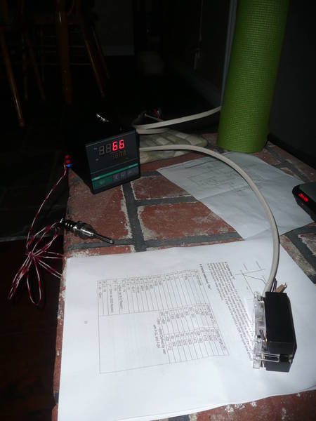
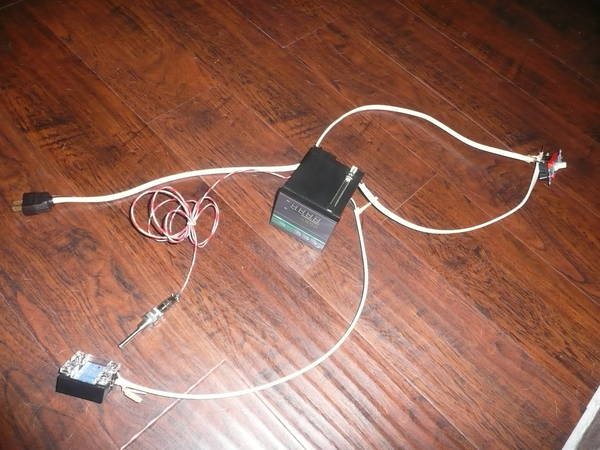
Just an FYI but the online prices at Murray Equipment are not accurate. I guess they have had troubles with their system and the prices are up. I think all the stuff cost me about $64 instead of $51 which the web said.

Edit: it was the wrong price in house, web prices are good. Saved me $15 :)
 
Anyone know what the typical amps a electric dryer would have on its circuit? I know I could check when I get home, but I am curious if I could plug in there if I make a E-Kettle. I know the dryer pulls about 5500w which is the same as an element I might get.
 
I got everything minus the SS pipe stuff today. Looks like I will need some more wires to go from and to the controller, off to the store on the way home :) Wish me luck, I will probably come back with questions.
 
so I have wired up most of it and figured most of it out but my temp is reading like 34 which is way too hot for Celcius and way too cold for F, so what the heck is that plus it is sending to the output no matter if I am above or below the set point. Anyone else run into this?

I am using the following RTD sensor

http://www.auberins.com/index.php?main_page=product_info&cPath=15&products_id=96

What Input Selection "Sn" do I use?

I also have the 1/4 DIN model http://www.auberins.com/index.php?main_page=product_info&cPath=1&products_id=102

The red probes from the rtd go onto pins 14 and 15, and the blue one on 16.
It's a pt100 rtd so use SN=21.

good luck!
 
Here are some pics from testing tonight

P1050709.JPG


hooked it up to a single pole switch

P1050712.JPG
 
Ive got a temperature controller, and probe that all runs on 24DC, what do I need to buy that will turn on the power to my heating element?
 
I use a 10 quart grant to recirculate at the end of the mash to clear. Can I stick an element (running off 120V service) in it and recirculate during the mash to hold temp?
 
I got my 1/4 DIN PID Temperature Controller with 20AMP SSR hooked up with Liquid tight RTD sensor, 2” probe, 1/4 NPT Thread probe.

Things look like their working but the element is not heating. I am only getting 23.6 volts on my meter out and in to the SSR. Why is this 23.6 and not 120? I get zip on the output of the SSR.


ahhh I just want this thing working.

Hi, please post a wiring schematic of what you have wired and how you are measuring so we all can help.
 
Hi, please post a wiring schematic of what you have wired and how you are measuring so we all can help.

I have copied this diagram with exceptions of: my output of the SSR goes directly to the element and I have a 3 prong thermocouple

RIMS%20Circuit%20Diagram.jpg


I have my pump on a separate circuit so I can turn it on and off by itself while I test.

The probe seems to be doing good, reading the right temps and giving the green output light when it is suppose to. The SSR light also lights up but sometimes blinks.

I have been going through the manual and the option for "OP-A" is for the output and is currently set to 0 which is say it should be for "Time-proportional output"
 
I have to have some sort of setting wrong, because even when I have my set temp below the actual temp it still sends out but it pulses I guess like the manual mode but I don't know much about that right now.

When the SSR lights is on, my meter picks up 23.6V being sent and when it is off, it shows 0. The output of the SSR is 0 all the time though.
 
I have copied this diagram with exceptions of: my output of the SSR goes directly to the element and I have a 3 prong thermocouple

The probe seems to be doing good, reading the right temps and giving the green output light when it is suppose to. The SSR light also lights up but sometimes blinks.

I have been going through the manual and the option for "OP-A" is for the output and is currently set to 0 which is say it should be for "Time-proportional output"

Not sure how you have yours wired... but in that drawing, the output of the SSR goes directly to the heat element. I think you have a wiring problem... When you have an LED illuminated on the SSR, you should have output regardless of the PID settings.
 
Not sure how you have yours wired... but in that drawing, the output of the SSR goes directly to the heat element. I think you have a wiring problem... When you have an LED illuminated on the SSR, you should have output regardless of the PID settings.

I thought the diagram had the negative going to the element and the positive going to the hot then the other element contact goes to the neutral?
 
the PID send a signal to the SSR which in turn will close the circuit and you have power to your elelement. Do you have the right PID for SSR or universal and not relay? If it is universal is it configured for SSR
 
the PID send a signal to the SSR which in turn will close the circuit and you have power to your elelement. Do you have the right PID for SSR or universal and not relay? If it is universal is it configured for SSR

Yes, I have the SSR model. My error was not hooking it up right from the SSR forward. I will have to wait until Sunday to find out but that is what I am hoping that is what I did wrong. But was is the 23.6V thing all about? I get 120V into the PID and 23.6V on the SSR out of the PID. This may again be because the circuit is not complete.... I hope.
 
That is correct the PID is powered off of 120v but the control signal sent out of the PID to SSR is lower than 120v probably 23.6v and the output of the SSR should be 120v when the circuit is closed
 
That is correct the PID is powered off of 120v but the control signal sent out of the PID to SSR is lower than 120v probably 23.6v and the output of the SSR should be 120v when the circuit is closed

Ok, that's what I like to hear :) I should be in good shape then. Now I need to organize this thing into a box. Anyone know where to get a good deal on a junction or electrical box? It was like $23 for a 8x8x4 at lowes :confused:


OH yeah and I need a stand to mount this on, minor detail ;)
 
I thought the diagram had the negative going to the element and the positive going to the hot then the other element contact goes to the neutral?

The + and - on the SSR represent the "control" voltage from the PID which is DC.
The 115 VAC Nue, is the Neutral AC supply and connects to the Element AND the PID.

The 115 VAC Hot, is the HOT AC supply and connects to the SSR AND PID.

The other connection between the element and the SSR provides the 120 VAC Hot to the element only when the PID sends a DC Control signal to the SSR.

Thanks, I got it now I guess i just didn't know what the purpose of the SSR was, I was thinking it worked a different way, just sending the power directly through and the wiring in the diagram was because a pump was also in. Now I know.

Almost I have one more dumb question. Just to comfirm, the Output 7 and 8 on the PID go to the Input of the SSR correct? Just a tad confusing because you have hot power coming into the output from the other side if that is the case.
 
Just a tad confusing because you have hot power coming into the output from the other side if that is the case.

the SSR acts like a switch inline with the hot side of 120vac. With one side live pointing to the receptacle and the other side dead pointing to the element. Now flip the switch to on (PID function) and the path is closed.

Almost I have one more dumb question. Just to comfirm, the Output 7 and 8 on the PID go to the Input of the SSR correct?

if you have Right SYL-4352 then yes 7 is + and 8 is -
 
1 x 1/4 DIN PID Temperature Controller * Output Configuration: Relay Contactor $59.50

Is this what you ordered and this is from Auberins

The output configuration can not be changed by user. It has to be set at factory. Please select the correct output configuration at the bottom of this page.

Should you have gotten the SSR control output
 
Is this what you ordered and this is from Auberins

The output configuration can not be changed by user. It has to be set at factory. Please select the correct output configuration at the bottom of this page.

Should you have gotten the SSR control output

Yeah, I screwed up when ordering, the guy emailed me right after ordering to check if I meant to order it with the SSR output. I agreed with him :)

Thanks for checking though!
 

Latest posts

Back
Top