• Please visit and share your knowledge at our sister communities:
  • If you have not, please join our official Homebrewing Facebook Group!

    Homebrewing Facebook Group

Replacement firmware for iSpindel (GravityMon)

Homebrew Talk

Help Support Homebrew Talk:

This site may earn a commission from merchant affiliate links, including eBay, Amazon, and others.
Sorry, but I accidentally switched my spindel and the test version is now in my CCT so I cannot perform any more tests in the coming weeks.
 
1st "live" test of v2 in a small batch of Belgian Dubbel.
P1010760.JPG

One spindel with v2.0.0a4 and one with v1.3.0b3.
Let's see how v2 behaves the coming 2 weeks. MQTT push test was working fine in the latest alpha. Great work!
 
Wondering if you'd consider supporting the ESP32-C6 variant, considering the improvements over the older C3?
I dont think it comes in a mini form factor like the c3/s2/s3 (or I have not seen it). I prefer the s3 mini which works much better.

Its not a problem to support more cpu's but it also needs to fit existing pcb and have the same formfactor as d1 mini.
 
Last edited:
Does anyone use the BLE feature on Gravitymon with a ESP32C3 or ESP32S3? I have been working on a feature for tiltbridge that can handle the new data formats and relay those to a server using HTTP. Currently its a standalone software but the intention is to integrate it into tiltbridge once I have tested it for stability. It will run on an ESP32 PRO or ESP32S3 PRO (some formats require an BLE5 chip)
 
I dont think it comes in a mini form factor like the c3/s2/s3 (or I have not seen it). I prefer the s3 mini which works much better.

Its not a problem to support more cpu's but it also needs to fit existing pcb and have the same formfactor as d1 mini.
https://www.dfrobot.com/product-2778.html -- a "micro" version. But, I don't see why it needs to fit the existing PCB, and the firmware should be able to just be applied to any esp32-c3/s2/s3 and adjusted PCB for different container sizes. In any event, here's another one in the "mini" space -- https://www.amazon.com/SparkFun-Qwiic-Pocket-Development-Board/dp/B0CL6GGT7Q
 
Does anyone use the BLE feature on Gravitymon with a ESP32C3 or ESP32S3? I have been working on a feature for tiltbridge that can handle the new data formats and relay those to a server using HTTP. Currently its a standalone software but the intention is to integrate it into tiltbridge once I have tested it for stability. It will run on an ESP32 PRO or ESP32S3 PRO (some formats require an BLE5 chip)
I'd be interested! I was able to get TiltBridge to read a C3 iSpindel in Fermentrack, but never tested it out during a fermentation.
 
https://www.dfrobot.com/product-2778.html -- a "micro" version. But, I don't see why it needs to fit the existing PCB, and the firmware should be able to just be applied to any esp32-c3/s2/s3 and adjusted PCB for different container sizes. In any event, here's another one in the "mini" space -- https://www.amazon.com/SparkFun-Qwiic-Pocket-Development-Board/dp/B0CL6GGT7Q
The idea behind this project is to use existing hardware with modifications. Since there are a lot of available pcb options for building an ispindel with the MINI formfactor then it's quite easy for someone to build an version with newer hardware.

But if someone creates a pcb for the mini versions or there is some kind of adapter that would make it possible to use those mini boards then i dont see why gravitymon could not support those. For now i stick with the mini formfactor due to these reasons. I'm not a hardware design person so I leave that to others unless i really need to.
 
I'd be interested! I was able to get TiltBridge to read a C3 iSpindel in Fermentrack, but never tested it out during a fermentation.
Perfect, I will make the project public and publish a build. I guess you are using the ESP32 PRO which will work with the extended and service options but not EddyStone since that requires BLE 5. I found that an ESP32S3 PRO can be used which I'm currently testing myself.

I have added support for the TFT that Thorrak recommends but no other options for now. It should run without a display as well.
 
I'd be interested! I was able to get TiltBridge to read a C3 iSpindel in Fermentrack, but never tested it out during a fermentation.
Here is the link to the project; https://github.com/mp-se/gravitymon-blegw, i've also added it to brewflasher (Gravitymon Gateway). Default wifi password is same as for gravitymon and the UI is more or less a subset of that project so most of that documentation should apply to this project as well
 
https://www.dfrobot.com/product-2778.html -- a "micro" version. But, I don't see why it needs to fit the existing PCB, and the firmware should be able to just be applied to any esp32-c3/s2/s3 and adjusted PCB for different container sizes. In any event, here's another one in the "mini" space -- https://www.amazon.com/SparkFun-Qwiic-Pocket-Development-Board/dp/B0CL6GGT7Q
Also, apparently new on the market according to an email off PiHut, an ESP32-C6 Mini Development Board.
https://thepihut.com/products/esp32-c6-mini-development-board?mc_cid=a9abdf7f5f
 
I am busy building a couple of Ispindels one with a esp32 c3 super mini (waiting on pcbs) in a prototype at the moment, the other in an esp8266 d1 mini on a v3.2 cherry Phillips board which I managed to whittle down to fit in a rapt pill container, as they are tight to open and close I have also fitted them with a wireless charger and magnetic reset (based on the drv5032 ultra low current hall switch) both working well, I will upload all the details when I am complete with the build (not done the balancing or calibrating yet).
I am stuck on the setting up for it to read on the ispindhub or the brewpiless, not sure where I am going wrong but the ispindhub refuses to read it (probably my bad understanding of the setup as it looks different on the gravitymon software. has anyone done this? and can you help me?
I also have a spare build on esp8266 d1 mini that I will test out with the V2.0 software.
2 photos one showing the magnetic charger working and the unit as a whole, the other the magnetic reset unit.
 

Attachments

  • IMG_20240715_163753.jpg
    IMG_20240715_163753.jpg
    2.6 MB
  • IMG_20240715_163849.jpg
    IMG_20240715_163849.jpg
    1.3 MB
I am busy building a couple of Ispindels one with a esp32 c3 super mini (waiting on pcbs) in a prototype at the moment, the other in an esp8266 d1 mini on a v3.2 cherry Phillips board which I managed to whittle down to fit in a rapt pill container, as they are tight to open and close I have also fitted them with a wireless charger and magnetic reset (based on the drv5032 ultra low current hall switch) both working well, I will upload all the details when I am complete with the build (not done the balancing or calibrating yet).
I am stuck on the setting up for it to read on the ispindhub or the brewpiless, not sure where I am going wrong but the ispindhub refuses to read it (probably my bad understanding of the setup as it looks different on the gravitymon software. has anyone done this? and can you help me?
I also have a spare build on esp8266 d1 mini that I will test out with the V2.0 software.
2 photos one showing the magnetic charger working and the unit as a whole, the other the magnetic reset unit.
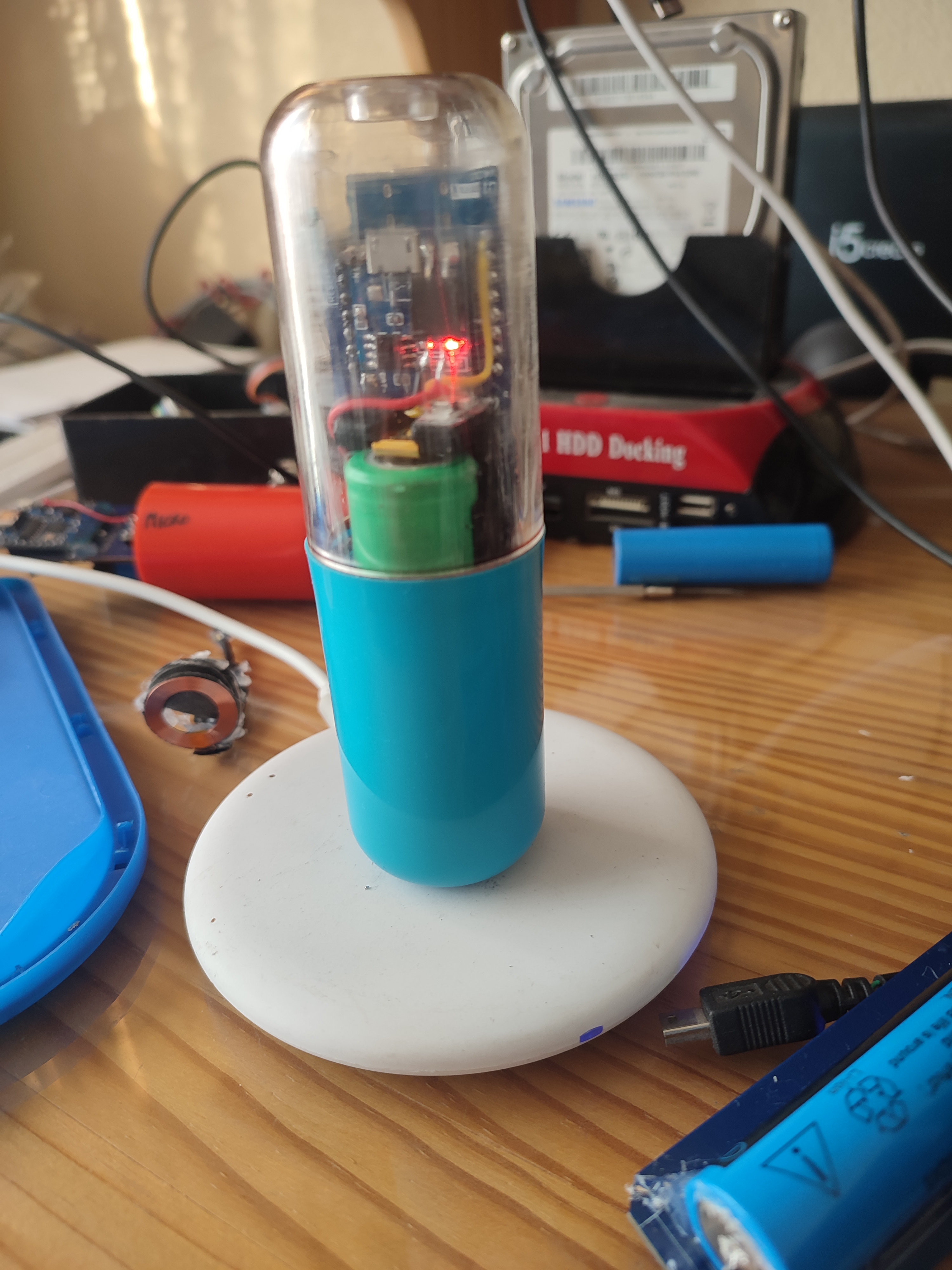
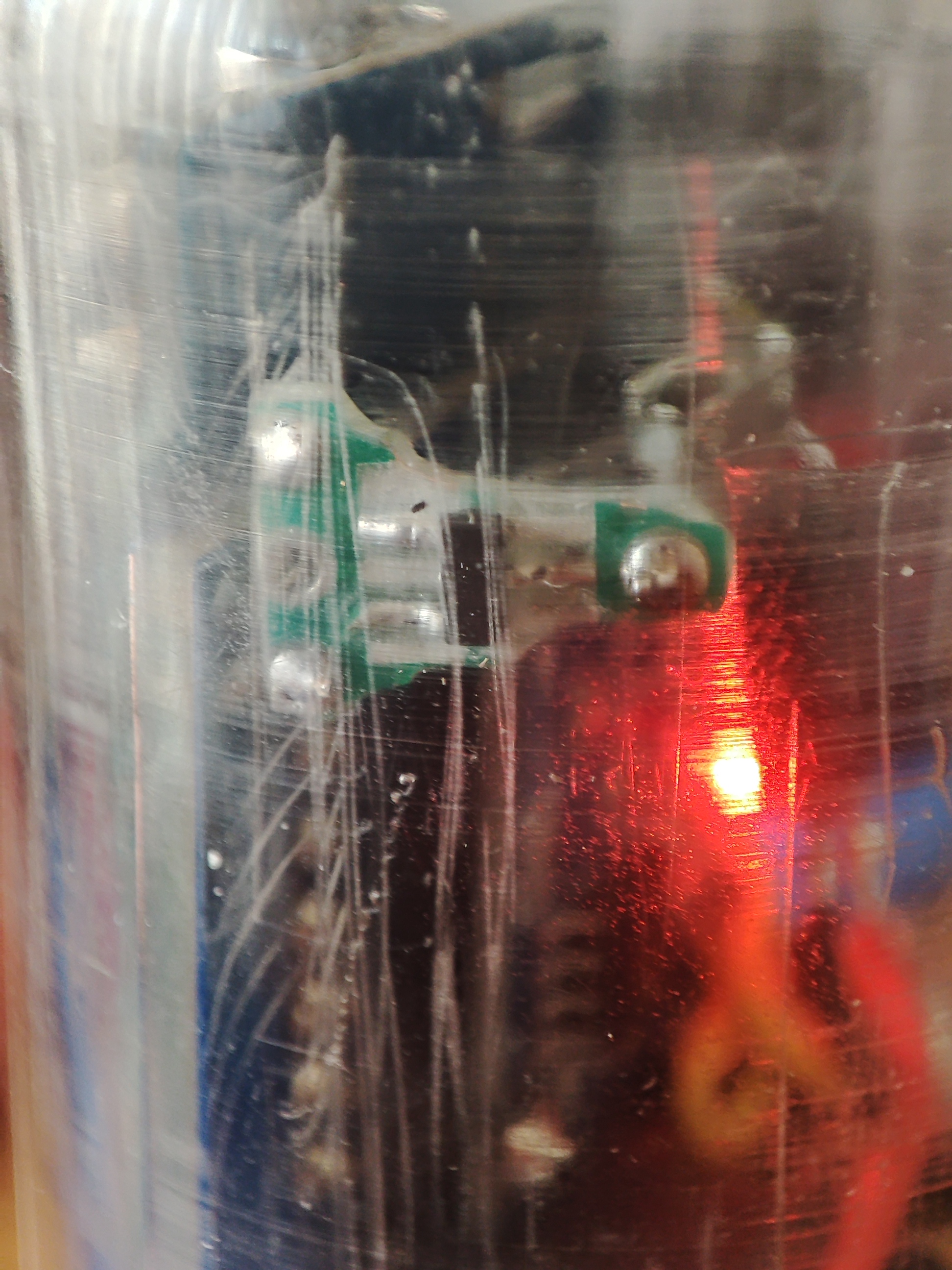
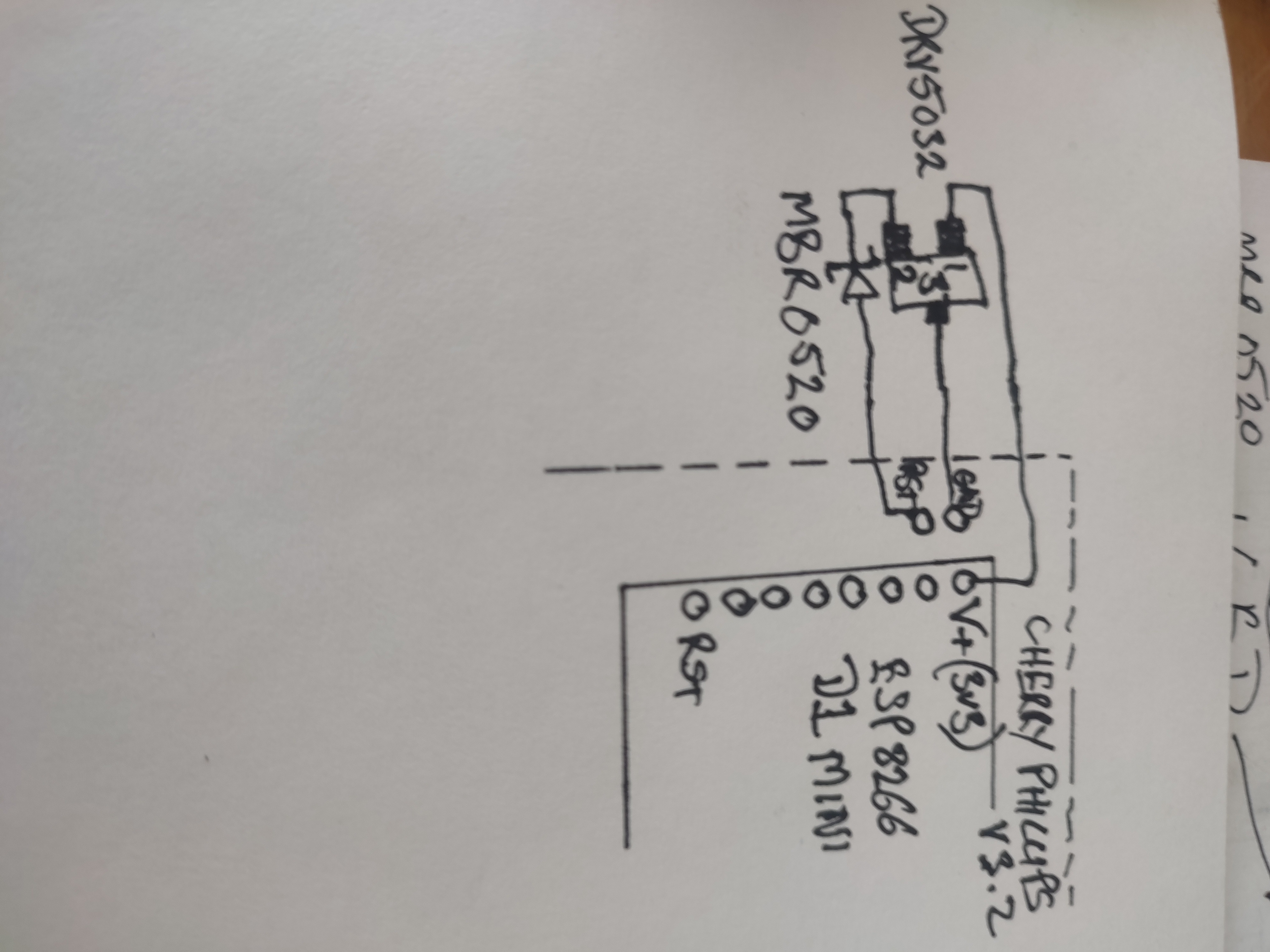
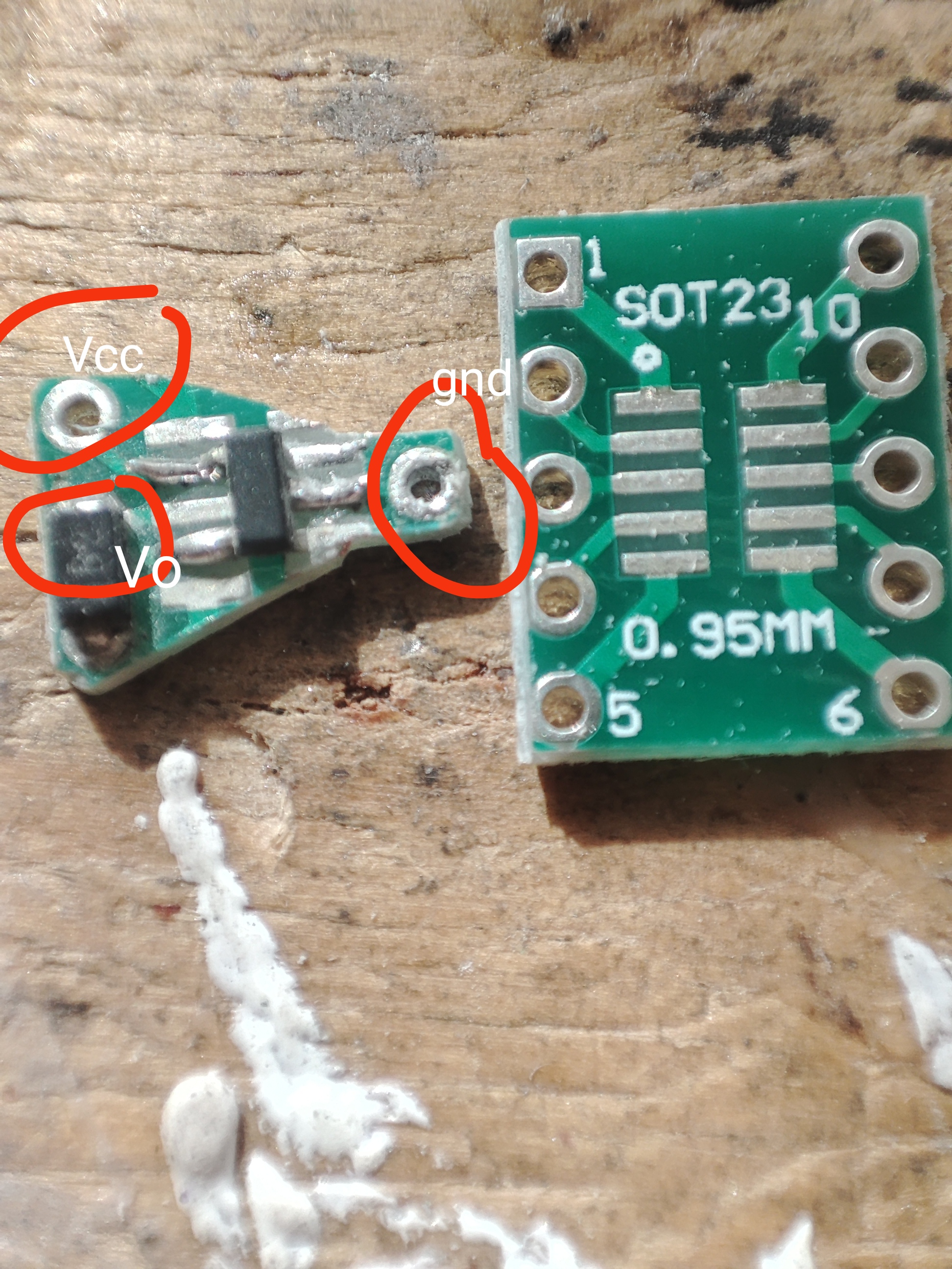
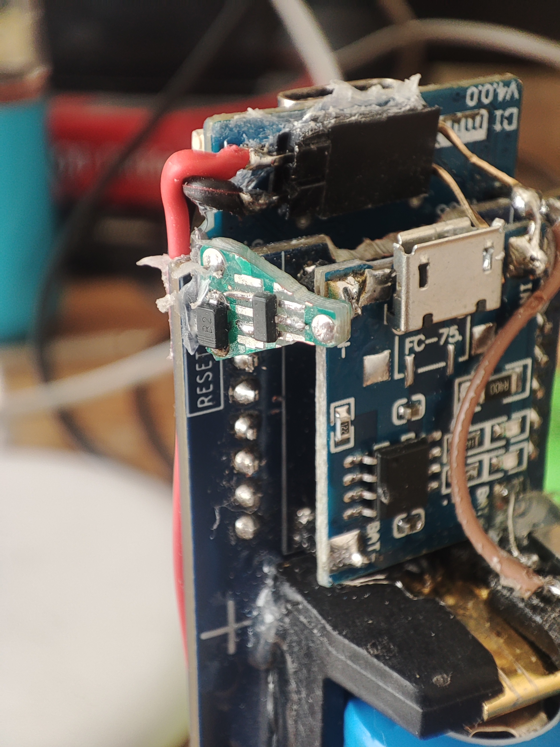
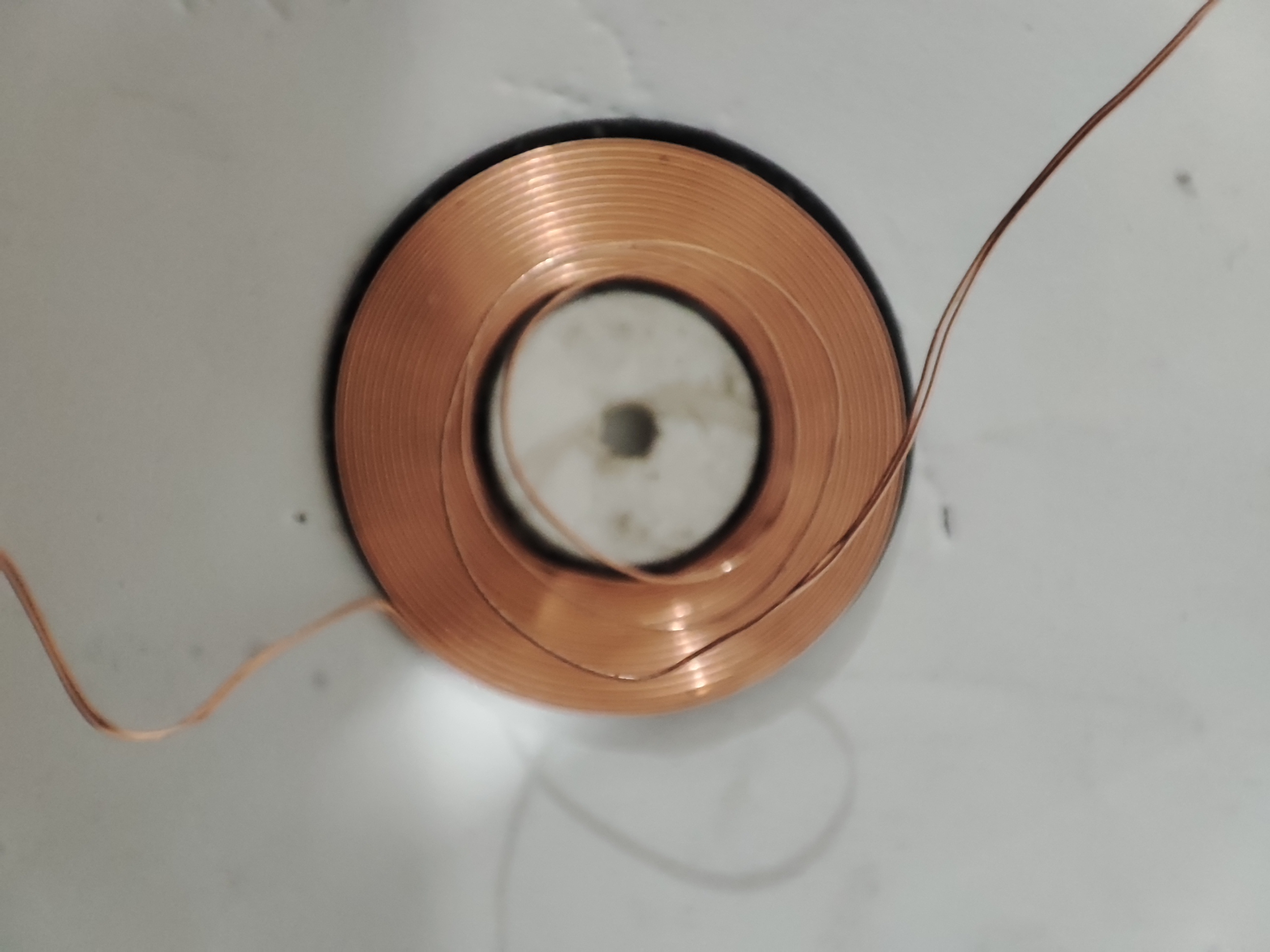
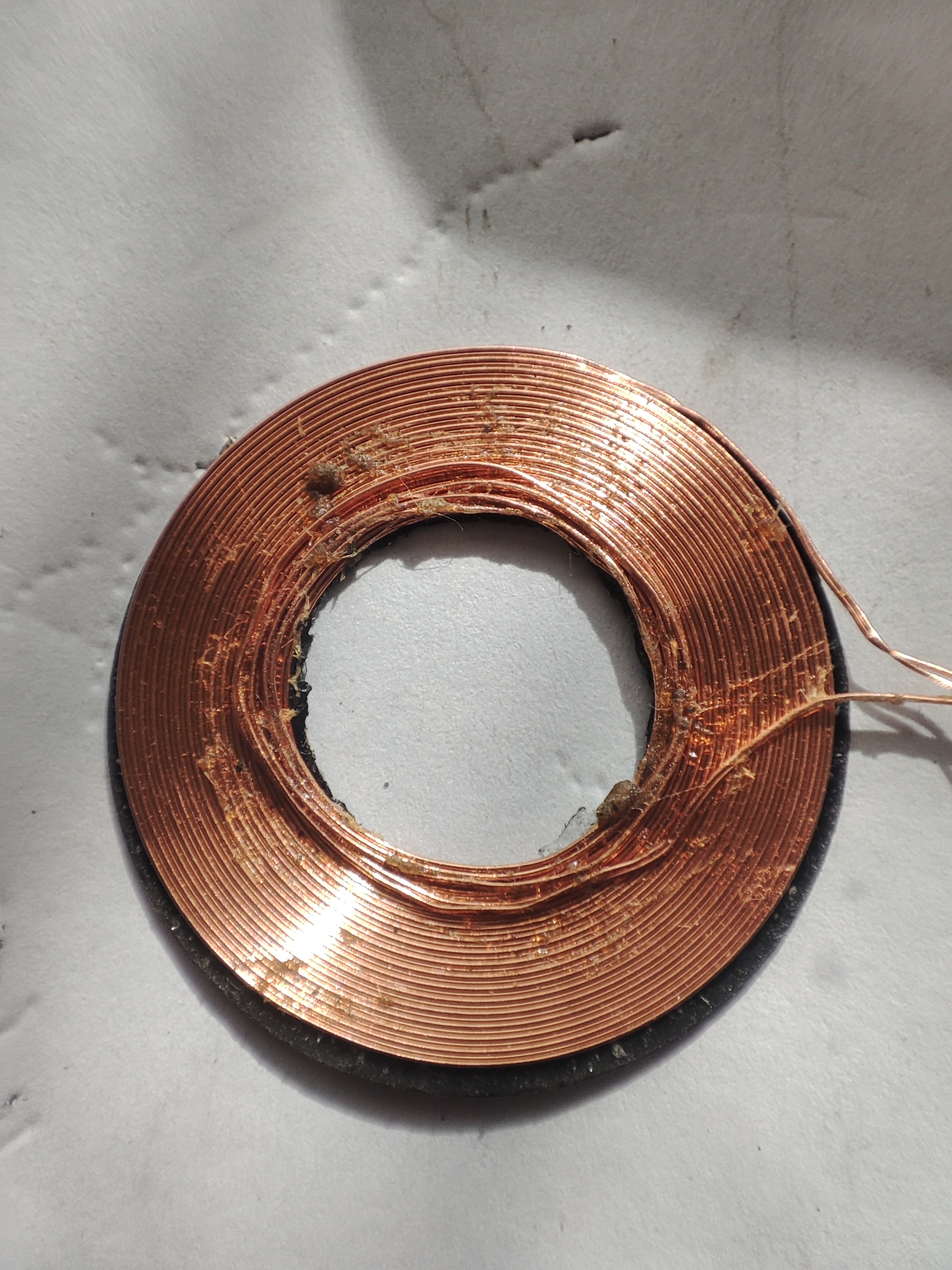
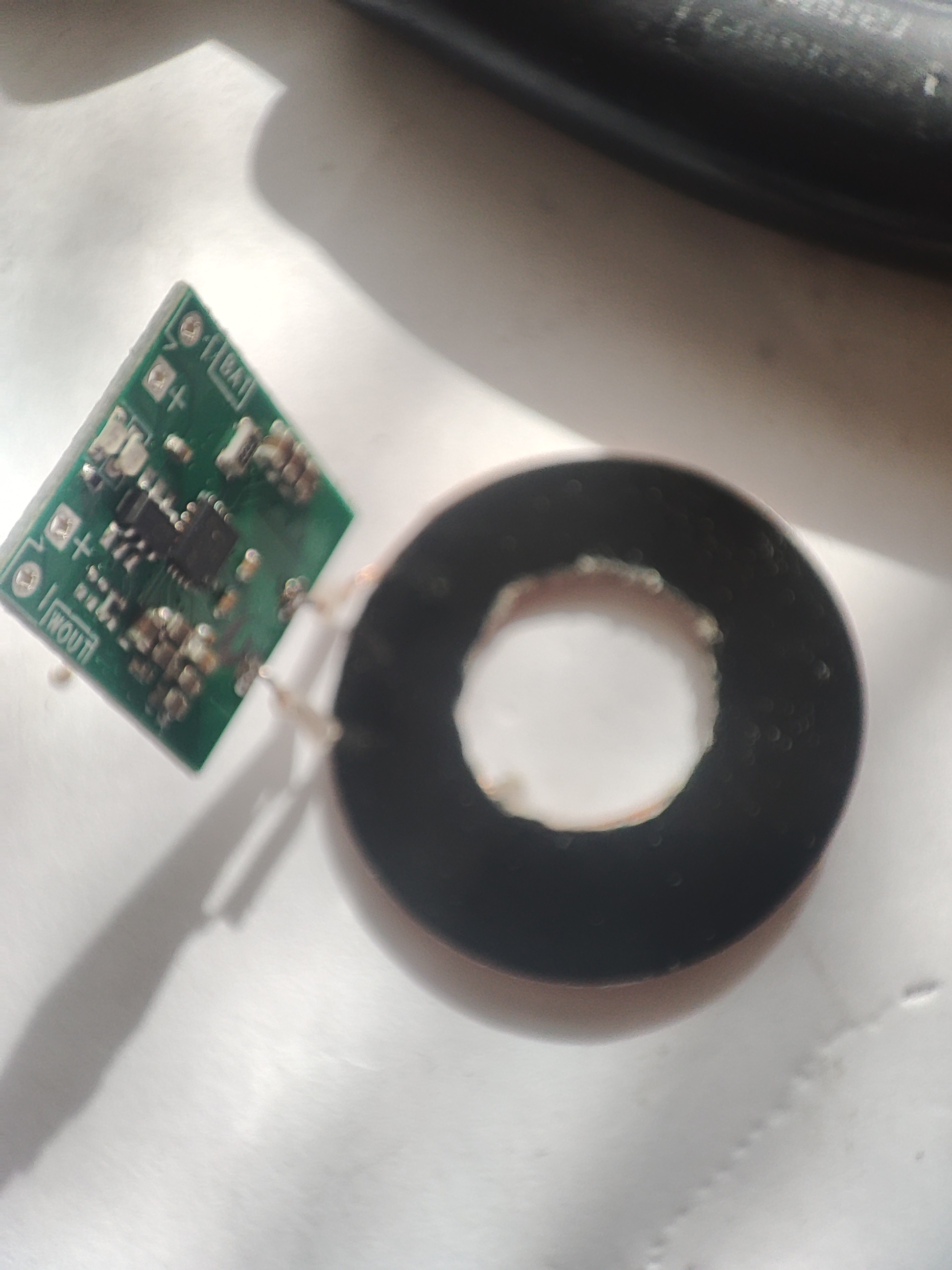
Really nice, looking forward to the documentation.

I have not tested ispindhub so I dont know what it expects. In the default settings I have extended the json payload so you could try to change the format to standard ispindel and see if that works. You could also try to get the serial output from the device to see if that gives any clues to what the error is.

I'm currently working on my own gateway for gravitymon and in the new version I will also support wifi connection (i started that to handle the new ble formats) but I have some reception problems in my brewery so I wanted to see if a gateway could help with that. It looks like the esp connected to the last ap and not the closest one... Give me a shout if you want to try that out. I currently have builds for the tiltbride hardware (ESP32 PRO and ESP32s3 PRO with TFT screen) but can easily compile a version for any other board.
 
hi @mper a build for the esp32 c3 would be of great help for me as I build my unit for this device.
is the setup for the ispindel in the push settings? what format do I need for it? I have lots of experience in board and circuit design but networking is not a strong point for me.
 
hi @mper a build for the esp32 c3 would be of great help for me as I build my unit for this device.
is the setup for the ispindel in the push settings? what format do I need for it? I have lots of experience in board and circuit design but networking is not a strong point for me.
It depends on which version you use. In the 1.x its under the format settings but in 2.x i have placed all the settings under the push target for better overview. it should be called iSpindle under the pre-defined format templates.
 
2.0 beta 1 is now live on github, still some testing and documentation to do but the esp8266 has one successful brew behind it. Both projects are live in brewflasher as well.

https://github.com/mp-se/gravitymon/releases/tag/v2.0.0-beta1

The companion gateway now as WIFI support for the wifi direct feature in the new beta. It runs on an ESP32 PRO or ESP32s3 PRO with Lolin TFT (same hardware as the tiltbridge), there is also an build for an ESP32c3 without TFT for testing. The gateway does not have tons of features since it was initially a test for the new ble formats but that might change based on your feedback.

https://github.com/mp-se/gravitymon-gateway/releases/tag/0.3.0-beta1
 
here is my build for the magnetic reset, I used a drv5032FA which is push pull, a drv5032FC is open drain and more suitable if available but this worked for me with a schottky diode in series with the output to prevent loading the device with reset and wake-up. I mounted the device on a sop 10pin to dip adaptor board for strength and stability then trimmed it to size.
 

Attachments

  • IMG_20240716_141520.jpg
    IMG_20240716_141520.jpg
    2.6 MB
  • IMG_20240716_133430.jpg
    IMG_20240716_133430.jpg
    1.6 MB
  • IMG_20240716_133430.jpg
    IMG_20240716_133430.jpg
    1.6 MB
  • IMG_20240718_100633.jpg
    IMG_20240718_100633.jpg
    1.3 MB
  • IMG_20240716_141520.jpg
    IMG_20240716_141520.jpg
    2.6 MB
here are the aliexpress links to the components I used.

hall effect switch

(5PCS)DRV5032FADBZR DRV DRV5032 DRV5032FA DRV5032FADB DRV5032FADBZ 100% Brand New Original IC SOT23-3

https://a.aliexpress.com/_EJuDtqr


schottky diode

100PCS MBR0520T1G MBR0530T1G MBR0540T1G SOD-123 MBR0520 MBR0530 MBR0540 SMD Schottky diode

https://a.aliexpress.com/_EIVSdGx


adaptor board dip to 10 pin sot23

10PCS Adapter PCB Circuit Board Kit SMD QFP LQFP QFN FQFP Turn To DIP SOP MSOP SSOP TSSOP SOT23 8 10 14 16 20 24 28 SMT To DIP

https://a.aliexpress.com/_EQDw4CB
 
this is my magnetic charging device, I considered it essential addition for the use of a rapt pill housing as they are difficult to open and close, wether it is useful or adaptable to a ispindel tube I don't know as I haven't got one to test. the rapt pill does have a magnetic charging unit of the shelf but it it's a little pricy compared to my design. some effort is required to make and fit it though.
first the coil should be detached from the pc board which comes with it, mark the pad which connects to the center of the coil. the coil center is too small to fit over the raised section at the bottom of the rapt pill tube so 4 turns need pulling carefully out of the center of the coil, first fit the sticky pad which comes with it to the side without the return wire, the turns are then pulled out and need winding back over the existing coil I get 3 turns back on the coil which suffices, they need winding back on flat and holding down with contact adhesive one turn at a time and then back to outside of the coil. I then cover the coil with super glue and sprinkle bicarbonate of soda over the glue, this gives it strength and rigidity without interfering with the coils performance. once done the center needs cutting out of the coil backing pad. I then take 2 round 3M double sided sticky pads to build it up then carefully stick it to the battery box so it aligns with the raised rum at the bottom of the pill tube, it needs to be able to rotate freely. the rapt pill kegland site had a good tutorial on the procedure for attaching.
the board can now be reattached same as it was previously, heat shrink covering is a good addition to the board, the board I purchased has two outputs on at 4.2V to charge the battery directly which would allow the omission of the tp4056, I chose to use the other output of 5V and not influence the balance any more than necessary. this should then be connected to the input of the tp4056 either directly or via a 2 pin header male female combination.
 

Attachments

  • IMG_20240716_174321.jpg
    IMG_20240716_174321.jpg
    950.2 KB
  • IMG_20240716_175931.jpg
    IMG_20240716_175931.jpg
    822.3 KB
  • IMG_20240717_101302.jpg
    IMG_20240717_101302.jpg
    1.6 MB
  • IMG_20240717_101754.jpg
    IMG_20240717_101754.jpg
    3.4 MB
  • IMG_20240717_101819.jpg
    IMG_20240717_101819.jpg
    1.7 MB
  • IMG_20240717_102838.jpg
    IMG_20240717_102838.jpg
    982.5 KB
  • IMG_20240717_120458.jpg
    IMG_20240717_120458.jpg
    1.9 MB
the link to the coil purchased on aliexpress, there are a few similar ones with either 4.2V or 5V single outputs available but as yet this is the only one I have used.

charging receiver coil dual output

[lithium battery wireless charging] 5W wireless charging receiver module small coil built-in 3.7V modification scheme

https://a.aliexpress.com/_EH4mvCb
 
this is my magnetic charging device, I considered it essential addition for the use of a rapt pill housing as they are difficult to open and close, wether it is useful or adaptable to a ispindel tube I don't know as I haven't got one to test. the rapt pill does have a magnetic charging unit of the shelf but it it's a little pricy compared to my design. some effort is required to make and fit it though.
first the coil should be detached from the pc board which comes with it, mark the pad which connects to the center of the coil. the coil center is too small to fit over the raised section at the bottom of the rapt pill tube so 4 turns need pulling carefully out of the center of the coil, first fit the sticky pad which comes with it to the side without the return wire, the turns are then pulled out and need winding back over the existing coil I get 3 turns back on the coil which suffices, they need winding back on flat and holding down with contact adhesive one turn at a time and then back to outside of the coil. I then cover the coil with super glue and sprinkle bicarbonate of soda over the glue, this gives it strength and rigidity without interfering with the coils performance. once done the center needs cutting out of the coil backing pad. I then take 2 round 3M double sided sticky pads to build it up then carefully stick it to the battery box so it aligns with the raised rum at the bottom of the pill tube, it needs to be able to rotate freely. the rapt pill kegland site had a good tutorial on the procedure for attaching.
the board can now be reattached same as it was previously, heat shrink covering is a good addition to the board, the board I purchased has two outputs on at 4.2V to charge the battery directly which would allow the omission of the tp4056, I chose to use the other output of 5V and not influence the balance any more than necessary. this should then be connected to the input of the tp4056 either directly or via a 2 pin header male female combination.
 

Attachments

  • IMG_20240716_174321.jpg
    IMG_20240716_174321.jpg
    950.2 KB
  • IMG_20240716_175931.jpg
    IMG_20240716_175931.jpg
    822.3 KB
  • IMG_20240717_101302.jpg
    IMG_20240717_101302.jpg
    1.6 MB
  • IMG_20240717_101754.jpg
    IMG_20240717_101754.jpg
    3.4 MB
  • IMG_20240717_101819.jpg
    IMG_20240717_101819.jpg
    1.7 MB
  • IMG_20240717_102838.jpg
    IMG_20240717_102838.jpg
    982.5 KB
  • IMG_20240717_103355.jpg
    IMG_20240717_103355.jpg
    3 MB
  • IMG_20240717_120458.jpg
    IMG_20240717_120458.jpg
    1.9 MB
I have managed to fit an ispindel inside a rapt pill housing, In south Africa the ispindel housing is difficult to get whilst the rapt pill is easy, I purchased 5 cherry Phillips v3.2 boards and reshaped them, just got enough off either side to fit them in the housing without damaging any tracks although it is a fairly tight fit with the battery in a housing.
I also made the two additions to the build and used the gravitymon software. first mod was to fit wireless charging as it it's problematic to open and close the container due to the o rings although these are good and make the unit a good pressure tight device they are difficult to open and close even when lubricated. the other mod is a magnetic reset to avoid having to Open for calibration and maintenance.
one side of the pcb had more removed than the other owing to the presence of tracks.

Attachments​

  • IMG_20240717_124305.jpg
    IMG_20240717_124305.jpg
    37.1 KB · Views: 0
  • IMG_20240717_120458.jpg
    IMG_20240717_120458.jpg
    23.7 KB · Views: 0
  • IMG_20240419_084924.jpg
    IMG_20240419_084924.jpg
    59.8 KB · Views: 0
  • IMG_20240419_084954.jpg
    IMG_20240419_084954.jpg
    60.1 KB · Views: 0
  • IMG_20240419_085108.jpg
    IMG_20240419_085108.jpg
    54.8 KB · Views: 0
  • IMG_20240419_085132.jpg
    IMG_20240419_085132.jpg
    46 KB · Views: 0
 
1st "live" test of v2 in a small batch of Belgian Dubbel.
View attachment 851438
One spindel with v2.0.0a4 and one with v1.3.0b3.
Let's see how v2 behaves the coming 2 weeks. MQTT push test was working fine in the latest alpha. Great work!
v2 behaved similar to v1.3 during two weeks of fermentation. I had no issues with it at all running on the s2 mini
 
Wouldn't a reed switch always closed instead of the normal power switch work? lot less complicated than the magnetic switch, Then just a magnet in the base will turn off the device.

However I thought the gravity mon software was configured to put the ispindel into off mode when inverted vertically?
There is a feature in gravitymon that will go into indefinite sleep when placed on the cap. You will need to force a reset to get out of that mode.

I have tested using an open reed switch and magnet to do that.
 
Wouldn't a reed switch always closed instead of the normal power switch work? lot less complicated than the magnetic switch, Then just a magnet in the base will turn off the device.

However I thought the gravity mon software was configured to put the ispindel into off mode when inverted vertically?
if this in response to my magnetic reset, it it's not a power on off switch but a way to reset the device and force it into configuration mode when it goes to sleep, a bit lighter than a glass reed switch but definitely a bit more complicated. just another option for anyone interested.
 
Great news, any things that you see could be improved ?
Not much really.
I'm a little bit unsure about the Home --> "Force Gravity Mode" button behavior:
If I tick it to disable sleep mode, enter another menu and return to Home, it is unticked.
Have not checked if there's a connection with the battery voltage is higher than 4.15V (= always config mode)
 
Not much really.
I'm a little bit unsure about the Home --> "Force Gravity Mode" button behavior:
If I tick it to disable sleep mode, enter another menu and return to Home, it is unticked.
Have not checked if there's a connection with the battery voltage is higher than 4.15V (= always config mode)
I will check that, it should remain ticked even if you move between menus.
 
hi @mperi have designed a pcb to take the ESP32C3 super mini form factor module (I am busy making it a shared project on pcbway), there are 2 problems, 1) I still need to get the blue led working looks like I may have to create a separate environment for this as the normal C3 has a multi colour led and doesn't look to be compatible in this regards, 2) I can get the board up and running on the 1.4 version but when I try to load the 2.0 version I get an I2Cread error 263 and it will not run, do you have any ideas what the issue may be.
 
hi @mperi have designed a pcb to take the ESP32C3 super mini form factor module (I am busy making it a shared project on pcbway), there are 2 problems, 1) I still need to get the blue led working looks like I may have to create a separate environment for this as the normal C3 has a multi colour led and doesn't look to be compatible in this regards, 2) I can get the board up and running on the 1.4 version but when I try to load the 2.0 version I get an I2Cread error 263 and it will not run, do you have any ideas what the issue may be.
That error have been there for a while and i finally found the issue an hour ago. The led pin on the esp32c3 is the same as the data for the gyro so this is the root cause. The fix is to disable (not use) the led on that board so if the pins are the same as for your board the new build in the dev branch should work
 
hi @mper does this mean that jtag is automatically enabled on the current version? I have been using gpio6 and 7 for my i2c comms as pin 8 is the blue led which I would like to work as it gives me an indication of the state of the system.
I am still not sure where to find the pin definition for the LED, maybe you could point me in the right direction.
JTAG is a hardware setup not software, the LED is defined as PIN_LED which is the same pin used for the Gyro in the ispindle design. This is defined in the header for your board.
 
Back
Top