New brewstand - Gas Valve and Inbird wiring

Homebrew Talk - Beer, Wine, Mead, & Cider Brewing Discussion Forum

Help Support Homebrew Talk - Beer, Wine, Mead, & Cider Brewing Discussion Forum:

This site may earn a commission from merchant affiliate links, including eBay, Amazon, and others.

eryk4381

Well-Known Member
Joined
Jan 6, 2012
Messages
145
Reaction score
0
Location
Wilsonville
OK guys I am stuck. I have a total build almost setup and will be posting a full write up once I am finished but I need assistance. I have:
1 Inkbird Timer
2 Inbird ITC-106 Temp controllers
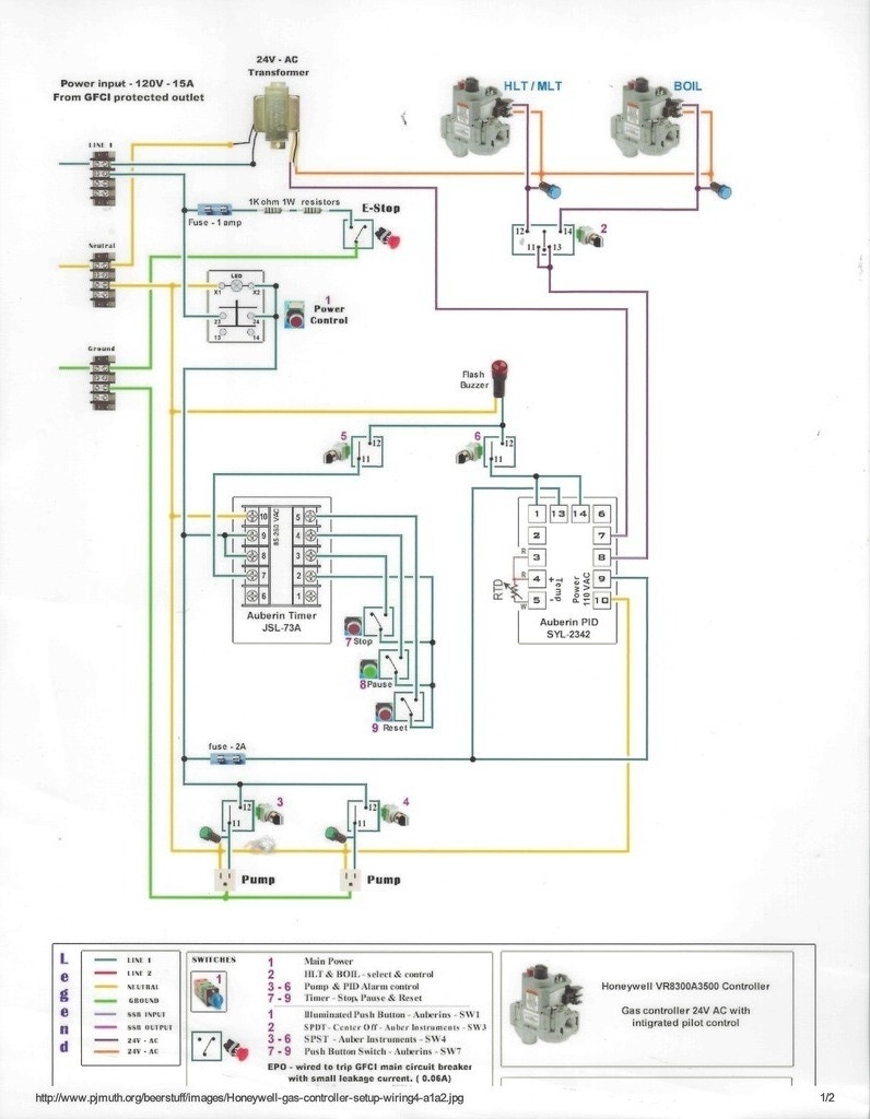
2 Honeywell VR8200 gas valves

I am trying to connect this altogether to time both the MLT and HLT. I have it all wired up for power and I get were the 120 goes into the controllers and the temp probes but the part where it goes it all goes OUT to the SSR's and the 24v Transformer I have to the gas valves. I fluent in electronics but not gas and I just cant for the life of me figure this out.

How do the controller's power the transformer to then power the gas valves?
Where do the SSR's come in since I'm reading 12V coming out of the temp controllers OUT NO side at only 12V?
 
If you bought the ITC-106VH the controllers run on 120vac, and produce 12VDC outputs to control your two external SSRs.


- So, starting off, you need to wire the two controllers to 120vac line/neutral plus a green safety ground.

- You'll need to wire the SSR control from each controller to its related SSR + input

- the SSR - inputs need to be wired back to the controller's DC GND; that closes the SSR control loops.

- The 24VAC transformer should have its primary side wired to the same 120VAC line/neutral pair that is wired to the two controllers.

- One of the 24VAC transformer outputs will connect to one side of the two SSRs.

- The other side of each SSR goes to the power input of its related gas valve.

- The other transformer output will connect to the 24VAC RETURN connection of both gas valves; this completes each of the 24VAC control loops (24vac transformer output through SSR switches through gas valves to 24vac transformer return).

Hopefully I didn't leave anything out...

Cheers!


Thank you!!! Sorry I have been out for awhile... But I am going to try this. Do I need to be specific on which terminals to attach to on the gas valves? TF an TH? Like I said I know a lot about electrical and very little about gas and would prefer not to blown myself up :ban:

Also, do I really NEED to put the SSR's in place or can I leave them out? Wont the temp controller shut the valves on and off by themselves?

Thanks again!
 
Thank you!!! Sorry I have been out for awhile... But I am going to try this. Do I need to be specific on which terminals to attach to on the gas valves? TF an TH?[...]

iirc the two gas controller connections are TH and TR, and yes, it's important to get them right: your SSR-switched 24 VAC should connect to TH while TR returns to the other side of the 24 VAC secondary winding.

Also, do I really NEED to put the SSR's in place or can I leave them out? Wont the temp controller shut the valves on and off by themselves?

If you purchased the ITC-106VH it has no internal mechanism to switch the 24 VAC needed to manage the gas controllers.
It was designed to work with an external switch - in this case an SSR with 12VDC controls...

Cheers!
 
iirc the two gas controller connections are TH and TR, and yes, it's important to get them right: your SSR-switched 24 VAC should connect to TH while TR returns to the other side of the 24 VAC secondary winding.


If you purchased the ITC-106VH it has no internal mechanism to switch the 24 VAC needed to manage the gas controllers.
It was designed to work with an external switch - in this case an SSR with 12VDC controls...

Cheers!

Please excuse my remedial drawing but I was thinking this through now that I am making time to finish this build.
From what you described this is what I came up with. Does this looks correct?

20170717_201106.jpg
 
I don't seem to be getting voltage after the inkbirds show they are "Out" of temp range. Is my wiring incorrect?
 
Wiring looks kosher now.
What does '"Out" of temp range' mean?

Cheers!

When the temp control is supposed to activate the SSR and the Gas valve. Needing to turn them on to stay in whatever desired range I have set.
UPDATE: turns out I crossed the input wires from both my temp controllers. Now I see the SSR activate with the red light but the output AC voltage from the SSRS are only about 1.5 V AC?!
The Gas valves I am pretty sure need 24v to activate.

How is this possible.
 
That could happen if the transformer is under-rated for the load.
You need to know the draw by the controllers (which obviously include solenoid valves and those chew up some watts) and make sure the current rating for the transformer exceeds that by a comfortable margin...

Cheers!
 
That could happen if the transformer is under-rated for the load.
You need to know the draw by the controllers (which obviously include solenoid valves and those chew up some watts) and make sure the current rating for the transformer exceeds that by a comfortable margin...

Cheers!

Since the SSRs may take draw which makes sense, and the controller does switching can I wire this without using the SSRs?
 
You never did specify exactly which model Inkbird you have.
Again, if you purchased the ITC-106VH it has no internal mechanism to switch the 24 VAC needed to manage the gas controllers.
It was designed to work with an external switch - in this case an SSR with 12VDC controls..
 
What is the reasoning for using SSRs OP? I would guess that a large majority of gas valve control designs I have seen did not use them. I know I didn't. I believe you could simplify your design by using one of the Inkbird (or Mypin or Auber) pids with relay output.
 
You never did specify exactly which model Inkbird you have.
Again, if you purchased the ITC-106VH it has no internal mechanism to switch the 24 VAC needed to manage the gas controllers.
It was designed to work with an external switch - in this case an SSR with 12VDC controls..
I do have the Inkbird ITC-106VH PID. On pins 6 and 8 I do get 12 v DC that switches on and off due to the PID settings but the trouble is then converting that to 26V AC for the gas valves.

If there's another PID that will do the same stuff AND give me a relay output of 26 V for the gas valves I'm all for it at this point guys. I hope I am explaining all this well enough to show how frustrating it is for these specific pieces of hardware.

The transformer is what provides the voltage for the gas valves. Below is one of P-J's old drawings that I used as a guide for what I built. I used a different Auber PID and only included one Honeywell valve for my HLT but otherwise the design is similar to mine. Maybe it will help.
XEb2ZCv.jpg
 
I do have the Inkbird ITC-106VH PID. On pins 6 and 8 I do get 12 v DC that switches on and off due to the PID settings but the trouble is then converting that to 26V AC for the gas valves.

Ok, at least the model is finally confirmed.
You indicated the LED on the SSR will now light up when the PID is calling for heat.
You should verify that in fact there is 12VDC across the SSR control inputs.
If that control is significantly below 12 volts it could cause the SSR to not switch "On" correctly.
If you see a full 12 volts across the control side but the switched 24 VAC is hovering in the ~1.5 VAC range, either the switched AC wiring is still wrong or the transformer is underrated for the task.

Speaking of which, can you provide a make/model# for that transformer?


If there's another PID that will do the same stuff AND give me a relay output of 26 V for the gas valves I'm all for it at this point guys. I hope I am explaining all this well enough to show how frustrating it is for these specific pieces of hardware.

There is: it's the ITC-106RH --- Relay Output + One Relay Alarm Output; AC 100-240VAC.
Which was why I kept asking about which model you purchased.

BUT...if your transformer is undersized it won't work with that PID, either...

Cheers!
 
Ok, at least the model is finally confirmed.
You indicated the LED on the SSR will now light up when the PID is calling for heat.
You should verify that in fact there is 12VDC across the SSR control inputs.
If that control is significantly below 12 volts it could cause the SSR to not switch "On" correctly.
If you see a full 12 volts across the control side but the switched 24 VAC is hovering in the ~1.5 VAC range, either the switched AC wiring is still wrong or the transformer is underrated for the task.

Speaking of which, can you provide a make/model# for that transformer?


There is: it's the ITC-106RH --- Relay Output + One Relay Alarm Output; AC 100-240VAC.
Which was why I kept asking about which model you purchased.

BUT...if your transformer is undersized it won't work with that PID, either...

Cheers!

I got the transformer from amazon:
Honeywell AT72D1683 120V/24V Transformer

Yes to answer your question I am getting 12v DC from the 106 PID to the SSR and the light comes on as it should but not voltage from the other side.
 
The transformer is what provides the voltage for the gas valves. Below is one of P-J's old drawings that I used as a guide for what I built. I used a different Auber PID and only included one Honeywell valve for my HLT but otherwise the design is similar to mine. Maybe it will help.
XEb2ZCv.jpg

Do you
SYL-2342 know if this PID outputs 24-26V AC to the gas vales? That would be a hell of a lot easier. I feel like i am piecing the wrong hardware together at this point.
 
Do you
SYL-2342 know if this PID outputs 24-26V AC to the gas vales? That would be a hell of a lot easier. I feel like i am piecing the wrong hardware together at this point.
auberins.com make a couple of versions of this PID. I know there is a SYL-2342 and a SYL-2342-24. They include detailed instructions on every product page and their customer service, at least my experiences with them, have been prompt and helpful.

I don't feel comfortable providing more information about the above PID since I used a different one, SYL-2362.
 
I got the transformer from amazon:
Honeywell AT72D1683 120V/24V Transformer.

Ok, that's rated for ~ 1.5A @24VAC, which had better be enough to turn on a gas controller.

Yes to answer your question I am getting 12v DC from the 106 PID to the SSR and the light comes on as it should but not voltage from the other side.

With the SSR not activated, what is the open circuit voltage across the transformer secondary? (R to C contacts)?
It should be around 26 VAC.

Cheers!
 
Ok, that's rated for ~ 1.5A @24VAC, which had better be enough to turn on a gas controller.


With the SSR not activated, what is the open circuit voltage across the transformer secondary? (R to C contacts)?
It should be around 26 VAC.

Cheers!

So this drawing (I double checked) is exactly how I have them wired:
I get about 11.64V DC on the input DC side that is coming from the Inkbird PID and the light comes on but nothing on the output of the SSR's. I feel like i am missing something as it seems this wiring should work but no 26vAC output from the SSR's to the gas valves. The transformer I also checked and it is working on the secondary side.

20170717_201106.jpg
 
What is the make/model of that SSR?

Worth trying: unplug the transformer from the line voltage, disconnect the transformer secondary connections from the SSR, and connect them directly to the gas controller. Plug in the transformer line cord and verify the gas controller does something correctly.

If that works the problem is the SSR...

Cheers!

Excellent idea! I will try that. Who knows, maybe it's the gas valves. The SSRs are Inkbird. They actually came with the 106 PIDs
 
Excellent idea! I will try that. Who knows, maybe it's the gas valves. The SSRs are Inkbird. They actually came with the 106 PIDs

UPDATE: The Transformer is working when testing right to the gas valve. I am getting 24v AC to the gas valve. So now we know it works. It must be the issue between the PID's 12vDC output to the SSR'S turning back into/switching the 24v AC access to the gas valve.

There has to be an easier way here!
 
UPDATE 2: I have beeen researching more on SSR's to figure out how this all completes the circuit and basically the 12vdc coming off the PID's switch the relay to complete the circuit (Noob i know) so I am testing out the SSR's and once the 12v input from the PID turns the SSR on i DO NOT get continuity between the out put terminals. Kinda of the a switch that turns on but doesnt transfer the power to the light. Its hard to believe both SSR's are bad but could it be?
 
Update and Possible fix:
I have been talking with Inkbird and their support team (Some of the most helpful support people ever might I add) and they sent me two different controllers to with my system to get a solution. All the controllers they sent were free of charge as well in effort to help with the issue!!
They came up with a solution to use the ITC-106RL controller that has 12-26V IN and gave me a diagram to have it switch out to 26V to the controllers!
I have tested it and it seems to work through the whole system. I am working out some wiring kinks mainly on my system but wanted to post this update not only to let other know who need the same help but to congratulate the Inkbird company for all their help.
 
What Inkbird mode timer are you going with? Im doing a very similar build with the following. What else do you think I need?

Purchased so far:
Honeywell VR8200A2132 Valves
Inkbird Temp Conroller ITC-106RL
AC to AC Tranformer 40VA, 120V / 24V
 
He ended up with the same relay version you've listed, after battling apparent incompatibility between the SSR version and the Inkbird-supplied SSRs.

I think you have everything needed...

Cheers!
 
What Inkbird mode timer are you going with? Im doing a very similar build with the following. What else do you think I need?

Purchased so far:
Honeywell VR8200A2132 Valves
Inkbird Temp Conroller ITC-106RL
AC to AC Tranformer 40VA, 120V / 24V

Day_tripper is pretty much correct. I am still using 120v buttons and the 120v inkbird timer so I needed to get an additional transformer to wire both 106 controllers to the buttons. Sill waiting for it to get it wired up and Ill send along some finished pics.
 
Back
Top