You are using an out of date browser. It may not display this or other websites correctly.
You should upgrade or use an alternative browser.
You should upgrade or use an alternative browser.
Native ESP8266 BrewPi Firmware - WiFi BrewPi, no Arduino needed!
- Thread starter Thorrak
- Start date

Help Support Homebrew Talk:
This site may earn a commission from merchant affiliate
links, including eBay, Amazon, and others.

I also just bumped in to this issue when updating from the UI, however using: curl -L install.fermentrack.com | bash
still required me to use this before it would work: sudo apt-get update --allow-releaseinfo-change
I also got an error on the redis install, which I assume is because redis is already running?
*** ERROR: Port 6379 is required by Redis, but is currently in use. Installation cannot continue.
Seems the script doesn't stop the docker containers when it tries to run the update, so it was erroring. I manually stopped all containers and it allowed me to run the script: docker stop $(docker ps -a -q)
Also as the script progresses after stopping the docker containers to allow it to install, it then seems to get stuck on:
Waiting for PostgreSQL to become available...
It could just be me being impatient but it's perhaps been doing that for at least 10 minutes
Looking at docker it seems* to be running but I'm not sure what the readiness probe is testing for:
CONTAINER ID IMAGE COMMAND CREATED STATUS PORTS NAMES
3f4fcee59ed2 jdbeeler/fermentrack:latest "/entrypoint python …" 16 minutes ago Up 16 minutes fermentrack-tools_django_run_1
4f638f73035b fermentrack_postgres "docker-entrypoint.s…" 16 minutes ago Up 16 minutes fermentrack-tools_postgres_1
61f35551caac fermentrack_redis "docker-entrypoint.s…" 16 minutes ago Up 16 minutes fermentrack-tools_redis_1
Exec'ing in I can see postgrsql is running:
pi@brewerypi:~ $ docker exec fermentrack-tools_postgres_1 pg_isready
/var/run/postgresql:5432 - accepting connections
I updated the os with apt-get update, did a reboot and then re-ran the install script, it seems to get further now but I get this error:
::: Waiting for Fermentrack install to initialize and become responsive.
::: Fermentrack may take up to 3 minutes to first boot as the database is being initialized.
..........................................................................................missing.
*** ERROR: Unable to find an initialized, responsive instance of Fermentrack
Weirdly the application seems to be running despite the error :s
I have exactly the same issue. The solution was to stop the containers and also prune the volumes. So commands to do this are:
Stopping the Containers:
Code:
docker container stop (docker ps -a -q)
Code:
docker container rm (docker ps -a -q)
Code:
docker volume prune
Code:
docker volume ls
Code:
docker volume rm fermentrack-tools_postgres_data_backups fermentrack-tools_postgres_data fermentrack-tools_fermentrack_logs fermentrack-tools_fermentrack_dataI hope this helps get your install working
Thanks to Thorrak!
John
Does anybody know of a location (or page# on a thread) that has a ESPN8266 wiring diagram akin to the ardunio diagram I have used previously. I already have controllers and fermentrack but want to investigate converting my Uno R3 installs to ESPN8266 boards to take advantage of the wireless connection.

I managed to find this diagram on page on page 84 (thankyou 100 amps). I have the PCB on order (including sessor PCB's) and all of the parts (including a 3d printer to really make it look finished). I'm generally a software guy so to avoid electronics and soldering as much as possible. This is more of a general question but which the diagram above does the PCB's internal circuitry connect any components or do I need to solder a wire to the hole or do I solder a pin (standout?) to the hole and connect a wire to it? Also how does the sensor PCB connect to this board and does anybody have a diagram for that? Do still need the resistor with the sensors as well or this taken car of with the board? Thanks in advance. Thorrak and Lbussy ,in particular, have done a fantastic service to this community.
Update:

I have ordered a different board than above but it looks like the shifter is missing. Do I just put a 4 set of pins in the LCD and relay holes , solder and the run dupont cables from the pins here to the lcd and relay?

This is the sensor board I have - How would it connect to the main board.
Sorry for all the questions - Thanks in advance.
Neal
Last edited:
This is the sensor board I have - How would it connect to the main board.
The component at the bottom of the sensor board in the middle and bottom left on the main board (rectangle with 8 angled holes) will be an RJ45 socket. That's how the sensors get attached to the main board.
Hope that helps
Chris


$7.79 ($7.79 / Count)
Craft A Brew - LalBrew Voss™ - Kveik Ale Yeast - For Craft Lagers - Ingredients for Home Brewing - Beer Making Supplies - (1 Pack)
Craft a Brew


$49.95 ($0.08 / Fl Oz)
$52.99 ($0.08 / Fl Oz)
Brewer's Best - 1073 - Home Brew Beer Ingredient Kit (5 gallon), (Blueberry Honey Ale) Golden
Amazon.com

$76.92 ($2,179.04 / Ounce)
Brewing accessories 1.5" Tri Clamp to Ball Lock Post Liquid Gas Homebrew Kegging Fermentation Parts Brewer Hardware SUS304 Brewing accessories(Gas Hose Barb)
chuhanhandianzishangwu


$719.00
$799.00
EdgeStar KC2000TWIN Full Size Dual Tap Kegerator & Draft Beer Dispenser - Black
Amazon.com


$22.00 ($623.23 / Ounce)
AMZLMPKNTW Ball Lock Sample Faucet 30cm Reinforced Silicone Hose Secondary Fermentation Homebrew Kegging joyful
无为中南商贸有限公司

$58.16
HUIZHUGS Brewing Equipment Keg Ball Lock Faucet 30cm Reinforced Silicone Hose Secondary Fermentation Homebrew Kegging Brewing Equipment
xiangshuizhenzhanglingfengshop


$53.24
1pc Hose Barb/MFL 1.5" Tri Clamp to Ball Lock Post Liquid Gas Homebrew Kegging Fermentation Parts Brewer Hardware SUS304(Gas MFL)
Guangshui Weilu You Trading Co., Ltd


$53.24
1pc Hose Barb/MFL 1.5" Tri Clamp to Ball Lock Post Liquid Gas Homebrew Kegging Fermentation Parts Brewer Hardware SUS304(Liquid Hose Barb)
yunchengshiyanhuqucuichendianzishangwuyouxiangongsi


$176.97
1pc Commercial Keg Manifold 2" Tri Clamp,Ball Lock Tapping Head,Pressure Gauge/Adjustable PRV for Kegging,Fermentation Control
hanhanbaihuoxiaoshoudian

$33.99 ($17.00 / Count)
$41.99 ($21.00 / Count)
2 Pack 1 Gallon Large Fermentation Jars with 3 Airlocks and 2 SCREW Lids(100% Airtight Heavy Duty Lid w Silicone) - Wide Mouth Glass Jars w Scale Mark - Pickle Jars for Sauerkraut, Sourdough Starter
Qianfenie Direct


$479.00
$559.00
EdgeStar KC1000SS Craft Brew Kegerator for 1/6 Barrel and Cornelius Kegs
Amazon.com


![Craft A Brew - Safale S-04 Dry Yeast - Fermentis - English Ale Dry Yeast - For English and American Ales and Hard Apple Ciders - Ingredients for Home Brewing - Beer Making Supplies - [1 Pack]](https://m.media-amazon.com/images/I/41fVGNh6JfL._SL500_.jpg)
$6.95 ($17.38 / Ounce)
$7.47 ($18.68 / Ounce)
Craft A Brew - Safale S-04 Dry Yeast - Fermentis - English Ale Dry Yeast - For English and American Ales and Hard Apple Ciders - Ingredients for Home Brewing - Beer Making Supplies - [1 Pack]
Hobby Homebrew


$44.99
$49.95
Craft A Brew - Mead Making Kit – Reusable Make Your Own Mead Kit – Yields 1 Gallon of Mead
Craft a Brew


$20.94
$29.99
The Brew Your Own Big Book of Clone Recipes: Featuring 300 Homebrew Recipes from Your Favorite Breweries
Amazon.com


The component at the bottom of the sensor board in the middle and bottom left on the main board (rectangle with 8 angled holes) will be an RJ45 socket. That's how the sensors get attached to the main board.
Hope that helps
Chris
Thanks Chris.
So I add a RJ45 socket to each board and then run an ethernet cable between the two ? Do the 8 holes on each board offer integrated pins that I'm not guessing. I didn't think RJ45 connectors had mounting pins or is just glued to the boards?
Am i missing something? I've been using fermentrack for a few years but on Uno's so the majority of it makes sense just not the PCB and connectors?
Cheers
Neal
So I add a RJ45 socket to each board and then run an ethernet cable between the two ?
Yup, exactly.
Do the 8 holes on each board offer integrated pins that I'm not guessing
You'd use RJ45's like these..
https://www.aliexpress.com/item/32736146888.html
Cheers!
Chris
Yup, exactly.
You'd use RJ45's like these..
https://www.aliexpress.com/item/32736146888.html
Cheers!
Chris
Thanks Dude.

Found these on amazon (quicker delivery) but I did not know these existed. So no wiring just insert and solder and make sure you run the wires from the sensors in the correct order? I need to run a standard patch cable between the two board and butcher one to attach to the sensors? Do I still need the little resistor in all that or does the simplify the sensor creation by just pairing the same wires togther and attach to the hacked side of the RJ45 cable? Again thanks for the answers.
Found these on amazon (quicker delivery
Excellent!
So no wiring just insert and solder and make sure you run the wires from the sensors in the correct order?
If you follow the tracings on the boards, I'm pretty sure that the wires are in the correct orientation and it'll be plug 'n play.
Do I still need the little resistor in all that or does the simplify the sensor creation by just pairing the same wires togther and attach to the hacked side of the RJ45 cable
You will still need the resistor, but one should suffice using these boards. I don't see a spot on the boards for a resistor a'la KegCop, so you will have to hack the cable and install inline.
Hope that helps
Chris
Hi Guys.
I've read through page 69 and I thought I was good but still cannot find any document that helps me work out what solders where. Most of the images are of completed ESP8266 boards but one showed small electronics soldered in the R4 / R5/ R1 etc positions? Is this still needed? What is the advantage of the circuit board over just connecting the devices together if I need to also solder in small resistors that were not needed if the ESP8266 had just a dupont wire to the screen for example. I did read up to page 69 (still going) before posting again. A lot of the links to documents are broken in the post , probably due to it's age. Is there an updated area I should be looking?
Thanks in advance.
Neal
Hi Guys.
I've read through page 69 and I thought I was good but still cannot find any document that helps me work out what solders where. Most of the images are of completed ESP8266 boards but one showed small electronics soldered in the R4 / R5/ R1 etc positions? Is this still needed? What is the advantage of the circuit board over just connecting the devices together if I need to also solder in small resistors that were not needed if the ESP8266 had just a dupont wire to the screen for example. I did read up to page 69 (still going) before posting again. A lot of the links to documents are broken in the post , probably due to it's age. Is there an updated area I should be looking?
Thanks in advance.
Neal
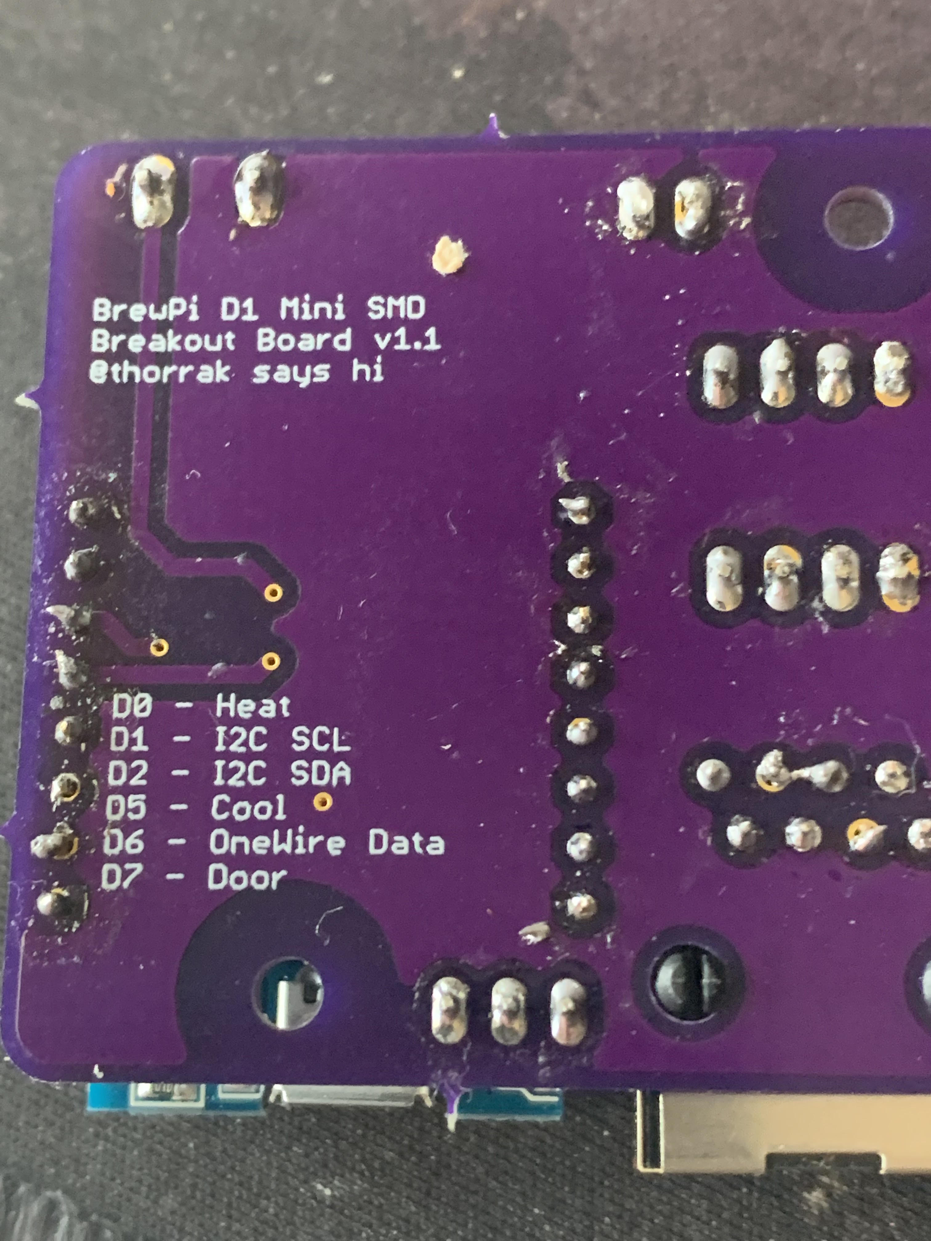
View attachment 764255
Hi Neal,
Wish I had clued in to this yesterday, but it appears the board you are showing here is one designed for surface mount electronics which are mounted below the D1Mini. Those pads you see are where the components are soldered to the board. There was another board that used through hole mounts for the resistors and capacitors, etc required.
I've never fiddled with surface mount stuff before so I can't help with how they attach. All the other stuff mounts through holes either directly or through the use of terminal blocks or male pin headers.
Awful sorry for any confusion I may have caused.
Chris
Lalo_uy
Well-Known Member
The transistors and R under the D1 mini are the level shifters for the 5V display.
There is also the 4k7 pull up for the one wire bus.
There is also the 4k7 pull up for the one wire bus.
alexlark
Well-Known Member
Does anybody know of a location (or page# on a thread) that has a ESPN8266 wiring diagram akin to the ardunio diagram I have used previously. I already have controllers and fermentrack but want to investigate converting my Uno R3 installs to ESPN8266 boards to take advantage of the wireless connection.
The best visual I used for building on the bench was this:Schematic
But using the Fermentrack pinouts for the ESP8266 here:Pinouts
Then power the ESP8266 using micro USB. My build was just this, no shield or breakout board.
Hi folks, I've just started to re-look at my esp8266 brewpi project that I built back in 2017/18
View attachment 737558
I added the buzzer function back using an arduino active buzzer module and successfully built the master branch 0.08 and 0.09 versions, this was on another machine using platformio. I have moved over to another pc running ubuntu and so have done a fresh install of platformio and downloaded a fresh copy the master branch before I started to implement the buzzer again.
Trying to compile gave lots of warnings about SPIFFS depreciating and several errors, one error was solved by making the WiFiManager as a local library and changing platformio.ini to reflect the change the other error was 'i' was not declared in this scope in the function 'bool isValidmDNSName(String)' in brewpi-esp8266.cpp I'm not a good coder so after googling a bit I ended up rewriting to be
this has allowed it to successfully compile but i'm getting corruption on the LCD screen, the last update in the master branch says was to fix lcd corrutionCode:bool isValidmDNSName( const char * mdns_name ) { char c; while ( (c = *mdns_name++) ) if ( c != '.' && !isalnum(c) ) return false; return true; }
View attachment 737553
Should I be using one of the other Dev branches instead ?
Did you find the solution to the LCD corruption? I'm running into the same issue after making a few changes to the firmware.
New version coming (very) soon.Did you find the solution to the LCD corruption? I'm running into the same issue after making a few changes to the firmware.
HI - Soldered as best I could - ESP is flashed and even connected to the Wifi. Have connected it to fermentrack using wifi.
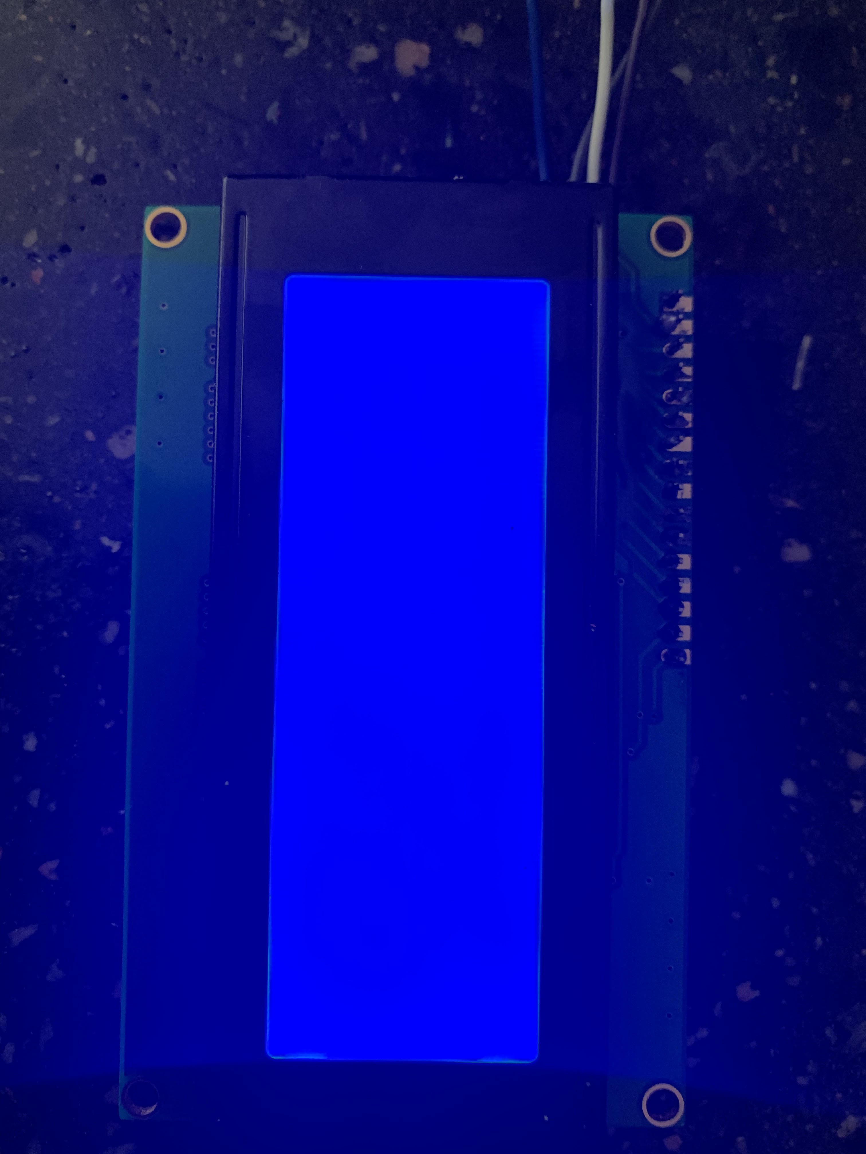
once connected to the board I power the screen on but do not see any image. Am I meant to see the Fridge on screen or do i need to do something else to see this?
once connected to the board I power the screen on but do not see any image. Am I meant to see the Fridge on screen or do i need to do something else to see this?
Attachments


HI - Soldered as best I could - ESP is flashed and even connected to the Wifi. Have connected it to fermentrack using wifi.
once connected to the board I power the screen on but do not see any image. Am I meant to see the Fridge on screen or do i need to do something else to see this?
Have you tried adjusting the pot on the back of the display? Looks to me as if the contrast or brightness is turned way up.

Hope that helps.
Chris
HI - Soldered as best I could - ESP is flashed and even connected to the Wifi. Have connected it to fermentrack using wifi.
once connected to the board I power the screen on but do not see any image. Am I meant to see the Fridge on screen or do i need to do something else to see this?
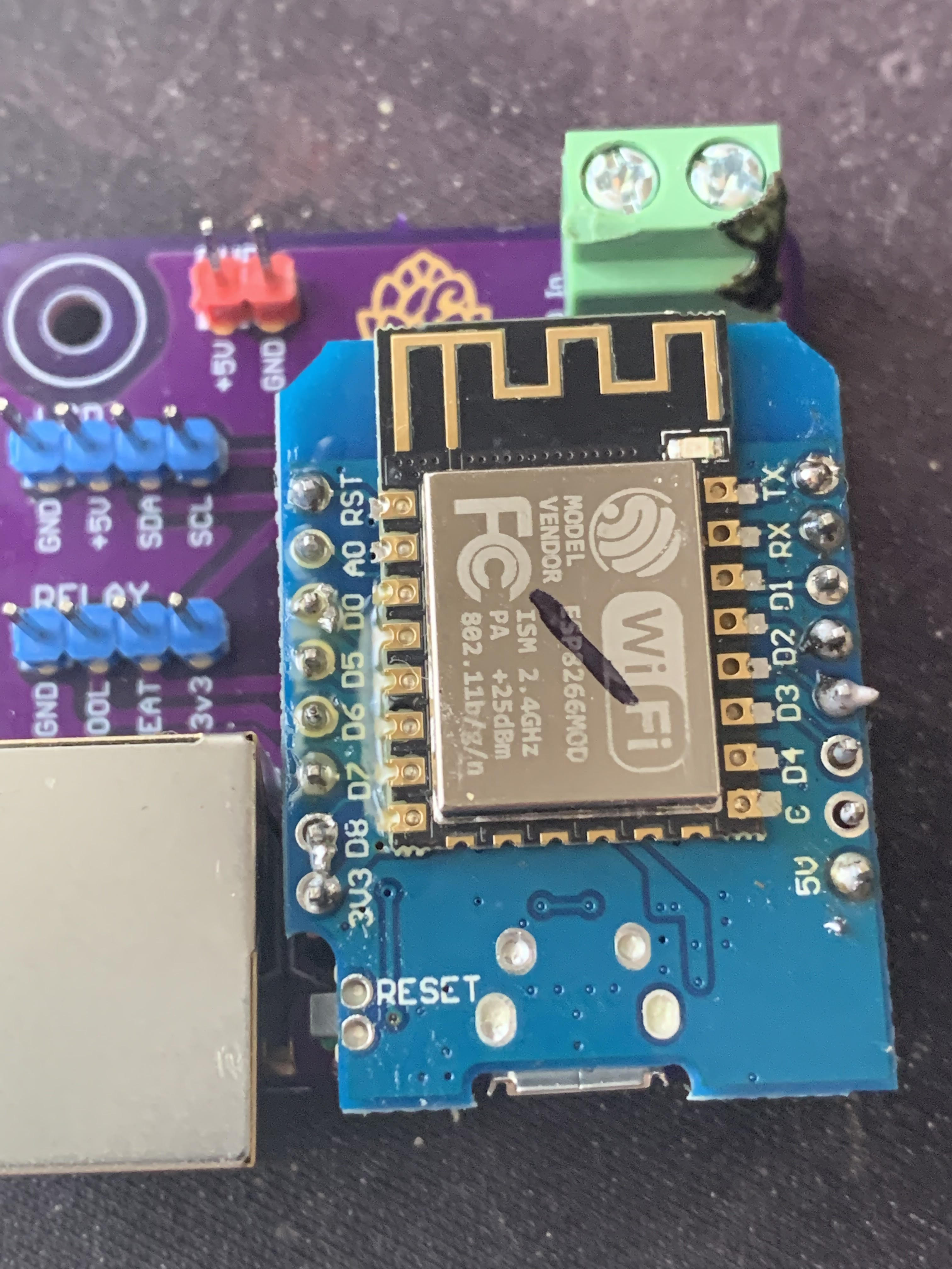
Be careful -- Without checking a schematic, you appear to have a solder bridge between two of the pins for the RJ-45 jack on the bottom of the board. Might be good to clip that if you can.
Four years in the making, it's time to finally release the (beta version of the) latest BrewPi-ESP8266 firmware. This release contains a number of enhancements vs the previous "v11" firmware, including:
As with all of my firmware, The v14 beta firmware is available via BrewFlasher and BrewFlasher Web Edition. This version of the firmware can be directly accessed through the links below:
Good luck, and happy brewing!
- File system initialization enhancements
- Substantial refactoring and upgrades (e.g. JSON handling)
- Unified handling of Serial and WiFi output
- Add ability to add human-readable names to probes (Thanks @speshak)
- Add support for logging to Prometheus (Thanks @speshak)
- Added new “low delay” mode (preliminary glycol support)
- Swap SPIFFS for LittleFS for ESP8266 Builds
- Fix message displayed with temperature control is set to “OFF” (rather than IDLE)
- Added WiFi information command to get signal strength
- Add mandatory confirmation to firmware to prevent accidental EEPROM resets (“network scanner” bug)
- Adds support for TFT LCD Displays
- Adds support for "extended settings" not previously supported in BrewPi
- Adds Bluetooth scanning support
- Adds support for using Tilt Hydrometers as a temperature sensor
- Adds support for using @inkbird wireless temperature sensors (TH2 and TH2-Plus)
- Adds support for using TPLink Kasa WiFi switches
As with all of my firmware, The v14 beta firmware is available via BrewFlasher and BrewFlasher Web Edition. This version of the firmware can be directly accessed through the links below:
- BrewPi-ESP8266 - WiFi
- BrewPi-ESP8266 - WiFi Low Delay (not for use with compressor-based configurations)
- BrewPi-ESP8266 - Serial
- BrewPi-ESP32 WiFi TFT
Good luck, and happy brewing!
DuncB
Well-Known Member
That's a huge amount of work, looking forward to hearing how it goes for everyone.
Does this mean KegScreen is next??!!
lol! 
I notice he hasn't answered yet.... 
Actually, he kinda did
Yeah....looking back, I can see that he did...kinda. 
ChrisThomas
Well-Known Member
There a couple of solder bridges that you'd need to sort out, as @Thorrak said on the RJ45 and there's one on the D1Mini, between 3V3 and D8, you might also have a dry joint on the GND. There could be another couple of dry joints on the surface mount components?HI - Soldered as best I could - ESP is flashed and even connected to the Wifi. Have connected it to fermentrack using wifi.
once connected to the board I power the screen on but do not see any image. Am I meant to see the Fridge on screen or do i need to do something else to see this?
For testing I can recommend @LBussy 's firmware available in BrewFlasher, it's under other, WiFi reset & Sensor/Wiring Test. It's VERY useful when putting your system together and debugging your cabling!
Glad to see the "Low Delay" version for glycol being added. I've been using V.0.11 with glycol in Fridge Const. mode for several years now. what are the specifics of this new "Low Delay" version. Do I still need to use just the frig sensor and set PID values to {0,0,0}, etc.?
I currently have a working Fermentrack setup using the Arduino controller. I am building a ESP8266 controller for the wifi. Can I flash the ESP and test the new controller build with my current fermentrack Pi configuration or would I need a new fermentrack install on the Pi? Im afraid of messing up my current well functioning controller. Can multiple different controllers be used if I wanted the arduino for one fermenter and the ESP for another?
Glad to see the "Low Delay" version for glycol being added. I've been using V.0.11 with glycol in Fridge Const. mode for several years now. what are the specifics of this new "Low Delay" version. Do I still need to use just the frig sensor and set PID values to {0,0,0}, etc.?
All that Low Delay does is change the timings for cooling:
| LowDelay | Normal | |
| MIN_COOL_OFF_TIME | 60 | 300 |
| MIN_HEAT_OFF_TIME | 300 | 300 |
| MIN_COOL_ON_TIME | 20 | 180 |
| MIN_HEAT_ON_TIME | 180 | 180 |
| MIN_COOL_OFF_TIME_FRIDGE_CONSTANT | 60 | 600 |
| MIN_SWITCH_TIME | 600 | 600 |
| COOL_PEAK_DETECT_TIME | 1800 | 1800 |
| HEAT_PEAK_DETECT_TIME | 900 | 900 |
It doesn't change any of the other tuning settings. Eventually I'd like to get glycol mode built, but - as I've mentioned in the past - I don't have a glycol chiller. I did add a "glycol mode" extended setting with these changes as a placeholder for when it eventually gets built, but that setting does nothing at the moment.
I currently have a working Fermentrack setup using the Arduino controller. I am building a ESP8266 controller for the wifi. Can I flash the ESP and test the new controller build with my current fermentrack Pi configuration or would I need a new fermentrack install on the Pi? Im afraid of messing up my current well functioning controller. Can multiple different controllers be used if I wanted the arduino for one fermenter and the ESP for another?
Your existing installation of Fermentrack will work with both an Arduino controller and an ESP8266 controller running the older firmware. The only function of the newer firmware that will not work with your existing installation of Fermentrack is the "eeprom reset" function -- everything else will work perfectly.
I'd start by using your existing installation of Fermentrack -- you can always migrate later.
There a couple of solder bridges that you'd need to sort out, as @Thorrak said on the RJ45 and there's one on the D1Mini, between 3V3 and D8, you might also have a dry joint on the GND. There could be another couple of dry joints on the surface mount components?
For testing I can recommend @LBussy 's firmware available in BrewFlasher, it's under other, WiFi reset & Sensor/Wiring Test. It's VERY useful when putting your system together and debugging your cabling!
Thanks Chris. Sorry for not responding earlier. I accepted in the end the SMD style was above my competency with a soldering Iron and ordered some more boards that had less soldering points and holes instead of surface mountings but i will take heed and try to be as clean as possible.
I have 3 of the surface mounted boards that I do not have the appropriate skills to complete. Anybody want them ? No money needed. I can even send the SMD's I have with them. PM if any help.
I'd prefer to send all 3 to one person if possible.
Update - I have a home for these boards.
I'd prefer to send all 3 to one person if possible.
Update - I have a home for these boards.
Last edited:
Did you have the dockerized version or the non-docker version?I updated my Fermentrack software last night. I now get a "504 Gateway Time-out" I cannot access it on my Pi or remotely. Can someone tell me how to erase the original on my Pi and load the Newest version. Thank you.
chucknorris101
Well-Known Member
- Joined
- Jul 17, 2014
- Messages
- 95
- Reaction score
- 16
how would one migrate from the non-docker to the docker version? will the new auto script move all my settings/etc to the new format?
also for the webflasher, i assume i cant flash them over wifi/need to connect via usb yet?
also for the webflasher, i assume i cant flash them over wifi/need to connect via usb yet?
Does anyone happen to have 3 (or any really) of the Through Hole w/LCD and Dupont - No RJ45 Thorrak PCBs? These guys: thorrak_hardware/D1 - LCD TH Dupont NoRJ.md at master · thorrak/thorrak_hardware
If so, can I buy them from you? Happy to order from OshPark, but figured I'd check to see if anyone had extras from an uncompleted project first.
Second, has anyone mocked up a 3D printed case based around that PCB? I have a big ol' junction box I was going to try and build the setup in, but if there was an existing purpose-built case, that would be lovely. No one wants to see what happens when I get the rotary tool out to try and cut nice squares for the power sockets.
Thanks!
chucknorris101
Well-Known Member
- Joined
- Jul 17, 2014
- Messages
- 95
- Reaction score
- 16
have you tried just unplugging and replugging in the pi? id say if nothing else, you could delete all the indices for fermentrack and run the setup all over again. all you should need to do then is add the brewpi device back, which should already be on your network. lose profiles and names, but it would get you unstuck. If you had a spare SD, could just install everything from scratch to the pi and such and hang onto the existing SD for a 'fix' later?I really need to know how to make this work again. My fermantrack is down and It is locked at 64 degrees, I need to ferment another batch and I need to know how to unistall what is and start fresh or fix what I have.
Similar threads
- Replies
- 10
- Views
- 2K
- Replies
- 3
- Views
- 2K
- Replies
- 7
- Views
- 2K
