Native ESP8266 BrewPi Firmware - WiFi BrewPi, no Arduino needed!

Homebrew Talk - Beer, Wine, Mead, & Cider Brewing Discussion Forum

Help Support Homebrew Talk - Beer, Wine, Mead, & Cider Brewing Discussion Forum:

This site may earn a commission from merchant affiliate links, including eBay, Amazon, and others.
Do you have a Fridge sensor set up? I'm pretty sure you need both a Beer Sensor and a Chamber sensor for the BrewPi to work. Someone please correct me if I'm wrong.
No I dont, only a beer sensor. My first build had both but I didnt think you had to use 2 so wasnt going to bother with this one. I actually thought that could be the issue but dismissed it.

if someone could confirm this please that would be great?
 
Yep, you definitely need a chamber sensor. That's the only one you need, but better to have both the beer and chamber sensors.
 
No I dont, only a beer sensor. My first build had both but I didnt think you had to use 2 so wasnt going to bother with this one. I actually thought that could be the issue but dismissed it.

if someone could confirm this please that would be great?

You will need both if you're going to be running in Beer Constant or Profile mode, however. but perhaps you can use the chamber sensor only to test.
 
You will need both if you're going to be running in Beer Constant or Profile mode, however. but perhaps you can use the chamber sensor only to test.

Damn it. I took the ESP off the board thinking it was faulty and stuffed it in the process of trying to de-solder it.

Anyway Ive brought another ESP and relay. Its a good thing they are both cheap enough on Ebay.
 
Damn it. I took the ESP off the board thinking it was faulty and stuffed it in the process of trying to de-solder it.

Anyway Ive brought another ESP and relay. Its a good thing they are both cheap enough on Ebay.
I would solder female headers on the board and male header pins on the ESP so you don't have this problem again. There is a great risk of ripping off the solder tabs on the PCB if you have to keep messing around with them
 
I would solder female headers on the board and male header pins on the ESP so you don't have this problem again. There is a great risk of ripping off the solder tabs on the PCB if you have to keep messing around with them
I soldered double male headers on the board and then soldered the ESP to the top. I de soldered and sucked out as much solder as I could but I had to cut the pins off. The board and the ESP is probably ok and may work but Ive already ordered a new ESP anyway and it was only $7 on ebay.
 
I need a little help - I'm coming to my wit's end.
I built myself a little controller box with a power supply and relay board and it worked great once. The second time I used it, it blew the 5A fuse in the power switch (this little guy: URBEST Inlet Module Plug 5A Fuse Switch Male Power Socket 10A 250V 3 Pin IEC320 C14 https://www.amazon.com/dp/B00ME5YAPK/ref=cm_sw_r_cp_apa_i_RPwIDbDV5KTST )

I swapped out the fuse and the fermentation continued on without a hiccup.

I started another ferment on Saturday night around 6:00pm. Things were going great until this morning around 9:00am when I checked fermentrack and saw that it had lost connection to the controller. When I got home, I found that the fuse had blown again.

What could be causing the fuse to blow?

I did have some foam come up through the airlock and some liquid made its way down into the thermocouple. Could the temp probe have shorted out?

I'm stumped. Unless itsi the cycling of the relays, I can't think of what could be drawing more than 5 Amps.

Should I just get a slow-blow fuse and see if the problem goes away?

Thanks!

This is the power supply I'm using:

5V Power Supply,PHEVOS 5v 5A Dc Universal Switching Power Supply for Raspberry PI Models,CCTV, Radio, Computer Project,LED Strips Pixel Lights (5V5A) https://www.amazon.com/dp/B07B111B7Y/ref=cm_sw_r_cp_apa_i_N6wIDb20A8GPD

And the relay board:

SainSmart 2-Channel Relay Module https://www.amazon.com/dp/B0057OC6D8/ref=cm_sw_r_cp_apa_i_57wIDbFEV8Q0Q
 
Last edited:
Unfortunately, those are notorious for having problems. Bypass the switch and fuse and just use the plug portion of the unit. Unplug the unit to turn it off.
 
Your fridge draws much more than you think on startup. A slow blow will help but not avoid the issue forever.

If you are curious. look for "RLA" amperage on your compressor or near it. That will tell you why your fuse is blowing.
 
Your fridge draws much more than you think on startup. A slow blow will help but not avoid the issue forever.

If you are curious. look for "RLA" amperage on your compressor or near it. That will tell you why your fuse is blowing.

I know the surge when starting the compressor is greater than the crrent it draws while running, but the compressor's feed doesn't pass through this fuse. The only thing running through the fuse is that 5V power supply. The power supply is feeding the relay board and the ESP8266.
 
That's pretty weird, given the minimal loading that supply shouldn't be pulling more than a couple of amps tops - and even that turn-on peak draw would be for just microseconds while the capacitors charge and the switcher stabilizes.

Maybe it's not well? I'd give slow-blow fuse a try and if that "fixes" the problem I'd be wondering why.

fwiw, I use the 5V/3A version of that same brick in three different control systems - but they're behind 10A fused bulkheads...

Cheers!
 
I'm new to this project and tinkering with pcbs in general and been reading docs for a bit, I'm somewhat lost. Thoraks doc page for pcb and BOM listing mentions a sensor level pcb in the text at the top but then it never appears? Am I missing something?

I'm under the impression I need a main board, an Esp board and a sensor board, and thus far I can't seem to find how all of that is wired together either? I think I saw a schematic in this thread, where do I find those or how are those visible in the documentation?

Is anyone building these and selling them?
You don't need a sensor level PCB- they are called break outboards.
The main PCB will host the ESP8266 and all of the pinouts for all of the connections
Here is what a PCB looks like
img_20170403_111046-jpg.395126
 
You don't need a sensor level PCB- they are called break outboards.
The main PCB will host the ESP8266 and all of the pinouts for all of the connections
Here is what a PCB looks like
img_20170403_111046-jpg.395126
Thanks, makes more sense then on what he was saying in the text now. Is there a schematic for the wiring connections to the different components somewhere?
 
I'm new to this project and tinkering with pcbs in general and been reading docs for a bit, I'm somewhat lost. Thoraks doc page for pcb and BOM listing mentions a sensor level pcb in the text at the top but then it never appears? Am I missing something?

I'm under the impression I need a main board, an Esp board and a sensor board, and thus far I can't seem to find how all of that is wired together either? I think I saw a schematic in this thread, where do I find those or how are those visible in the documentation?

Is anyone building these and selling them?

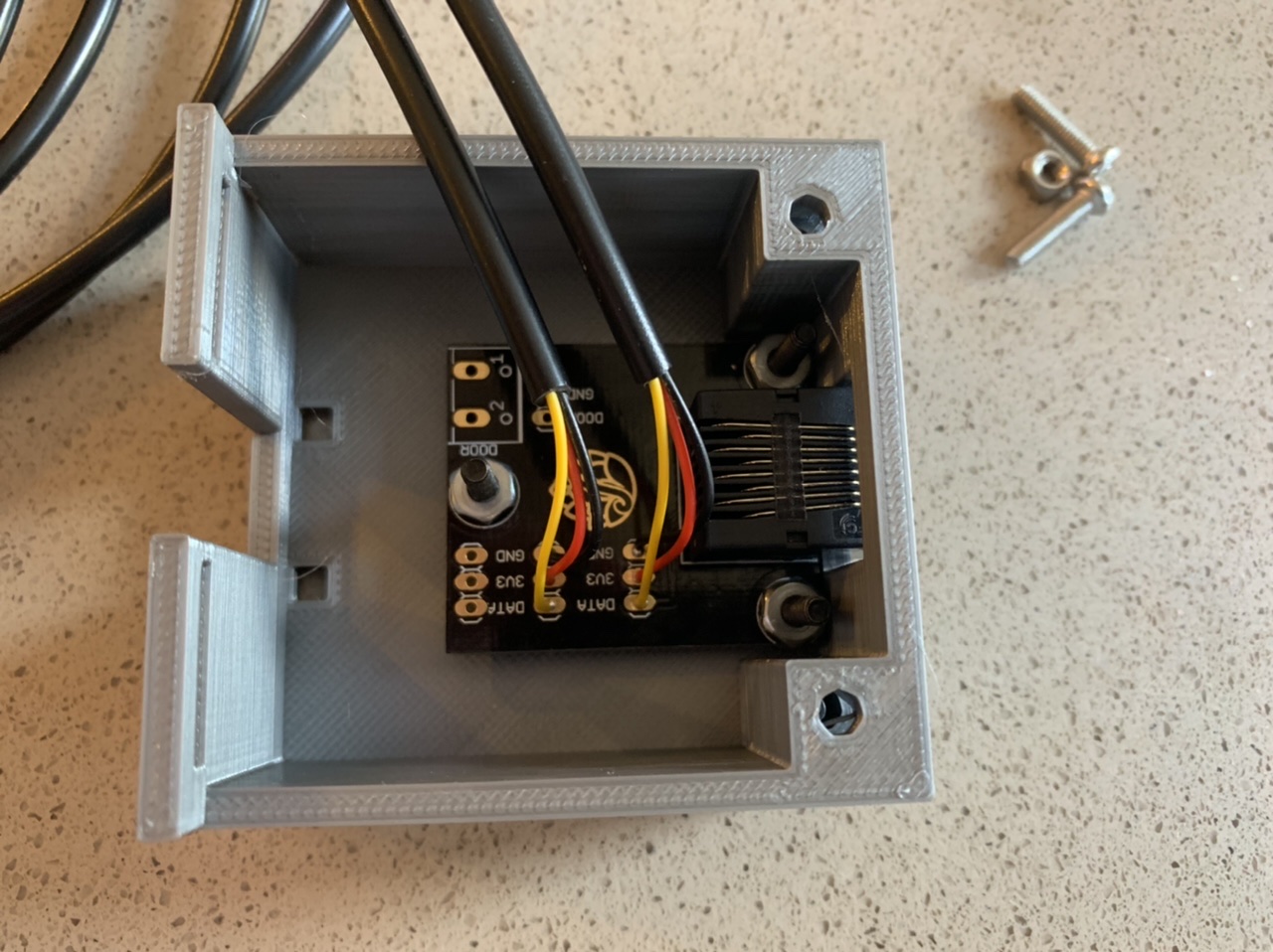
There are two PCBs that I’m currently using for my builds - a board that hosts the ESP8266 (the one @Bigdaddyale was showing in the previous post) and a board that all the temperature sensors connect to. For the latest versions of my PCB designs, you use an Ethernet cable to connect them together.

Both PCBs are optional, but were designed to make builds much easier based on frustrations I’ve had when building controllers on my end. That said, of the two most people looking to do more than just test a build end up using one of the “main” PCBs to wire everything together - the “sensor” breakout PCB is the more likely one to be skipped.

This is what one of the sensor boards looks like from when I photographed a recent build:

5B166F3A-3748-4F46-B8C7-84FF6268ACA0.jpeg


You can see there are a number of unpopulated headers - these are for adding additional sensors if necessary.
 
Thanks, I think I'm understanding now, having the pcb and manual wiring side by side helps a noob see all the same connections on the pcb.

The bottom left of the pcb from @Bigdaddyale is where the ethernet connection goes?

In the pcb pictured there are little nodes at connection points, is that for contacts on the d1 board and ethernet connection? Are these just contact connections or is each point soldered?

When you mention directly connecting the sensors, would that be connecting two sensors directly to the node for the ethernet connection?

Thanks for all your help!
 
@Thorrak

Also, for pcb ordering, I'm looking at the big pcb for lcd, etc. There are ports in the middle that say chan1 and Chan2 hv/lv, how are those wired in?
 
@Thorrak

Also, for pcb ordering, I'm looking at the big pcb for lcd, etc. There are ports in the middle that say chan1 and Chan2 hv/lv, how are those wired in?
That's for another component ( Logic Level Shifter Bi-Directional ) that needs to be soldered on the board. I would go with the LCD Support with DuPont connectors, and surface-mount level converter components with the rj-45 connector.https://pcbs.io/share/8DDk0
 
Admittedly, the self-abuse index can get rather high when working with digital dust ;)
Most of my SSD designs over the last few years used a metric crapton of 0201 passives, and 01005 packages aren't far off (cell phone driven)...

Cheers!
 
Surface-mount is not for older, first-time assemblers IMHO. It’s for young eyes and steady hands. :)

Hey, even us blind squirrels can get lucky and find a nut every now and then!

With some patience, a well lit work space, and a $6 soldering iron, you can do anything......once, ehh...maybe twice, but definitely not more than five times. [emoji51]
 
Me when someone mentions SMD:

upload_2019-10-3_11-47-48.jpg


Unless space is at as premium (and it’s not for these projects) I fail to see why someone would choose the damned things.

Plus, you don’t get the advantage of all those “free” vias. :)
 
How are the control boards themselves powered? The builds have a power cord for deeingthe outlet and relay circuit, but doesn't seem to cover the controller Power.is that over the USB on the d1 board?
 
How are the control boards themselves powered? The builds have a power cord for deeingthe outlet and relay circuit, but doesn't seem to cover the controller Power.is that over the USB on the d1 board?
If you mean the Raspberry Pi as the controller board it is powered separately through its own power plug. The PCB is powered by a 5v wall wort and the DS18B20 break out board is powered by the PCB
 
If you mean the Raspberry Pi as the controller board it is powered separately through its own power plug. The PCB is powered by a 5v wall wort and the DS18B20 break out board is powered by the PCB

Thanks. 5v what connector and amperage? Does the power source come withthe d1? I assume not if it's coming from aliexpress
 
I have Fermentrack running with 3 different minis. Two of the minis are seen by my router with IPs but I can't connect them or ping them thru my Rpi. The third is up and running my ferementer by profile just fine.

1)Is there a numeric range that the IPs need to be for the mini's within?
2)after each reflash attempt the mini's acting as a AP is just available briefly I have to act fast, within 1 min, to set up the wifi. Is this normal?
3) Is there a disconnecting, repowering or rebooting sequence for the Rpi, Mini's and router that is optimal to get them to play nice with each other? My router is slow to get back up and running.
 
Damn it. I took the ESP off the board thinking it was faulty and stuffed it in the process of trying to de-solder it.

Anyway Ive brought another ESP and relay. Its a good thing they are both cheap enough on Ebay.

Not true, what you need is one sensor configured as "Fridge" - I use only one in my kegarators - works just fine.

Storage.JPG
 
Right - for Fridge Constant you only need the Fridge probe as no additional information is needed by BrewPi in that mode.
But for Profiles or Beer Constant you need both the Fridge probe and the Beer probe.
The Room probe isn't referenced by the control code...or anything else afaik...

Cheers!
 
Right - for Fridge Constant you only need the Fridge probe as no additional information is needed by BrewPi in that mode.
But for Profiles or Beer Constant you need both the Fridge probe and the Beer probe.
The Room probe isn't referenced by the control code...or anything else afaik...

Cheers!
Ok cheers for that Ill just use the one probe set as fridge but put it inside my thermowell.
 
Is there instructions on enabling bluetooth for the Tilt? I keep getting error "Connection type Bluetooth packages for python have not been installed. Tilt Hydrometers cannot be connected via Bluetooth." on my Raspberry Pi 3 and Arduino Uno R3.

Thanks
 
Is there instructions on enabling bluetooth for the Tilt? I keep getting error "Connection type Bluetooth packages for python have not been installed. Tilt Hydrometers cannot be connected via Bluetooth." on my Raspberry Pi 3 and Arduino Uno R3.

Thanks

This thread is for the ESP8266 BrewPi firmware - are you trying to connect a Tilt to Fermentrack?
 

Latest posts

Back
Top