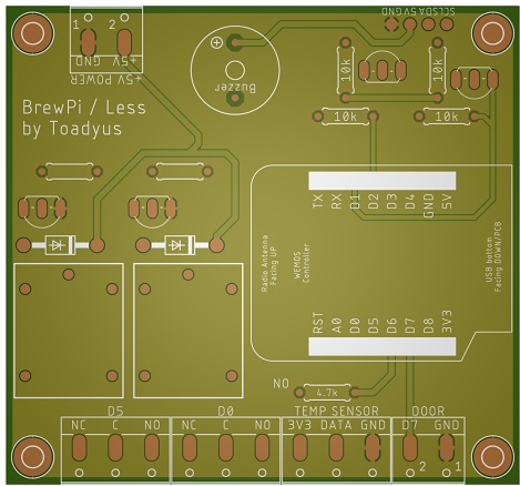
Yes.Okay so swap the pins on the relay as circled '(or the Wemos end) and then set the probes to inverted in Fermentrack?
You are using an out of date browser. It may not display this or other websites correctly.
You should upgrade or use an alternative browser.
You should upgrade or use an alternative browser.
Native ESP8266 BrewPi Firmware - WiFi BrewPi, no Arduino needed!
- Thread starter Thorrak
- Start date

Help Support Homebrew Talk:
This site may earn a commission from merchant affiliate
links, including eBay, Amazon, and others.
You've got high voltage on the board now - why not just put the power supply on there?@LBussy This was my idea for the AIO board. Pretty much got it built just going over some design ideas and I'll probably change it from 12v to 5v or leave it and remove the buck 3a.
Also, since you're going to the trouble to make a board, you can roll your own level converter instead of using the SparkFun-ish daughterboard:
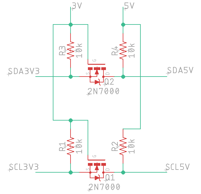
I'd probably also suggest avoiding SMD's as they are tougher for a lot of folks to work with and really offer no advantages here - you've got more than enough room.
Bigdaddyale
Well-Known Member
Not the temp. probes but the relays you want to set to invertedOkay so swap the pins on the relay as circled '(or the Wemos end) and then set the probes to inverted in Fermentrack? Just making sure Ive got this correct?
View attachment 636925
Oh okay yep I meant the relays. Thanks heaps to everyone for your help.Not the temp. probes but the relays you want to set to inverted
At least Im not the guy in Sydney who drove a van into 2 parked police cars and when they caught him he had $250M worth of Ice in the back.

He had one job and now hes no doubt a dead man.
Bigdaddyale
Well-Known Member
Did you get your board yet? Should be anytime now.
No not yet. Im thinking sometime this week.Did you get your board yet? Should be anytime now.

$719.00
$799.00
EdgeStar KC2000TWIN Full Size Dual Tap Kegerator & Draft Beer Dispenser - Black
Amazon.com

$33.99 ($17.00 / Count)
$41.99 ($21.00 / Count)
2 Pack 1 Gallon Large Fermentation Jars with 3 Airlocks and 2 SCREW Lids(100% Airtight Heavy Duty Lid w Silicone) - Wide Mouth Glass Jars w Scale Mark - Pickle Jars for Sauerkraut, Sourdough Starter
Qianfenie Direct

$172.35
2 Inch Tri Clamp Keg Manifold With Ball Lock Posts, Pressure Gauge, PRV (0-30 PSI) – Homebrew, Fermentation, Kegging System
wuhanshijiayangzhiyimaoyiyouxiangongsi

$33.98
DYKWSWYX Heavy Duty Brewing Gloves (1 Pair) - 55CM Long Chemical Resistant Plastic Gloves for Beer & Wine Making, Cleaning, Homebrew Equipment Protection
wuhanshijiayangzhiyimaoyiyouxiangongsi

$58.16
HUIZHUGS Brewing Equipment Keg Ball Lock Faucet 30cm Reinforced Silicone Hose Secondary Fermentation Homebrew Kegging Brewing Equipment
xiangshuizhenzhanglingfengshop

$76.92 ($2,179.04 / Ounce)
Brewing accessories 1.5" Tri Clamp to Ball Lock Post Liquid Gas Homebrew Kegging Fermentation Parts Brewer Hardware SUS304 Brewing accessories(Gas Hose Barb)
chuhanhandianzishangwu

$49.95 ($0.08 / Fl Oz)
$52.99 ($0.08 / Fl Oz)
Brewer's Best - 1073 - Home Brew Beer Ingredient Kit (5 gallon), (Blueberry Honey Ale) Golden
Amazon.com
![Craft A Brew - Safale S-04 Dry Yeast - Fermentis - English Ale Dry Yeast - For English and American Ales and Hard Apple Ciders - Ingredients for Home Brewing - Beer Making Supplies - [1 Pack]](https://m.media-amazon.com/images/I/41fVGNh6JfL._SL500_.jpg)
$6.95 ($17.38 / Ounce)
$7.47 ($18.68 / Ounce)
Craft A Brew - Safale S-04 Dry Yeast - Fermentis - English Ale Dry Yeast - For English and American Ales and Hard Apple Ciders - Ingredients for Home Brewing - Beer Making Supplies - [1 Pack]
Hobby Homebrew

$22.00 ($623.23 / Ounce)
AMZLMPKNTW Ball Lock Sample Faucet 30cm Reinforced Silicone Hose Secondary Fermentation Homebrew Kegging joyful
无为中南商贸有限公司

$53.24
1pc Hose Barb/MFL 1.5" Tri Clamp to Ball Lock Post Liquid Gas Homebrew Kegging Fermentation Parts Brewer Hardware SUS304(Gas MFL)
Guangshui Weilu You Trading Co., Ltd

$7.79 ($7.79 / Count)
Craft A Brew - LalBrew Voss™ - Kveik Ale Yeast - For Craft Lagers - Ingredients for Home Brewing - Beer Making Supplies - (1 Pack)
Craft a Brew

$176.97
1pc Commercial Keg Manifold 2" Tri Clamp,Ball Lock Tapping Head,Pressure Gauge/Adjustable PRV for Kegging,Fermentation Control
hanhanbaihuoxiaoshoudian

$479.00
$559.00
EdgeStar KC1000SS Craft Brew Kegerator for 1/6 Barrel and Cornelius Kegs
Amazon.com

$20.94
$29.99
The Brew Your Own Big Book of Clone Recipes: Featuring 300 Homebrew Recipes from Your Favorite Breweries
Amazon.com

$44.99
$49.95
Craft A Brew - Mead Making Kit – Reusable Make Your Own Mead Kit – Yields 1 Gallon of Mead
Craft a Brew

$53.24
1pc Hose Barb/MFL 1.5" Tri Clamp to Ball Lock Post Liquid Gas Homebrew Kegging Fermentation Parts Brewer Hardware SUS304(Liquid Hose Barb)
yunchengshiyanhuqucuichendianzishangwuyouxiangongsi
Lalo_uy
Well-Known Member
This is my BPL board, all from scratch.
It uses a switching 5V PSU module and 5V relay.
LM1111 reg to 3V .
Changing some jumpers will deliver AC or just dry contacts.
If any one is interested in eagle files let me know.

It uses a switching 5V PSU module and 5V relay.
LM1111 reg to 3V .
Changing some jumpers will deliver AC or just dry contacts.
If any one is interested in eagle files let me know.

Thanks gents for all your help. Switched the pins over on the board and changed the relays to inverted and all is working fine now. In idle mode the relays are both off now instead of on.
Thanks again.
Thanks again.
Thank you! By doing two things backwards you found a new and interesting way to generate confusion.Thanks gents for all your help. Switched the pins over on the board and changed the relays to inverted and all is working fine now. In idle mode the relays are both off now instead of on.
Honestly, it was one of those things where I was in the shower and thought "that's it!" ..... and then I logged on to see @day_trippr beat me to the bunch. Gotta get up early I tell ya!
toadyus
Well-Known Member
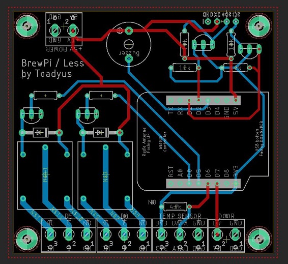
That looks good to me without seeing the schematic of course. It's hard to find a glamourous way to route the traces for that logic shifter, isn't it?How does this look? Moved some things around and added your idea for the Logic level converter.
So just musing here, not trying to be critical, I am thinking about the actual application in situ:
- Your high voltage is right next to the low voltage. It's not hard to imagine that going wrong. In the US that would not meet code in most jurisdictions. We're not necessarily constrained by that, but if it ever caused a fire it would be easy for insurance to deny a claim.
- Imagining a case around this, all of the low voltage should be on one side and high voltage on the other. It's a crapshoot whether you put the power supply on the "back" side to facilitate a power supply internal to the case, or on the same side as the other low voltage. The USB connection should be on the low voltage side for sure in the case of someone using a serial connection or USB power.
- An airgap around the high voltage area would be a very cheap bit of insurance. Who knows about the dielectric strength of the solder mask coming from a random manufacturing shop in China.
- Having the RJ45 for a breakout is VERY handy, you've probably got more than enough room for that too.
toadyus
Well-Known Member
That looks good to me without seeing the schematic of course. It's hard to find a glamourous way to route the traces for that logic shifter, isn't it?
So just musing here, not trying to be critical, I am thinking about the actual application in situ:
Like I said, not intending to be critical. Well, I guess technically this is the definition of "critical" but I'm just trying to help you improve it.
- Your high voltage is right next to the low voltage. It's not hard to imagine that going wrong. In the US that would not meet code in most jurisdictions. We're not necessarily constrained by that, but if it ever caused a fire it would be easy for insurance to deny a claim.
- Imagining a case around this, all of the low voltage should be on one side and high voltage on the other. It's a crapshoot whether you put the power supply on the "back" side to facilitate a power supply internal to the case, or on the same side as the other low voltage. The USB connection should be on the low voltage side for sure in the case of someone using a serial connection or USB power.
- An airgap around the high voltage area would be a very cheap bit of insurance. Who knows about the dielectric strength of the solder mask coming from a random manufacturing shop in China.
- Having the RJ45 for a breakout is VERY handy, you've probably got more than enough room for that too.

Being critical when dealing with electricity is a good thing and awesome catch on the 5V / 3.3V!! Oh my god Yes trying to route the traces for the logical shifter was "fun"!! Here's an update after the changes and yes I will be sharing the gerbers for this project once it's tested.
Lalo_uy
Well-Known Member
Instead of using the level shifter you can convert the LCD to 5/3V mix as explained here:
https://www.instructables.com/id/Raspberry-Pi-Using-1-I2C-LCD-Backpacks-for-1602-Sc/
Just a cut and 1 more pin to send 5V to LCD & keep I2C board at 3,3V.
I try it and works like a charm:
https://www.instructables.com/id/Raspberry-Pi-Using-1-I2C-LCD-Backpacks-for-1602-Sc/
Just a cut and 1 more pin to send 5V to LCD & keep I2C board at 3,3V.
I try it and works like a charm:
Attachments
It's not the LCD, it's the signals in from the sensors.
JnR_NaT
Active Member
- Joined
- Feb 17, 2019
- Messages
- 40
- Reaction score
- 10
This esp8266 is doing my head in. I flashed the esp and configured it for my WiFi. But then no matter how I double/triple tap the rest button i can not get the ESP AP to start so i can configure it. Is there some magic button press that needs to be done?
Has this controller had firmware flashed to it previously?
JDL
Well-Known Member
Need help with a second esp8266 controller. I have a working controller and tested the build with that working esp8266 and everything worked perfectly.
Upfront I must admit I started this second one about 6 months ago and am not sure where I left off with it.
When it boots it runs through the test software that checks the sensors and turns on cooling/heating relays and such and completes with Done with tests. It says the device address is 27 during the test as well. So I obviously flashed this at some point in the past to even be able to run the tests such as that.
I cannot connect to the board in anyway to flash the board at all again, have tried a usb connector to a computer, tried to connect to its wifi but the captive portal does not appear. I have tried the reset button on it as well but that also does not seem to reset the WiFi AP.
I am sure I am missing something obvious here, any help is greatly appreciated. Until then I will keep looking through this and other posts on the subject.
Thanks,
Jeff
I cannot connect to the board in anyway to flash the board at all again, have tried a usb connector to a computer, tried to connect to its wifi but the captive portal does not appear. I have tried the reset button on it as well but that also does not seem to reset the WiFi AP.
Thanks,
Jeff
I would try a different USB cable. Some USB cables are for charging only. You need one that is for charging and data. I would check that first.
stbernts
Well-Known Member
- Joined
- May 20, 2016
- Messages
- 257
- Reaction score
- 43
Need help with a second esp8266 controller. I have a working controller and tested the build with that working esp8266 and everything worked perfectly.
Upfront I must admit I started this second one about 6 months ago and am not sure where I left off with it.
When it boots it runs through the test software that checks the sensors and turns on cooling/heating relays and such and completes with Done with tests. It says the device address is 27 during the test as well. So I obviously flashed this at some point in the past to even be able to run the tests such as that.
I cannot connect to the board in anyway to flash the board at all again, have tried a usb connector to a computer, tried to connect to its wifi but the captive portal does not appear. I have tried the reset button on it as well but that also does not seem to reset the WiFi AP.
I am sure I am missing something obvious here, any help is greatly appreciated. Until then I will keep looking through this and other posts on the subject.
Thanks,
Jeff
There is a reset firmware on the github, download all of them - run them all, reset the esp between each flash, in the end it should be "blank"
JDL
Well-Known Member
Thanks garzlok and stbernts. Both ideas worked and I was able to get it reset and communicating with it. Doing a test on it now and hopefully will have second wireless box up and running.
Jeff
Jeff
I have worked with the other authors/developers/maintainers and have developed a comparison document between the various BrewPi variants. Here it is - errors are mine.
stbernts
Well-Known Member
- Joined
- May 20, 2016
- Messages
- 257
- Reaction score
- 43
I have worked with the other authors/developers/maintainers and have developed a comparison document between the various BrewPi variants. Here it is - errors are mine.
Seems iSpindel is missing on the feature list for Fermentrack on that site.
Key Description/Difference from BrewPi:
- Adheres to the spirit/look/feel of the original BrewPi
- Updated for current versions of Python and PHP
- Tools rewritten for a streamlined/one script install
- Multi-chamber support
- Bluetooth and WiFi capable
- Tilt support
- Adheres to the spirit/look/feel of the original BrewPi
You'd think @Thorrak would have mentioned that.Seems iSpindel is missing on the feature list for Fermentrack on that site.
So long as it works, I'll add it.
RedwoodMonkey
Member
Hello! I'm new here. I got a raspberry pi and installed Fermentrack on the latest Raspbian. I had trouble getting my Tilt to connect, as it says Bluetooth wasn't setup. I think this was a few things:
pybluez failed to compile:
bluez/btmodule.h:5:10: fatal error: bluetooth/bluetooth.h: No such file or directory
#include <bluetooth/bluetooth.h>
^~~~~~~~~~~~~~~~~~~~~~~
So, I installed the dev version of libbluetooth:
sudo apt-get install libbluetooth-dev
That got it to compile, but I was still having trouble adding the Tilt. I did this step cribbed from the install notes and that seemed to get me going:
sudo setcap cap_net_raw+eip /home/fermentrack/venv/bin/python
...but I think the main problem was the compile error failing earlier in the process.
Any thoughts about updating the install script to install libbluetooth-dev?
Is this thread the best place to post questions, comments and ideas?
I'm thinking about playing around with the source, but I don't know python. I'd like to add support for calculating the ABV, and % attenuation. Maybe relay to a Google spreadsheet.
-corbin
RedwoodMonkey
Member
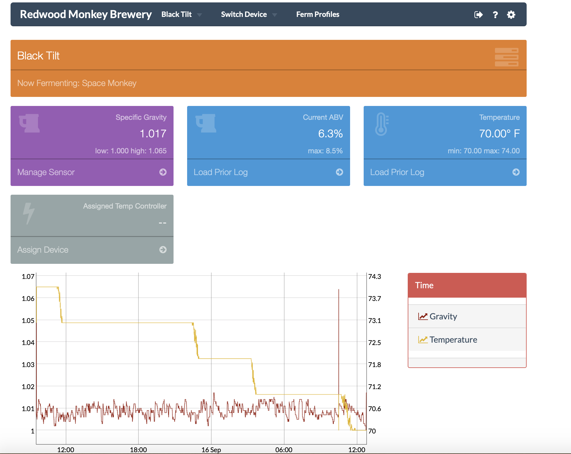
So far, this is what I've added to my fork. I use the Dygraph to figure out the min/max of stuff, and do some simple calculations. I'm super new to python and javascript, so I'm a bit slow, but it is now showing me the info I want to see.
Current ABV is based off the sensor's current gravity reading (lowest) and the highest value it ever reached. I don't have a lot of data yet for this test beer (it is almost done fermenting), but it will probably be better to average the highest for a short period at the start of fermentation.
Max ABV is based off the max/min values it ever reached; my tilt is floating on a lot of hop material right now and is reading lower than it should.
Corbin
RedwoodMonkey
Member
Ironically (based on the name), before I ran across Fermentrack, I created a macOS app called "FermentationTracker" -- I designed it to keep track of beers I brewed and track the fermentation with a Tilt.
FWIW: https://github.com/corbinstreehouse/FermentationTracker
I think I'm going to abandon it and work on making Fermentrack do what I want it to do.
Things I'd like to have it do: Beer-centric organization -- tracking the fermentation should revolve around the beer, and I want to save that information for later reference. I potentially want it to (somehow) link back to the BeerSmith document I used to create the beer.
-corbin
Hi Corbin.
I’m not a Fermentrack user, however I’d suspect Thorrak carried over the ability to start and stop a brew. That would give you the raw ability to save off a beer when done.
I’m not a Fermentrack user, however I’d suspect Thorrak carried over the ability to start and stop a brew. That would give you the raw ability to save off a beer when done.
Not sure how I double posted ....
RedwoodMonkey
Member
Ye
Yeah - through the use of log files. It just isn’t intuitive; I want some sort of sidebar with a list of all previous beers. It looks easy for me to add; I haven’t gotten to it yet.
Hi Corbin.
I’m not a Fermentrack user, however I’d suspect Thorrak carried over the ability to start and stop a brew. That would give you the raw ability to save off a beer when done.
Yeah - through the use of log files. It just isn’t intuitive; I want some sort of sidebar with a list of all previous beers. It looks easy for me to add; I haven’t gotten to it yet.
If you like to tinker, check out
prasathmani/tinyfilemanager on GitHub. It’s something I intend to incorporate into BrewPi as the ability to browse/view/edit random files is pretty common.
prasathmani/tinyfilemanager on GitHub. It’s something I intend to incorporate into BrewPi as the ability to browse/view/edit random files is pretty common.
Howdy. rewers. Im making my second brewpi temp controller and all was going well until.... I plugged it ion with the power switch turned on at the power point. It sparked at the connection and now when I turn it on both relay LEDs light up and at the same time and supply power to the sockets. I thought it might be the actual relay so I swapped it out for the relay in my other controller and Im getting the same problem. So does this mean the ESP is stuffed? is there another way to double check it?
At the least, it sounds like the two GPIO pins driving the relay optocouplers are sitting in a low state, hence the relays being active.
Have you tried reloading the firmware? Or at least hooked it up to something (IDE) to verify there's some form of "life" inside the ESP?
Cheers!
Have you tried reloading the firmware? Or at least hooked it up to something (IDE) to verify there's some form of "life" inside the ESP?
Cheers!
At the least, it sounds like the two GPIO pins driving the relay optocouplers are sitting in a low state, hence the relays being active.
Have you tried reloading the firmware? Or at least hooked it up to something (IDE) to verify there's some form of "life" inside the ESP?
Cheers!
Ok looks like its the relay. (When you swap something out make sure you have actually swapped them over..LOL) So my first relay wont work in either temp controller.
However Ive noticed that when I set a temperature in fermentrack even though it says "Temperature control settings updated for fermenter 2" The LCD text says Idling and doesn't start to cool/heat
Does it say "Idle" or does it say "Wait to Cool"? I run into the latter any time I have to reboot any Arduino at the end of my classic BrewPi setup - there's a ten minute short-cycle timer that has to expire before it will turn on a cooler...
Cheers!
Cheers!
I can set beer constant to 30C (Current temp is 17C) or to 6C and it still just says Idling for …. Instead of saying heating or cooling. Does this mean the ESP and the relay are both shot? I did reflash the ESP and added it again in Fermentrack and it all worked fine.
No definitely says idling...Does it say "Idle" or does it say "Wait to Cool"? I run into the latter any time I have to reboot any Arduino at the end of my classic BrewPi setup - there's a ten minute short-cycle timer that has to expire before it will turn on a cooler...
Cheers!

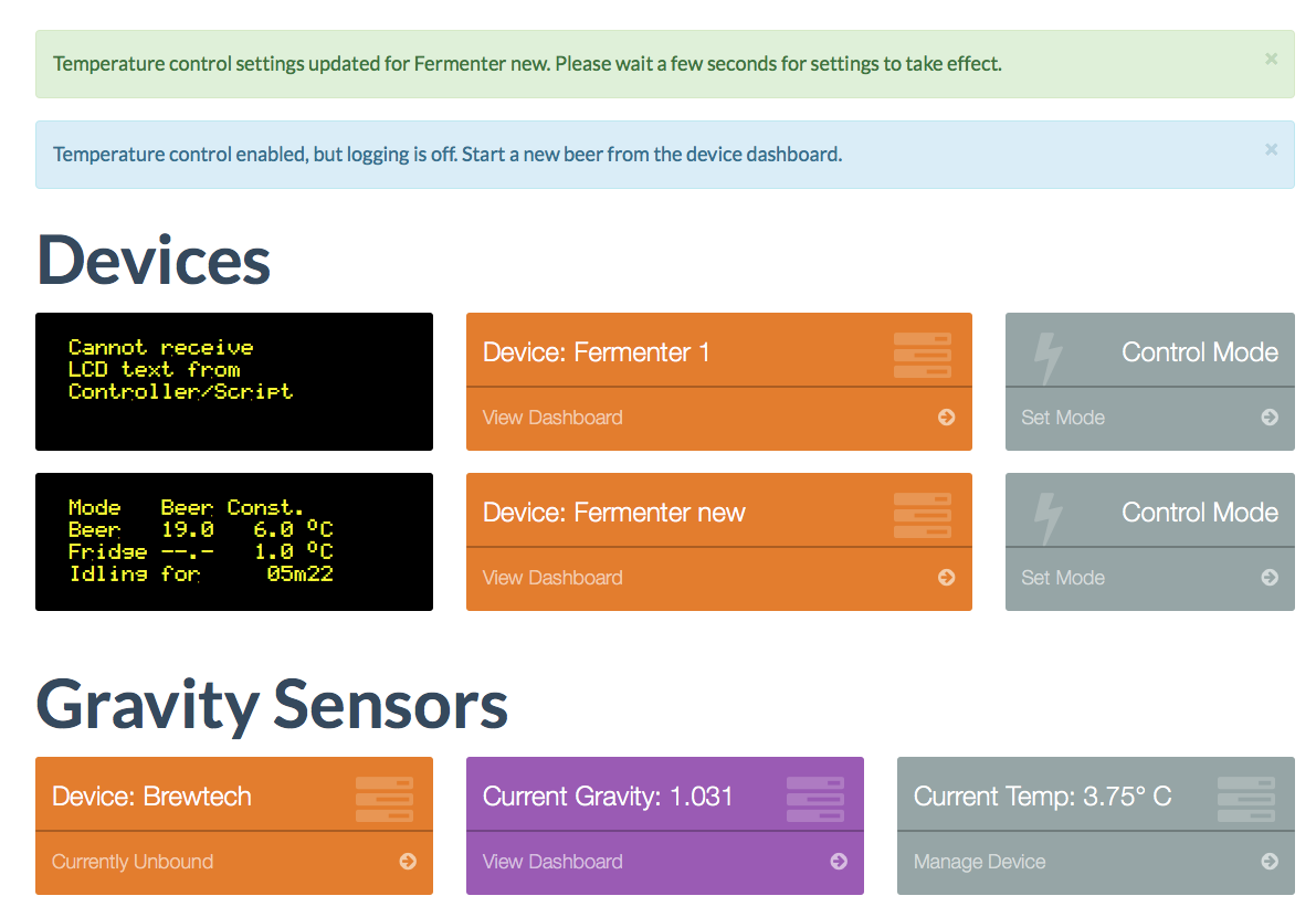

Don't know what this means but when I debug it fails the controller response test. The ESP is soldered onto a PCB. Maybe Ill solder it onto another one and see if it works perhaps?
EDIT:- Controller response test fails for fermenter 1 also but it still displays waiting to heat/cool as per normal and works fine.
EDIT:- Controller response test fails for fermenter 1 also but it still displays waiting to heat/cool as per normal and works fine.
Last edited:
So I've added my tilt and bound it to my Arduino-based temperature controller, but it doesn't seem to be logging any of the data on the graph. Is there a setting I'm missing somewhere to display that info on the graph?
No definitely says idling...
Do you have a Fridge sensor set up? I'm pretty sure you need both a Beer Sensor and a Chamber sensor for the BrewPi to work. Someone please correct me if I'm wrong.
Similar threads
- Replies
- 10
- Views
- 2K
- Replies
- 3
- Views
- 2K
- Replies
- 7
- Views
- 2K


