Native ESP8266 BrewPi Firmware - WiFi BrewPi, no Arduino needed!

Homebrew Talk - Beer, Wine, Mead, & Cider Brewing Discussion Forum

Help Support Homebrew Talk - Beer, Wine, Mead, & Cider Brewing Discussion Forum:

This site may earn a commission from merchant affiliate links, including eBay, Amazon, and others.
I see the change, but can you explain why it is better? I understand electricity like I understand plumbing and baking, so lots of things obvious to electronic hobbyists go right over my head.


Totally lost me, I don't know pullup, VCC or JVCC. I'm googling now, but a simple explanation would be helpful. It sounds like you're saying it's a way to trigger the coils with 5v vs. 3.3v as originally shown, which may help longevity by not burning out the regulator. Which sounds good.

EDIT: I think I get it now. Pulling the jumper separates the relays into basically 3 parts: the signal from the board which basically just fires an LED which would still be 3.3 V, the low voltage side of the relays which is 5V, and the high voltage side of the relays would all be separated. So basically instead of powering and triggering the relays from the ESP, I would pull 5V from the power supply before it goes into the ESP. And if I understood my googling this would require NOT grounding from ESP to the relay board as shown via the euro connector, but rather ground the relays to the ground from the 5V supply?

Leaving off J5, this drawing fairly represents most dual channel relay modules.

2cha2.jpg


With the jumper cap removed from the three pin header one has the option then of running 3.3V, GND, and the two GPIO signals to the four pin header, and 5V and GND to the three pin header (avoiding the pin labeled VCC). That takes the coil loads off the pissant 3.3V linear regulator on the esp module while providing a 3.3V reference for the signal side pull-up resistors, which removes any chance of frying the Arduino...

Cheers!
 

Attachments

  • upload_2019-11-7_13-54-19.jpeg
    upload_2019-11-7_13-54-19.jpeg
    4.2 KB · Views: 42
So, I tried getting all this working a few months ago, and I gave up. Hitting this again, and I’m mostly there. I have a BrewPi+ESP8266 setup, along with an iSpindel. I’ve got both configured and working except for one piece. The iSpindel’s communication with the controller.

I’ve got screenshots below, and you can see that both fermentrack and the controller both see the temperature reading of the iSpindel. The problem comes in with setting that iSpindel as the beer sensor. If I go in to manage the controller, the iSpindel doesn’t show up at all as an option to even pick it as that sensor.

Any ideas on what I can try? Like I said, it’s been months since I tried initially setting this up. The iSpindel I flashed and started over. But, the firmware on the controller is older. I didn’t want to flash that and start over if I didn’t have to.

Thanks for any help you can provide.

IMG_20191106_130311_1-e1573152408910.jpg
IMG_20191106_095521-e1573152457497.jpg

@Thorrak will need to confirm, but I don't believe you can use the iSpindel's temp sensor in the Fermentrack controller. You'll need a separate beer and chamber sensor.
 
@Thorrak will need to confirm, but I don't believe you can use the iSpindel's temp sensor in the Fermentrack controller. You'll need a separate beer and chamber sensor.
The ispindel’s temp sensor doesn’t poll frequently enough to be used as a beer sensor, so support doesn’t exist in either Fermentrack or the firmware for using an iSpindel as a beer temp sensor for the BrewPi controller.
 
Last edited:
So here's some reading I did on wiring of relays. I note that @Thorrak hasn't found it necessary to do any of this, which is a pretty strong endorsement. @day_trippr is suggesting both 3.3v and 5v to the relay, as well as two grounds. Here are some posts by Paul__B that seem to make a good case for not only supplying 5v and ground from the supply, but not grounding back to the board alongside the relay inputs. I found numerous sources that suggest the same, just quoted these because they seem quotable, and the pictures magically copied over :).
Of course I'm not qualified to really have an opinion, just sharing what I found.
Re: NodeMCU with 5V relay #17 Jul 19, 2019, 06:31 pm
I thought you might ask these things.
smiley-lol.png


Here is the per-relay circuit of the relay board:
lMYtu.jpg


Note the input circuit of the opto-coupler. It connects from "IN0" to "VCC". It has nothing whatsoever to do with ground - the ground is only for the relay power so you connect ground only to the relay power - using the terminal in the triple header.

Secondly, you have a green LED with a voltage drop of 2 V or more (the 1.8 on the diagram is rather conservative
smiley-roll.png
) in series with a optocoupler (IR) LED of 1.3 V or so drop. That would easily total 3.3 V without the resistor, so you need more than 3.3 V to reliably actuate it. So "VCC" must be connected to 5 V, not 3.3 V.

Note that the two LEDs in series will definitely not conduct below about 2.5 V or so, so with 5 V on "VCC", no more than 2.5 V can ever appear on "IN0" so there is no risk in doing so, of applying any voltage greater than that, to the ESP8266.

Quote from: larrywal32 on Jul 19, 2019, 06:10 pm
if the signal circuits are really isolated from the relay circuit, then wouldn't the signal circuit need a ground?

A critical concept here regarding electronics and logic. A circuit must be a complete circuit, but logic does not always reference to ground. "Active-LOW" logic references instead, to Vcc.
smiley-cool.png
and
Re: single 5V power source for ESP8266 and relay rack #9 Jan 14, 2019, 02:42 am


Quote from: DaleSchultz on Jan 13, 2019, 11:38 pm
I did in fact already connect the VCC next to the in pins to the 3V3 of the NodeMCU and I also bound all grounds together and it seemed to work. Since only one power supply is in play, I thought that all the grounds should be at the same level anyway, no?

Ah Here's the trick.
smiley-lol.png


You presently have the mind-set of doing your house wiring. You connect one thing to another with a wire, the current flows, the light goes on. What's the problem?

Well, we are not doing your house wiring here!
smiley-eek.png
We are working with parts which operate at 16 MHz, that is Radio Frequency and a piece of wire is an antenna capable of receiving and transmitting signals. It is an inductor, albeit small.

Again and again here, we see the problems when someone innocently connects one of these relay boards to an Arduino of sorts (because of course, this is the Arduino forum), writes their code, the relays click in step and the indicator LEDs light, but then they connect the relays to their power devices and suddenly and unexpectedly the code starts crashing.
smiley-eek.png
What happened?

Well, the relays switching generate rapid transients - current impulses in the wiring which are transmitted inductively from one part of the wiring to another where there are small voltage drops across the wires.

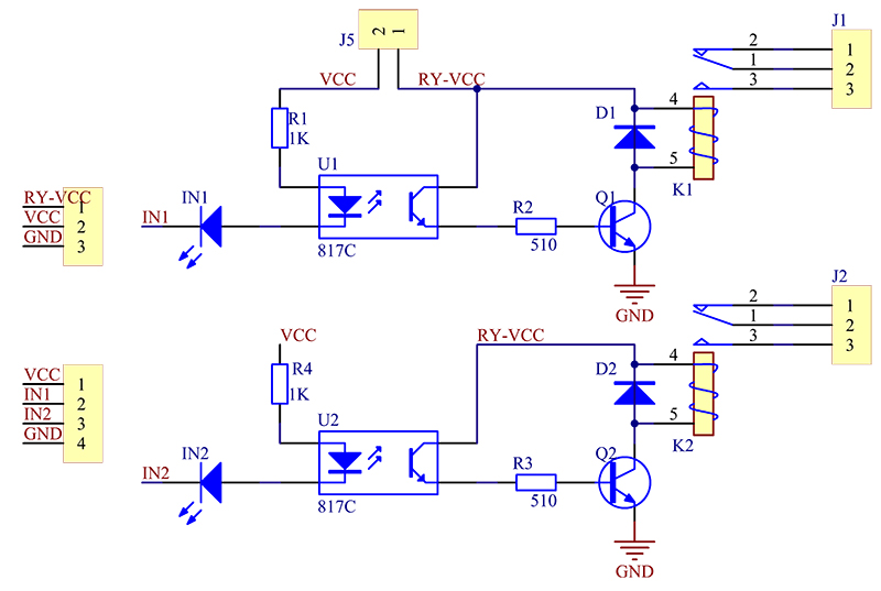
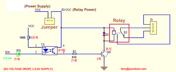
To avoid this, the relay board provides some optical isolation, but to actually make use of this, it is necessary to actually keep the input circuit to the Arduino/ NodeMCU separate from that carrying the relay current, and to prevent inductive pick-up from one to the other.

Quote from: DaleSchultz on Jan 13, 2019, 11:38 pm
If I connect +5V to the VCC next to the IN pins as you suggest, then surely I am driving 5V onto the NodeMCU pins in one of the two states (HIGH/LOW)?

Ah! That is a different matter, I was waiting for you to ask.
smiley-lol.png


You will note that on the relay board, there is an indicator LED in series with each opto-coupler. Each of these has a voltage drop and will not conduct at all below a certain voltage. If we figure that of the opto-coupler as 1.2 V and the indicator as 2 V, the total voltage threshold is about 3.2 V or so - there is very little leeway left to control this with a 3.3 V signal. So connecting the "Vcc" to 3.3 V is likely to be quite unreliable - it may work now, but mysteriously fail later.

By connecting it instead to 5 V at the NodeMCU itself, it will be actuated properly at 5 V when a LOW is sent, but due to the 3.2 V threshold, the pin will never be pulled higher than 2 V, so there is no risk to the NodeMCU.

Quote from: DaleSchultz on Jan 13, 2019, 11:38 pm
I am a bit confused by this "(by another twin cable separate from the relay power supply)"
We are talking a single connection (VCC to +5V), so why twin?
If that VCC is connected to VIN of the NodeMCU and VIN is also connected to VCC supplying the coil power, how is that any different to connecting the two VCC pins directly?

"Twin" means that the Power and ground wires must run together as either a "figure eight" cable or simply twisted, so that they do not form a loop which can either pick up or radiate impulses by induction. And to avoid impulses appearing along the resistance and inductance of the wiring, there needs to be a twin cable from relay board to power supply (where the reservoir capacitor is) and another separately from NodeMCU to power supply.

Quote from: DaleSchultz on Jan 13, 2019, 11:38 pm
What is the reason to NOT connect ground of NodeMCU to GND of the relay board?

To maintain isolation as described.
smiley-roll.png
From
https://forum.arduino.cc/index.php?topic=627073.15
https://forum.arduino.cc/index.php?topic=590593.0
 
So here's some reading I did on wiring of relays. I note that @Thorrak hasn't found it necessary to do any of this, which is a pretty strong endorsement. @day_trippr is suggesting both 3.3v and 5v to the relay, as well as two grounds. Here are some posts by Paul__B that seem to make a good case for not only supplying 5v and ground from the supply, but not grounding back to the board alongside the relay inputs. I found numerous sources that suggest the same, just quoted these because they seem quotable, and the pictures magically copied over :).
Of course I'm not qualified to really have an opinion, just sharing what I found.

and

From
https://forum.arduino.cc/index.php?topic=627073.15
https://forum.arduino.cc/index.php?topic=590593.0

I’m an accountant that likes to drink beer. I wouldn’t count my endorsement for much, aside from providing a data point that a specific setup worked for me. Others in this thread have an actual background in this stuff and can provide better advice than I can!
 
Hello all, not totally sure if this the right place to report potential bugs so, if not, please feel free to move and let me know.

I have a fairly straight forward setup with a Rpi variant, Arduino Uno and dual SSR and all is in goodness.

The issue is when I try to change the "data point log interval" from it's current 30 seconds to something more manageable like 5 minutes. The short time frame was great for setup, test and cert. but now it is relatively unworkable for actual reporting.

I open the config page and select from the drop down list but when I click on submit I get an error the device already exists.
74632385_1372439452910613_804211224353964032_n.jpg


This is, in fact, accurate, but not beneficial, information.

Is this planned behaviour as I cannot see the benefit of having to create a new device every time I want to change a setting. Or am I, as will probably be the case, missing something here.

Apologies if this has been raised before I did search for it but there were no results for "data point log interval"

Thank you
Cheers,
 
Well that is good to know thank you @day_trippr

My version is
Active Branch: master
Commit Date: Oct. 24, 2019, 7:48 p.m.

Any idea where I might start looking to allow this to work in my situation?

If you need more information please feel free to ask.

Cheers,
 
I have a suspicion that nobody has ever changed the default log period before using @Thorrak's kit.
Heck, I've been running multiple BrewPi controlled chambers for years and until you mentioned it I had never even noticed that setting :D

I'm sure he'll see this and can track down what's going on...

Cheers!
 
Hello all, not totally sure if this the right place to report potential bugs so, if not, please feel free to move and let me know.

I have a fairly straight forward setup with a Rpi variant, Arduino Uno and dual SSR and all is in goodness.

The issue is when I try to change the "data point log interval" from it's current 30 seconds to something more manageable like 5 minutes. The short time frame was great for setup, test and cert. but now it is relatively unworkable for actual reporting.

I open the config page and select from the drop down list but when I click on submit I get an error the device already exists.
74632385_1372439452910613_804211224353964032_n.jpg


This is, in fact, accurate, but not beneficial, information.

Is this planned behaviour as I cannot see the benefit of having to create a new device every time I want to change a setting. Or am I, as will probably be the case, missing something here.

Apologies if this has been raised before I did search for it but there were no results for "data point log interval"

Thank you
Cheers,

That sounds like a Fermentrack bug rather than a BrewPi one. Good news is that it makes it easier to fix

I’ll take a look - I’ve opened an issue on GitHub to track against for the time being: https://github.com/thorrak/fermentrack/issues/389
 
@Thorrak there is another minor interface bug to report. I have gravity support disabled but when I change a setting on the settings page the gravity support defaults back to enabled. Actually the only way to disable gravity support it from within the 'full' Django settings page. Thanks!
 
@Thorrak there is another minor interface bug to report. I have gravity support disabled but when I change a setting on the settings page the gravity support defaults back to enabled. Actually the only way to disable gravity support it from within the 'full' Django settings page. Thanks!

I think I know what’s happening. Issue is raised for tracking here: https://github.com/thorrak/fermentrack/issues/390
 
I appear to have ordered the wrong type of Rj11 connector for the pcb, mine won't slot into the board, does someone have a link to the proper jack? The one on github for my board is dead, so I figured any would work. I was wrong. Lol. @Thorrak?

Thanks
 
May have been asked before but will Fermentrack work with a BrewpI SPark Version 2?

Potentially! Someone had tested it awhile back and it seemed to work, but I can’t guarantee anything as I don’t have one. Certainly wouldn’t hurt to try though.

I appear to have ordered the wrong type of Rj11 connector for the pcb, mine won't slot into the board, does someone have a link to the proper jack? The one on github for my board is dead, so I figured any would work. I was wrong. Lol. @Thorrak?

Thanks

Can you post photos of the PCB you have as well as the jack?
 
Potentially! Someone had tested it awhile back and it seemed to work, but I can’t guarantee anything as I don’t have one. Certainly wouldn’t hurt to try though.


Can you post photos of the PCB you have as well as the jack?
Thanks for the quick reply! I I think my issue is buying vertical vs horizontal.
 

Attachments

  • 15743880859035360366682350178285.jpg
    15743880859035360366682350178285.jpg
    1.5 MB · Views: 49
Ah ok. What to order to ensure I have the right thing? Is 4 pin ok? Or do I need 6? How to make sure I'm not inverted? Lol
If you search for 6p6c then you’ll get the right number of pins — the easiest way to find the right layout is to just match the photos to your board. You want a connector where the “wires” are on the top of the jack
 
I am planning on using this PCB and have a couple of questions...

1)Are the 5v and ground in ports at the top right optional to be wired? If the PCB board is mounted onto the Wemos Mini do I need to connect those top two at all?

2) On the relay (left side), I am using SSRs that look like the one below. One SSR is wired to my heater and one to my fridge. So, can I use the 5v on the PCB for both SSRs? Also, do I need to connect the ground? The brewpi spark used two wires for each SSR and were labeled +/- so this is a little bit different.

5762EE69-0274-4A3A-9188-895A8C3A03E2.jpeg
D9D156E6-8E78-4E20-9B83-C488EDB85E31.jpeg
 
What's the status on gravity based temperature profiles? Just got my iSpindels built and running and am looking forward to this feature. I'm an electrical engineer (but also a father of 3) so I could possibly lend a hand.
 
What's the status on gravity based temperature profiles? Just got my iSpindels built and running and am looking forward to this feature. I'm an electrical engineer (but also a father of 3) so I could possibly lend a hand.

I haven’t started development yet, but they’re on the list. The next feature up is BrewFather integration, along with bug fixes. Next feature after that I’m not ready to start talking about yet ;)
 
I am planning on using this PCB and have a couple of questions...

1)Are the 5v and ground in ports at the top right optional to be wired? If the PCB board is mounted onto the Wemos Mini do I need to connect those top two at all?

2) On the relay (left side), I am using SSRs that look like the one below. One SSR is wired to my heater and one to my fridge. So, can I use the 5v on the PCB for both SSRs? Also, do I need to connect the ground? The brewpi spark used two wires for each SSR and were labeled +/- so this is a little bit different.

View attachment 654101 View attachment 654102

To question 1 - the answer is “kind of”. Those are so you can add a 5v power supply to your enclosure to power your build. If you constantly have a USB cable attached, then yes - that becomes unnecessary.

To question 2 - unfortunately I don’t have enough experience with SSRs to be able to answer definitively, but I believe you would have each SSR hooked to the respective “cool/heat” pin and to the common “GND” pin.

As a side note, I should really release an RJ-45 version of that board!
 
4AF00B93-5151-45C9-9788-389B654D0E2A.png
To question 1 - the answer is “kind of”. Those are so you can add a 5v power supply to your enclosure to power your build. If you constantly have a USB cable attached, then yes - that becomes unnecessary.

To question 2 - unfortunately I don’t have enough experience with SSRs to be able to answer definitively, but I believe you would have each SSR hooked to the respective “cool/heat” pin and to the common “GND” pin.

As a side note, I should really release an RJ-45 version of that board!

I have a project box that formerly was used with brew pi spark v2. It uses a +/- wiring from the spark to the DC side of the SSR. So, it would be nice to utilize existing wiring.

I did see this PCB (below)which shows the two components for heater and cooler to be 5v/NPN so not using ground. If anyone can share the wiring diagram for an SSR and an ESP8266 it would be greatly appreciated.
 
Last edited:
My multimeter is crapped out so I haven't been able to check my soldering quality, but on a dry run after assembling up to the point of the temp sensors, but no lcd and no outlet. The sensors don't seem to register, all I get are lines. The rest of the functionality seems to work. Is this a connection issue or a software button I'm missing to reset or something? Is it resetting eeprom?
 
Last edited:
Ok I got my multimeter working. Seems like I have something up with the power to the sensors? From the bare pins I'm reading 3.3v to ground from the data line, and 2.4v to ground from the 3v3 line. This doesn't seem correct? What did i mix up? The Rj12 jack and RJ12 cord seem to measure the same on the breakout board end. What should the reading be across the resistor?


Edit, now I have hooked up a screen, the screen lights up but displays no information. Is there a configuration I need to do in the controller? The web interface displays the readout...
 

Attachments

  • 20191127_121827.jpg
    20191127_121827.jpg
    3.3 MB · Views: 44
Last edited:
If the screen lights up, turn the potentiometer more times than you think you need to and likely you'll get the data to display. I've had to turn upwards of 20 revolutions.
 
If the screen lights up, turn the potentiometer more times than you think you need to and likely you'll get the data to display. I've had to turn upwards of 20 revolutions.


As of a minute ago, I connected it to my second board and it works perfectly. Still have the same sensor issue. But guessing there's a connection issue on the board in my soldering with my first board.
 
As of a minute ago, I connected it to my second board and it works perfectly. Still have the same sensor issue. But guessing there's a connection issue on the board in my soldering with my first board.

You also need to make sure that you are using a straight RJ-11 cable and not a crossover one.

Wiring on the sensor breakout:

Screen Shot 2019-11-28 at 10.52.06 PM.png


Wiring on the board:

Screen Shot 2019-11-28 at 10.53.30 PM.png
 
Take a photo of both ends of the cable, and we can probably tell

This looks straight to me the 8266 and level board (hv left, lv right) appear correctly installed based on the pcb labeling. Where else could the issue be? Is a better angle of my assembly needed?
 

Attachments

  • 20191129_160718.jpg
    20191129_160718.jpg
    1.1 MB · Views: 46
Also resoldering the relevant pins for sda and scl on board 1 didn't fix the problem, still solid boxes. From startup on. Would the board have just bad outputs for those? The software reports out correctly, so the chip itself seems ok. I have another pcb I can attempt to solder components to and connect things there in case my pcb handling messed the pcb up, but I don't think that's the case?

I attached a couple more images of the board. I just don't get why there would be sensor issues on both boards unless I have parts out on wrong? The resistor I have in is 4.7kohm.do I try a 10?i don't think the voltage is the problem so much as where the voltage is coming from...
 

Attachments

  • 15750680842947627706883651050943.jpg
    15750680842947627706883651050943.jpg
    1.2 MB · Views: 40
  • 15750681299382646927787583505729.jpg
    15750681299382646927787583505729.jpg
    1.5 MB · Views: 39
Last edited:
Also resoldering the relevant pins for sda and scl on board 1 didn't fix the problem, still solid boxes. From startup on. Would the board have just bad outputs for those? The software reports out correctly, so the chip itself seems ok. I have another pcb I can attempt to solder components to and connect things there in case my pcb handling messed the pcb up, but I don't think that's the case?

I attached a couple more images of the board. I just don't get why there would be sensor issues on both boards unless I have parts out on wrong? The resistor I have in is 4.7kohm.do I try a 10?i don't think the voltage is the problem so much as where the voltage is coming from...

Looks fine to me - can you send a close up of the cable ends though? 4.7k is perfect
 

Latest posts

Back
Top