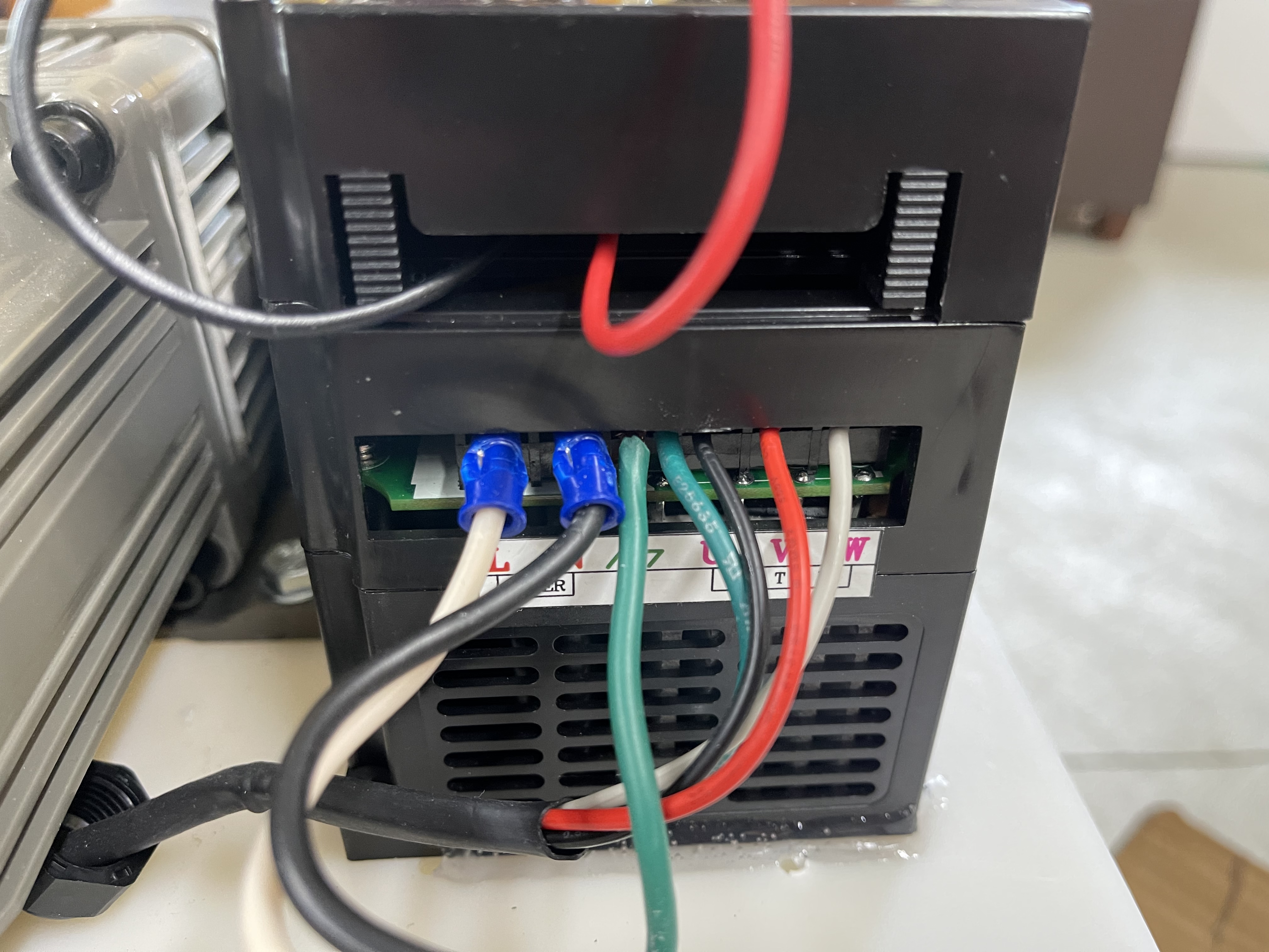
L is the black wire (hot)
N is the white wire (neutral)
For the motor wiring, you want Black red and white. U is black, V is red and M is white. Look at the pictures I posted earlier which show the actual connections. The ground wire for the power input AND the motor ground should both be connected to ground on the module.
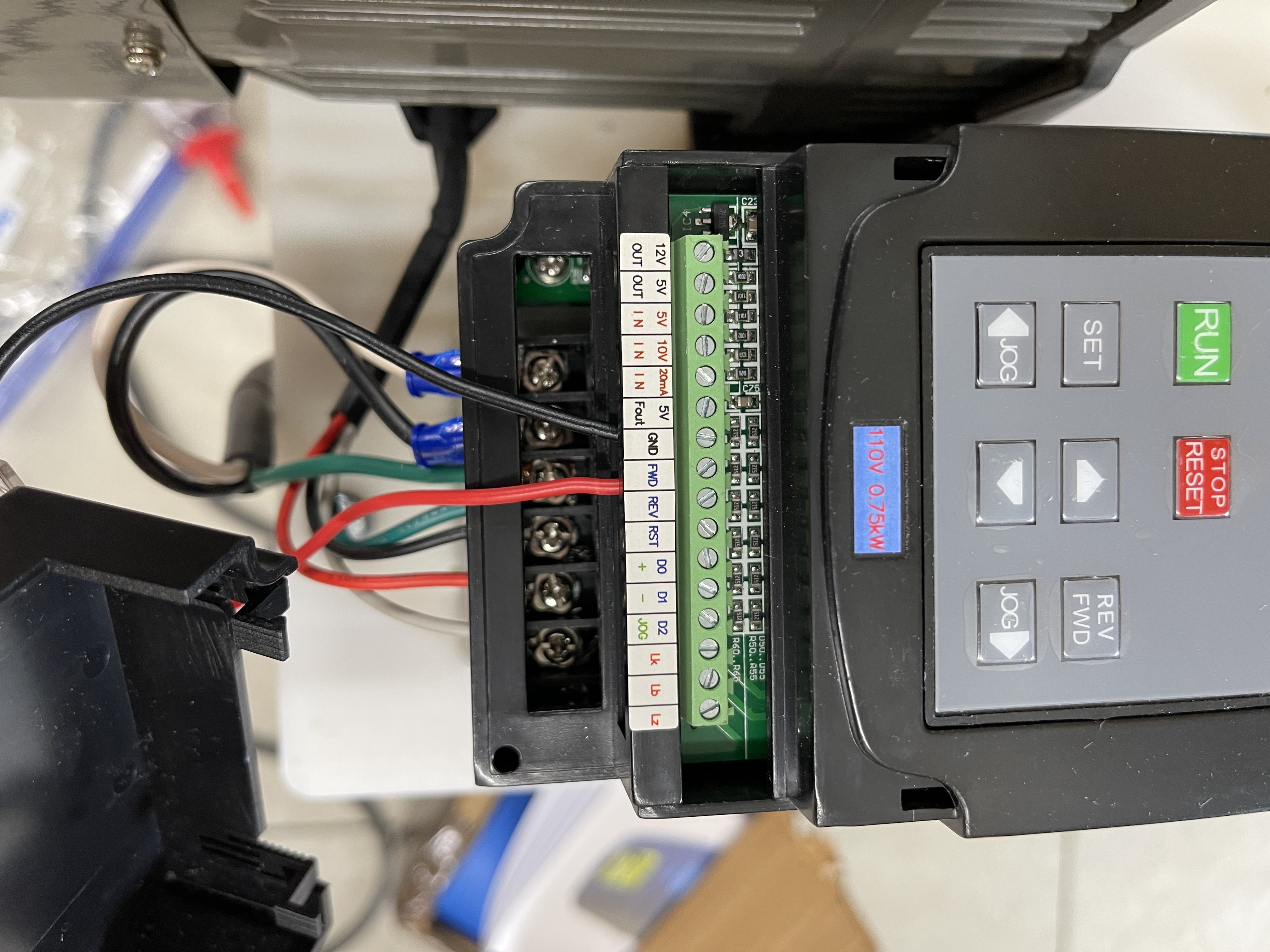
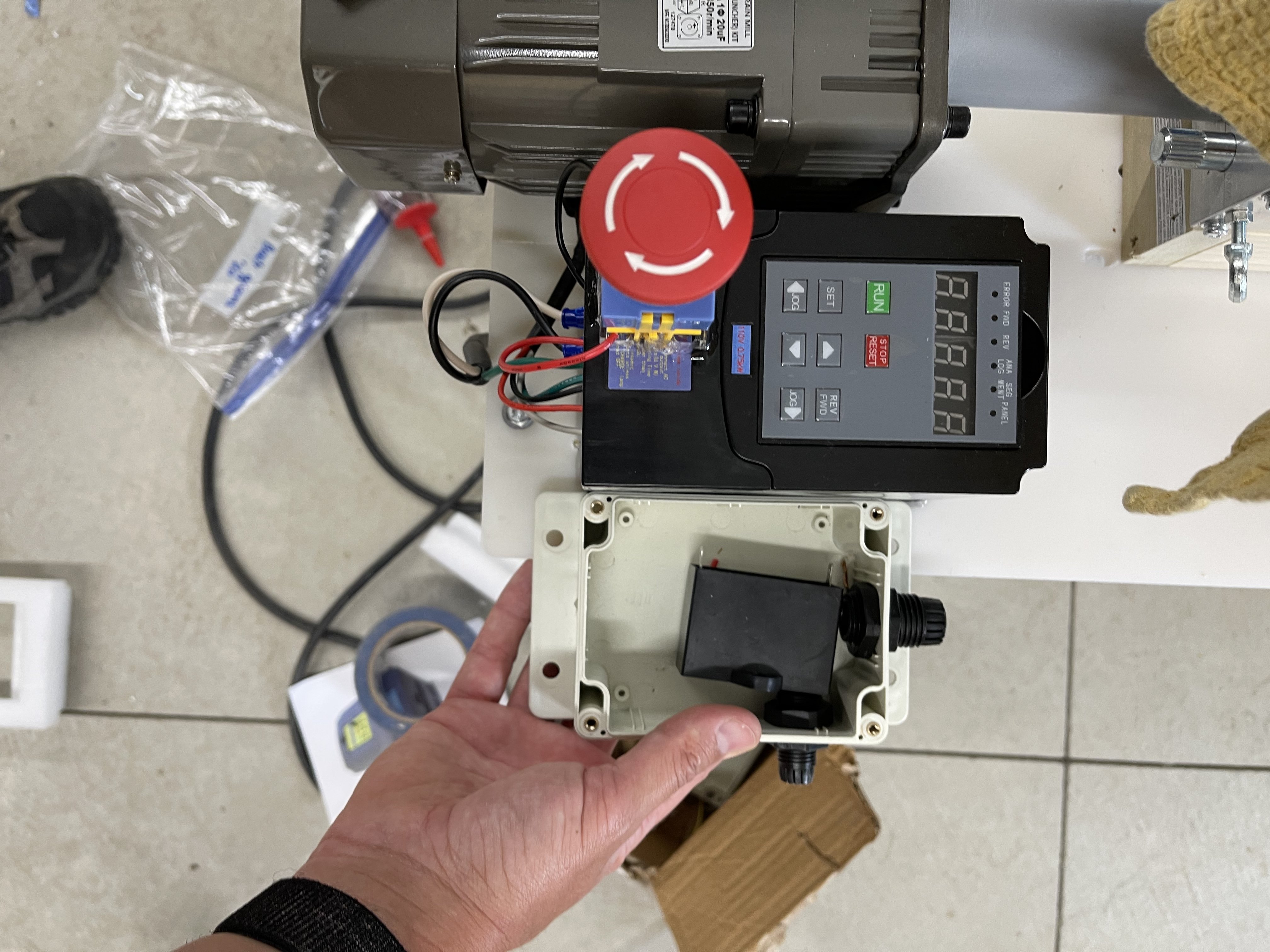
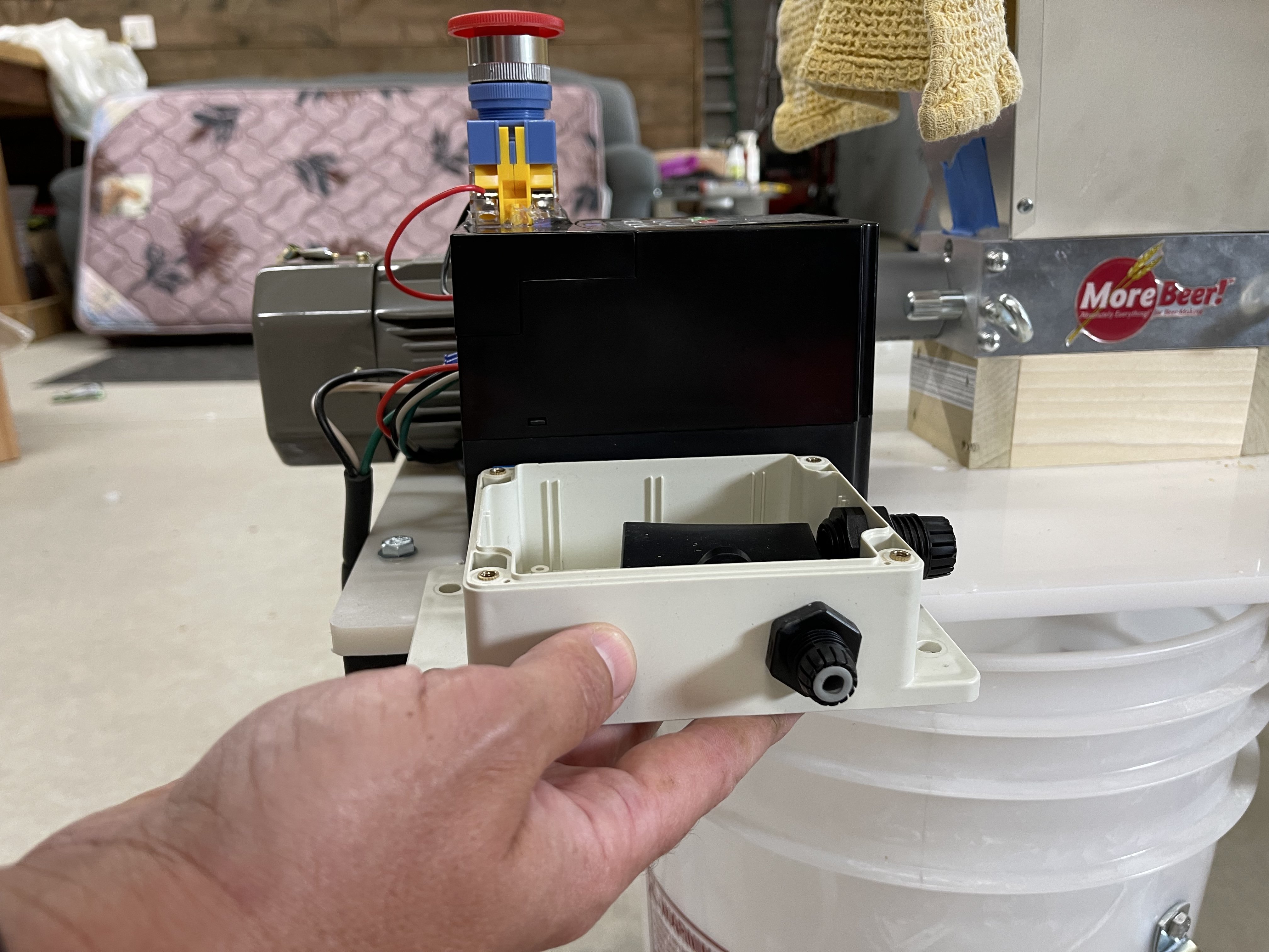
Again, I would HIGHLY recommend looking at my pictures posted earlier and installing the on/off switch that Morebeer provided as a safety switch. Using one side of the switch (because if you look at it, it has disconnects on both sides) and use any two wires to connect to the switch with one lead going into FWD and one going into GND. Then, in the setup screen, I believe it’s option 4 or 5, you want to control the operating using the external switch rather than the push button on the controller itself. Apologies in advance as I still need to make a video stepping people through the options. If anyone else has already configured the system, feel free to post the video and save me a step.
")


![Craft A Brew - Safale S-04 Dry Yeast - Fermentis - English Ale Dry Yeast - For English and American Ales and Hard Apple Ciders - Ingredients for Home Brewing - Beer Making Supplies - [1 Pack]](https://m.media-amazon.com/images/I/41fVGNh6JfL._SL500_.jpg)


