• Please visit and share your knowledge at our sister communities:
  • If you have not, please join our official Homebrewing Facebook Group!

    Homebrewing Facebook Group

iSpindle - DIY Electronic Hydrometer

Homebrew Talk

Help Support Homebrew Talk:

This site may earn a commission from merchant affiliate links, including eBay, Amazon, and others.
@Thorrak : Apologies for not being clear in my original post. By "config", I was referring to the iSpindel setup, where you pull the PCB out and initiate the configuration mode by hitting the ESP8266 reset button a couple of times, assuming you had the PCB in the petling.

None of what I'm working through is at all an issue with Fermentrack. Fermentrack was only mentioned because it'd worked well for iSpindel calibration before, and was handy when I was trying to figure this out.
 
@Thorrak , I believe he is talking about putting the iSpindel into configuration mode to enter the calibration polynomial. But, I believe that both ubidots and Fermentrack disregard this when doing there own calibration, since they rely on the "tilt" variable. I could be mistaken, but in Ubidots, I have to enter the polynomial to create S.G. data.

And as I mentioned, I have to take the cap off to charge which always messes with the calibration anyhow.

Precision instruments, they are not.
OH. Yes, exactly. You don’t need to enter the calibration polynomial into the iSpindel - Fermentrack handles it all on its own.
 
New to the forum, so be gentle lol. I bought parts in order to build 5 iSpindels (PCB 4.0) using @Open Source Distilling videos as reference. Awesome job by the way!!! I had to wait a couple months for everything to arrive. Finally built one and had issues with being able to flash the firmware. Built the 2nd and it actually worked out well, but haven't fully calibrated it yet because I wanted to build the rest so I could do them all at once. Built the next 3 last night and similar to the 2nd one that worked had issues with it being too tight to fit in the Petling, so I tried shaving them down with the Dremel. I can't get any of the 3 to get into setup mode in order to connect them to WiFi. Not sure what went wrong, maybe shaved to much and screwed up some circuitry? Maybe solder joints aren't good enough? I saw someone comment that they re touched their solder joints and things started working. Not sure where to go from here. I am new to soldering so maybe i just suck at that lol. I wonder if the batteries and/or battery holders I got are too bulky which results in them being difficult to fit in the Petling...
 
Are you sure they were programmed properly previously? Were you able to put the device into AP mode successfully before the trim job? If so, I could see how a dremel might effect some solder joints.

Is the device getting power? Does the program LED flash when you press the reset button? If so, what does it do?
 
I made the mistake of not testing each one before i tried to shave them down to fit. Such a bonehead move on my part.

Here's a breakdown of each device...

iSpindel #01 - Works great!
iSpindel #02 - Flashes firmware OK; D1 Mini LED lights up when powered on, but not in the same way as #01. Flashes but won't stay flashing to get into config mode
iSpindel #03 - This was the original. Won't flash firmware, recognizes COM3 in flasher but won't flash. Log says begin find ESP8266 but doesn't proceed from there. No LED's light up at all (I removed LED from gyro on this one)
iSpindel #04 - Won't connect to flash firmware; LED on gyro lights up and stays on; LED on D1 Mini Does not light up.
iSpindel #05 - Flashes firmware OK with LED flashing; No LED on D1 Mini or gyro when powered on except gyro flashes briefly when powered on and off.

Obviously each one has different issues.
 
Hi, have an ispendel built and have some questions about setup and Ubidots. I've done some of the basic calibrations tasks. I have balanced it to 25.7 degrees, and have placed it on a level surface and calibrated it. With sugar and water i have taken a few measurements as follows

25.73 @ 01.00 sg
46.63 @ 01.045 sg
61.12 @ 01.065 sg
70.02 @ 01.080 sg

Using the spreadsheet provided in the ispendel website (Calibration) I get this result
-0.050364959*tilt^2 + 6.868698667*tilt - 185.8498673

My understanding was that I needed to connect to the iSpindel directly via wifi, goto configuration page and insert that number in the polynomial box.
Is this all correct?

I have muddled thru setting up ubidots stem, and I get readings. After placing the number into the iSpendel, and placing the iSpendel back into 1.080SG sugar water I get a tiilt reading of 69.08, and a gravity reading of 48.3. I dont understand what the 48.3 is telling me as I was expecting something more like a specific gravity number. The tilts is also a touch off probably from pulling it out and putting it back in the plastic bottle to connect to it. From the ispendel documentation they talk about plugging this number into A "derived variable" inside Ubidots, not into the ispendel. My issue here is that the STEM version of Ubidots doesnt look like it has the ability to do a Derived Variable.. So if i have that wrong let me know, or perhaps a point to another option to track other than ubidots.
 
I was asking about the effect of pulling the circuit board out of the petling on the accuracy of readings a couple days ago. After reading the issues section of the iSpindel GitHub, someone in a calibration post had a simple suggestion for dealing with the issue: take a screwdriver or other small conductive implement, and short the reset pins. I tried it, and voila! Kicks the iSpindel into configuration mode without having to remove it.

Now, I figure there's a reason that "short" and electronics aren't positively related. But if you set up configuration mode when you initially slide the PCB into the petling, get the polynomial equation out of the spreadsheet, short it once to enter into configuration, enter the polynomial equation and set it to wherever you're pushing the data to, I doubt that'd be a long-term issue, and you wouldn't have to pull the PCB out after calibration.

Yes, you can use anything metal on the reset pins. I usually just grab a regular old pen :) Or forceps, or screwdriver, or butter knife, or whatever!

This is useful to reset the iSpindel and also to put it into configuration mode as you don't want to disturb the internal components after calibration unless absolutely necessary.
 
I made the mistake of not testing each one before i tried to shave them down to fit. Such a bonehead move on my part.

Here's a breakdown of each device...

iSpindel #01 - Works great!
iSpindel #02 - Flashes firmware OK; D1 Mini LED lights up when powered on, but not in the same way as #01. Flashes but won't stay flashing to get into config mode
iSpindel #03 - This was the original. Won't flash firmware, recognizes COM3 in flasher but won't flash. Log says begin find ESP8266 but doesn't proceed from there. No LED's light up at all (I removed LED from gyro on this one)
iSpindel #04 - Won't connect to flash firmware; LED on gyro lights up and stays on; LED on D1 Mini Does not light up.
iSpindel #05 - Flashes firmware OK with LED flashing; No LED on D1 Mini or gyro when powered on except gyro flashes briefly when powered on and off.

Obviously each one has different issues.

Hey Javajoe,

Thanks for your kind words.

Are you able to hook up the D1 mini to a serial monitor via USB cable? It should offer some insight into what's going on. I think I'll do a video on how to do this in the future.
 
I made the mistake of not testing each one before i tried to shave them down to fit. Such a bonehead move on my part.

Here's a breakdown of each device...

iSpindel #01 - Works great!
iSpindel #02 - Flashes firmware OK; D1 Mini LED lights up when powered on, but not in the same way as #01. Flashes but won't stay flashing to get into config mode
iSpindel #03 - This was the original. Won't flash firmware, recognizes COM3 in flasher but won't flash. Log says begin find ESP8266 but doesn't proceed from there. No LED's light up at all (I removed LED from gyro on this one)
iSpindel #04 - Won't connect to flash firmware; LED on gyro lights up and stays on; LED on D1 Mini Does not light up.
iSpindel #05 - Flashes firmware OK with LED flashing; No LED on D1 Mini or gyro when powered on except gyro flashes briefly when powered on and off.

Obviously each one has different issues.

You've got nothing to lose by touching up the solder joints now. This is also why I don't recommend removing the gyro LED, my battery life is more than adequate with it remaining.

I would try using my method of clearing the memory addresses and re-programming #02. I posted a video of what mine was doing to give me problems.

If touching up the solder joints earns you any success, try clearing and reprogramming the others. I'm afraid that's all the help I can offer at this point.
 
I dont understand either of these Gravity readings.

Water: Tap water
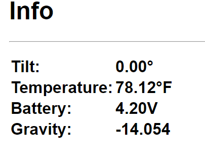
Polynomial: -0.00031*tilt^2+0.557*tilt-14.054 - this is the example given on the page
Tilt: 24.96 degrees
Temp: 70.59 F
Batt: 3.97v
Gravity: -0.402


Water: Tap water
Polynomial: -0.050364959*tilt^2 + 6.868698667*tilt - 185.8498673 - created via excel sheet
Tilt: 24.93 degrees
Temp: 70.59 F
Batt: 3.97v
Gravity: -46.002

Should the reading be 0 or somewhere close to it? or maybe even 1 as in 1.00 SG??
What should I be seeing here if it where correctly operating?
Is this a Plato number or an SG number?
 
Ok, so it seems (what i didnt know) that the readings are in PLATO, that accounts from some trouble understanding the numbers. As far as the polynomial, i cannot seem to find a calculator that will spit out a number that actually works. I've tried like 3, saved them to the ispendel, and the gravity reading are 0, so something is wrong with the polynomial. GOing back to the stock polynomial seems to work fine now at 1.00sg, but its wrong in 1.080 sg. Reads 1.097. I think I am going to bail on Ubidots and use Brewfather, and i believe they have a calibration process that should account for this issue. I hope ;)
 
I made the mistake of not testing each one before i tried to shave them down to fit. Such a bonehead move on my part.

Here's a breakdown of each device...

iSpindel #01 - Works great!
iSpindel #02 - Flashes firmware OK; D1 Mini LED lights up when powered on, but not in the same way as #01. Flashes but won't stay flashing to get into config mode
iSpindel #03 - This was the original. Won't flash firmware, recognizes COM3 in flasher but won't flash. Log says begin find ESP8266 but doesn't proceed from there. No LED's light up at all (I removed LED from gyro on this one)
iSpindel #04 - Won't connect to flash firmware; LED on gyro lights up and stays on; LED on D1 Mini Does not light up.
iSpindel #05 - Flashes firmware OK with LED flashing; No LED on D1 Mini or gyro when powered on except gyro flashes briefly when powered on and off.

Obviously each one has different issues.
I had major issues with my setup for my iSpindel at the start. The issue was I didnt clean off the PCBs before soldering them, and had a few cold joints despite it looking perfect. At one point just pressing the iSpindel into the tube would cause it to reset, so retouching them is certainly a good place to start.
 
Hey Javajoe,

Thanks for your kind words.

Are you able to hook up the D1 mini to a serial monitor via USB cable? It should offer some insight into what's going on. I think I'll do a video on how to do this in the future.

Thanks! Never done this before, lol, but I attached the log I got after booting it up (deleted a bunch of stuff since it says there is a lot of info lol). Looks like there are a few issues. Bad temp sensor or bad solder joints. I'm going to go through and try and clean up the solder and will report back. Thanks again!
 

Attachments

  • iSpindel_02-log.txt
    557 bytes
Last edited:
@Open Source Distilling @gromitdj - Update - I went through and tried to clean up some solder joints and I got #2 & #4 to connect in config mode, however, both seem to get stuck in calibration. Both give errors "Acc Test Connection ERROR" and if I go to calibrate i get ""MPU6050 connection failed"
I have heard that the gyro are hit and miss, are they bad or is it something else?
also, not getting any tilt information
1590218125582.png
 
Last edited:
@Open Source Distilling @gromitdj - Update - I went through and tried to clean up some solder joints and I got #2 & #4 to connect in config mode, however, both seem to get stuck in calibration. Both give errors "Acc Test Connection ERROR" and if I go to calibrate i get ""MPU6050 connection failed"
I have heard that the gyro are hit and miss, are they bad or is it something else?
also, not getting any tilt information
View attachment 681694

It looks like your issue is similar to the one in the link below. Yeah, sounds like a bad gyro somehow.
https://github.com/universam1/iSpindel/issues/345
 
It looks like your issue is similar to the one in the link below. Yeah, sounds like a bad gyro somehow.
https://github.com/universam1/iSpindel/issues/345

Got it! I will try and swap out the gyros from the other 2 devices that aren't improving. #3 I think is fried and still having issues with #5 🤷‍♂️. 3/5 of the units are promising (1 working). If it is the gyro on both units, it sucks that 2/5 I bought are bad,but I have read that seems to be the case.
 
Hi All, new to the forum and...

Not quite finished yet, but I have built and got working an Ispindel, on a V4 PCB. I am still waiting for a switch and a higher capacity battery, before I call it finished, but working it is. I have opened a STEM account with Ubidots, which I have (rather badly) got to display my data. I see that 'widgets' can be shared and I have seen a few good ones on here and wonder if anyone would be willing to share some of the better ones please?

I am particularly looking for one which combines SG with temperature and one with signal and battery voltage, but any others welcome please.
 
I see that 'widgets' can be shared and I have seen a few good ones on here and wonder if anyone would be willing to share some of the better ones please?
Yeah, I would be interested in seeing this as well. Anyone willing to share their Ubidots widget setup?
 
Ballast for iSpindel
Hi All,
I'm really struggling with the 4.0 pcb to get it to float at 25 degrees - it's no where near it. I've read a couple of posts about adding weights but I haven't got space in the tube to add enough. I have a larger pet tube so may have to resort to adding enough and somehow wedge the pcb in there too
Any tips would be gratefully received
Many thanks
 
I wonder if anyone has done any stability tests on the iSpindel tilt data?

Today I ran a test, to see how much the tilt value changed with no actual change in the SG of the fluid - tap water.
My little experiment began with a reported tilt of 19.77 deg and ended some 13 hours later with it reading 22.34 deg - a 2.64 difference. The graph showed a steady drift in the degree reading.

During that period the initial temperature was 18.18C and ended at 18.69C, again a gradual change in temperature.

It does seem rather an extreme change in tilt value, for such a tiny variation in temperature. What does the panel think?
 
Ballast for iSpindel
Hi All,
I'm really struggling with the 4.0 pcb to get it to float at 25 degrees - it's no where near it. I've read a couple of posts about adding weights but I haven't got space in the tube to add enough. I have a larger pet tube so may have to resort to adding enough and somehow wedge the pcb in there too
Any tips would be gratefully received
Many thanks

Same pcb here, in a PET big XL. I assume you have done the 90 deg calibration, with the PET perfectly horizontal?

I soldered my battery in, rather than use a holder and proceeded to try to get it to 25 deg. It floated only slightly down from horizontal at the bottom. To get an idea of the amount of extra weight needed to get it to 25 deg., I wrapped 4mm plumbers lead around the outside of the PET at the bottom. It seemed I needed around 20g or 2 x 2" lengths. I moved the battery down as far as possible, then stuck a strip of that spongy double sided tape to the pcb, either side of the battery, then the lead onto that. That had it floating at 16 deg and I was able to snip off lead from the upper ends, 4mm at a time, until I hit 24 deg at 20C. I think my final weighting was 16g of lead.

I see you said a larger PET. The larger the PET, the greater the displacement, the more the weight needed to get the correct 25 deg.. The lower you can get the weight in the PET, the less weight will be needed.
 
Thanks Harry.
I did the 90 deg calibration first with no problem. I was then shocked when it bobbed around on the surface with barely anything submerged at all! I've got some fishing weights that are around 25g. I'll try them on the outside first to see if it has the desired effect - I may opt for removing the battery holder as you suggested to see what difference that makes.
Thanks for your help
Alastair
 
Has anyone had success using a coaxial cable to get an iSpindel signal out of a stainless steel fermenter? There's a description of it here in this German homebrewer forum: Google Translate

I've seen a couple posts mention it, but no one else reporting results of trying it.
 
I may opt for removing the battery holder as you suggested to see what difference that makes.
Thanks for your help
Alastair

My reasons for not using the battery holder were that I had ordered one and I thought it would be handy to be able to adjust the position of the battery to fine tune to the 25 deg.
 
Does anyone happen to have a single PCB they'd be willing to sell me? I don't need 5/10 from PCBWay. Something fritzed out with my D1, and in the process of trying to desolder the D1 to remove it and put a new one on, I managed to burn through the soldering cup and expose some of the internal wire. Woops!


I have a couple of spare Jeffrey 2.1's if you need them. Just working on it myself. I can'y get any of the D1 minis to connect in AP mode after flashing. Did you get past this issue.
 
Back
Top