OhioEd,
Thanks for this amazing thread!! Thanks to all who have contributed.
I am in the process of purchasing components for my E-Brewery. I am using 5500 watts in the BK, 5500 watts in the HLT, and 1500 watts in the RIMS all elements are 240vac to keep me on a 40 amp circuit. I have a few questions.
1) Will a 3 pole 10amp 120vac Ice cube relay work instead of the 2 Pole for the E-stop?
Sure, just leave the 3rd pole empty. Here is the Relay and Socket I used:
http://www.automationdirect.com/adc.../5A_Electro-Mechanical_Cube_Relays/QM2N1-A120
http://www.automationdirect.com/adc...-_Timers/Relay_Sockets_-a-_Accessories/SQM08D
2) What contactors does the 2 position selector switch need? 1NO & 1NC?
Yes, 1 NO and 1 NC
3) What curve breakers are you using? B for the elements and D for the rest?
Actually, I bought based on what was on-hand at the time I ordered which was are all C Curve except the 30amp double poles which are B Curve. They all came from AutomationDirect.
4) Would a 1 amp breaker work for F9?
F9 is intended to protect the BCS. The max current on the +5vdc is 300mA, so really the fuse should be less than 300mA. I ended up with a .5a breaker, because it was what I could find...not 100% sure it would really save the BCS.
5) Do you have a link for your terminal blocks? Do they require jumpers, or do they direct contact each other and need to be terminated with end plates?
The terminal blocks came from Mouser.com. I used a variety of sizes. They do require a jumper bar if you need to connect them. The jumpers come in various sizes, you "can" buy longer ones and cut them down as needed if you don't know exactly what you need.
I downloaded a PDF of the Manufacturers Terminal blocks & accessories and hunted down the sizes and pieces I needed.
Here is a link to one of the terminal blocks...
http://www.mouser.com/Search/ProductDetail.aspx?R=CTS10Uvirtualkey56110000virtualkey845-CTS10U
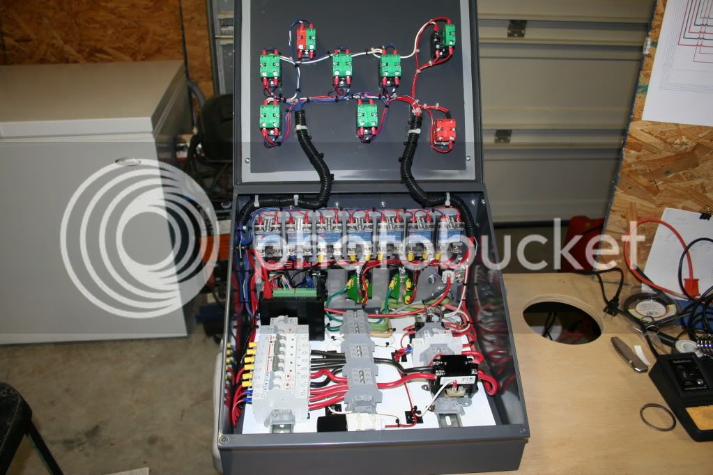
6) What size enclosure should I look for? 12"x12"x6" or 16"x12"x6"? I will be utilizing din rails, but I will have 8 ssr's due to my Rims Element being 240vac.
I think you could accommodate what I have in a 16"x12"x6" square box but size will depend on what devices you need to mount... There are no Timers, displays, or PID's on my panel so I actually had plenty of real estate on the front panel. The back with all the SSR's and connectors was quite tight. Also, the slant top on my box made mounting components close to the front challenging.
Thanks,

 I'm planning on doing a very similar build (BCS, etc) so finding your thread is a huge score for me.


![Craft A Brew - Safale BE-256 Yeast - Fermentis - Belgian Ale Dry Yeast - For Belgian & Strong Ales - Ingredients for Home Brewing - Beer Making Supplies - [3 Pack]](https://m.media-amazon.com/images/I/51bcKEwQmWL._SL500_.jpg)