• Please visit and share your knowledge at our sister communities:
  • If you have not, please join our official Homebrewing Facebook Group!

    Homebrewing Facebook Group

DYI fermentation chamber

Homebrew Talk

Help Support Homebrew Talk:

This site may earn a commission from merchant affiliate links, including eBay, Amazon, and others.

bruce_the_loon

Well-Known Member
Joined
Nov 21, 2015
Messages
1,517
Reaction score
1,672
Location
Port Elizabeth, South Africa
After a few years of brewing, I finally got around to start building my fermentation chamber. Now before anyone starts on using fridges etc for a chamber, in South Africa decent second-hand fridges are rare and new ones would have cost me about six times what I've spent on it.

I got hold of a working second-hand water cooler which turned out to have a mini-fridge as well. After much stripping of threads, swearing and tearing apart, I got the compressor unit and the full cooling circuit out intact. Powered it up and it chilled. Part one of the mission completed.
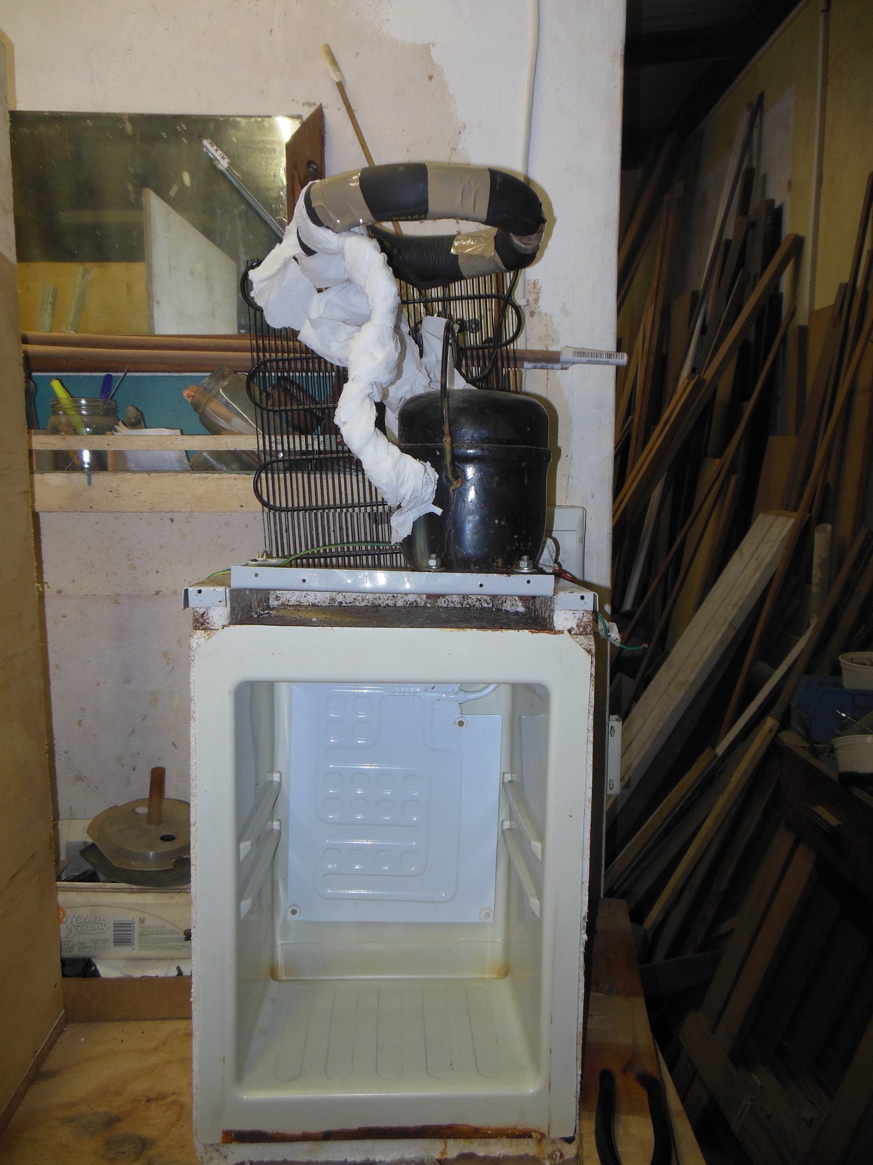
cooler_insides.jpg

Photo 1 - Compressor and cooling circuit extracted from the water cooler.
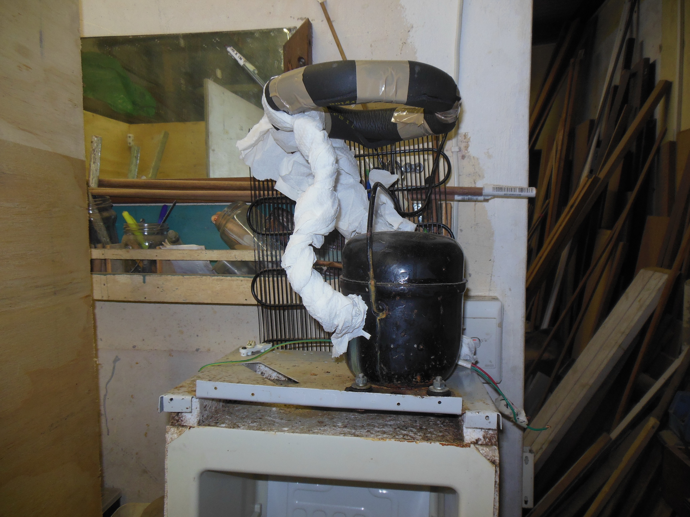
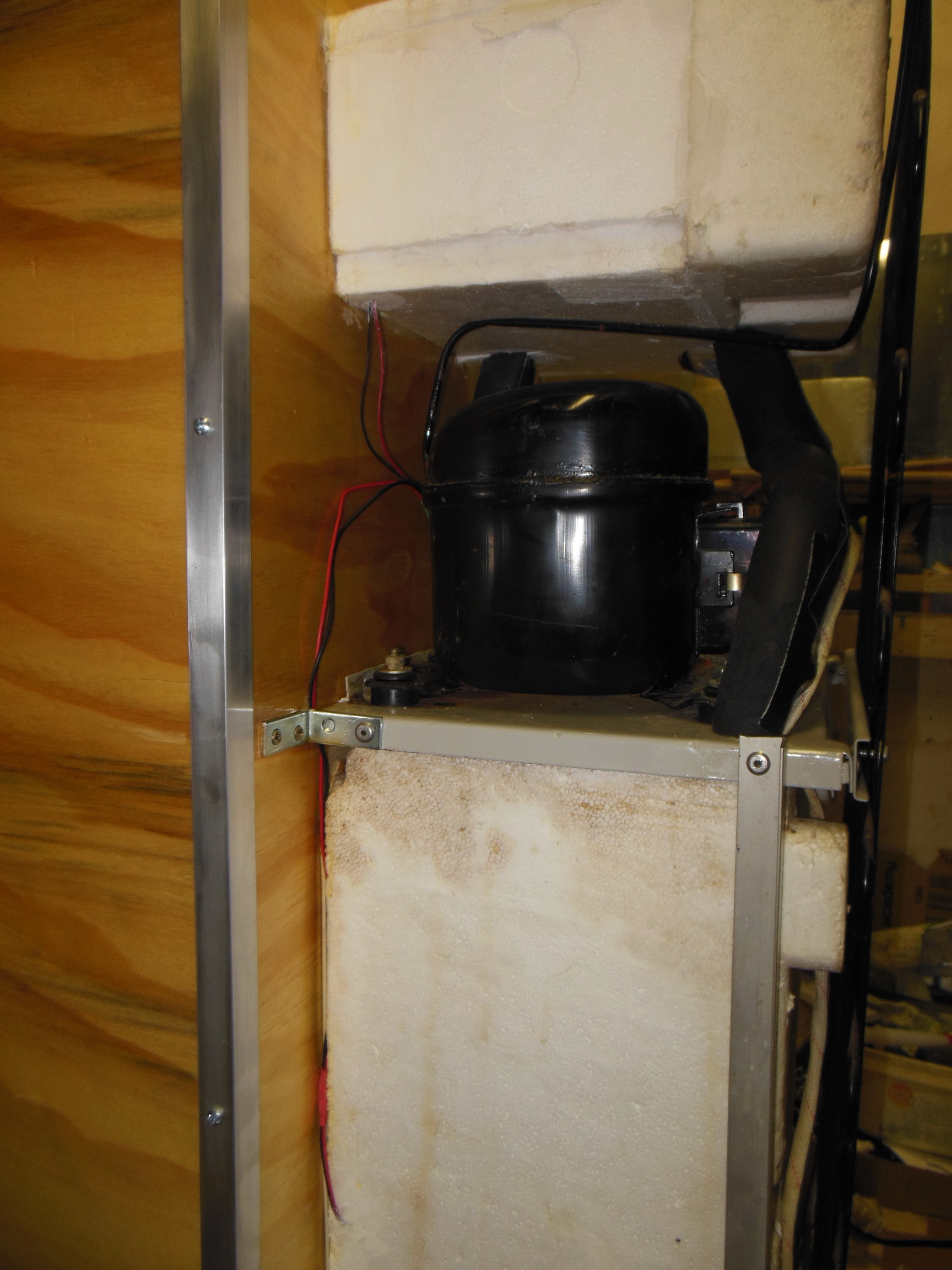
compressor_closeup.jpg

Photo 2 - Closeup of compressor and upper cooling circuit. Currently wrapped in foam insulation and paper towel for testing.

Next I rigged up the STC1000 controller to switch the compressor, wrapped the upper cooling circuit, which had been wound around the water bowl, in insulation and placed the temp probe from the controller into a container of water inside the mini-fridge and closed the door. Shifted the temps around a few times and the mini-fridge heat exchanger panel was able to handle temps down to 3°C.

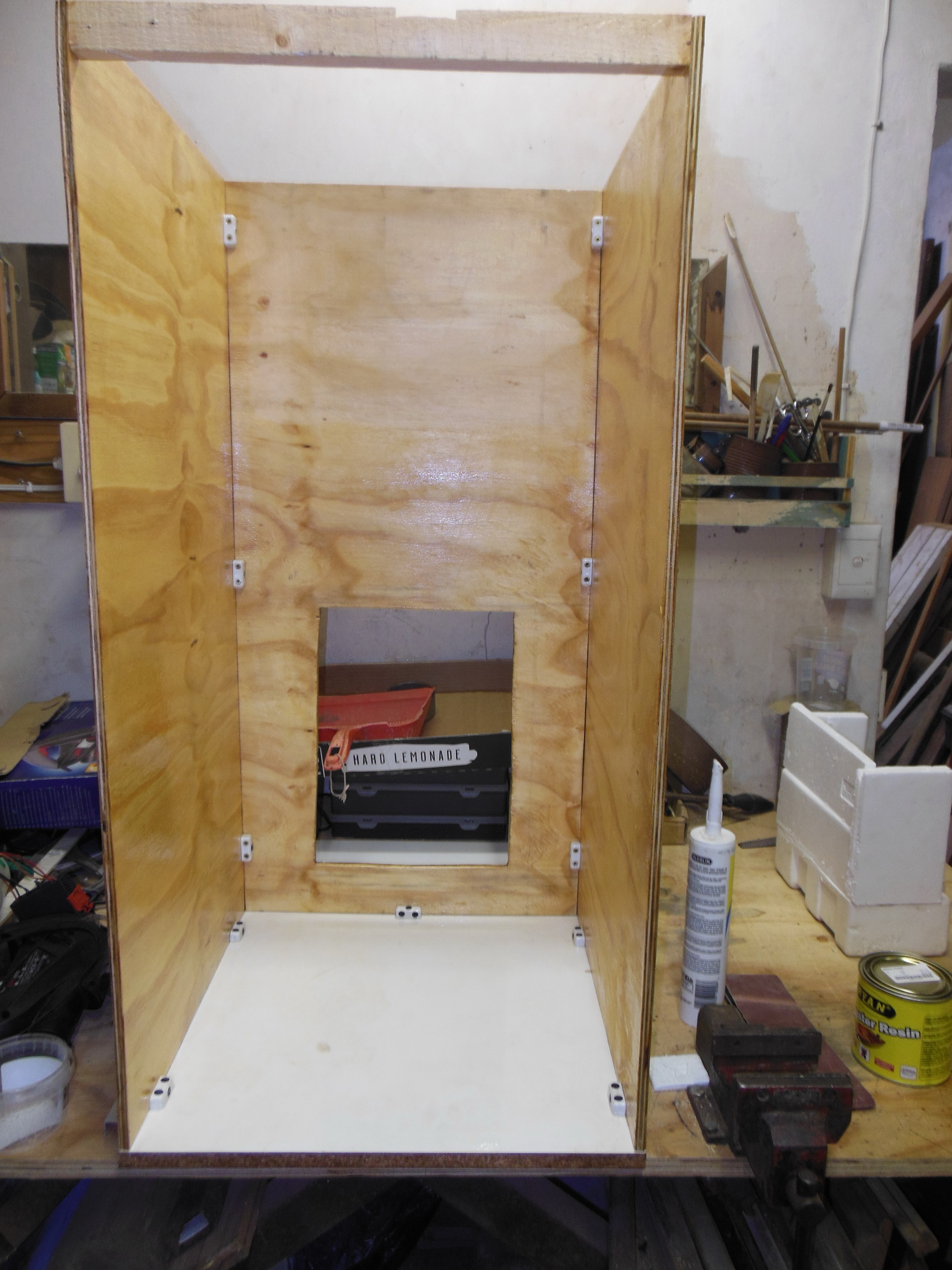
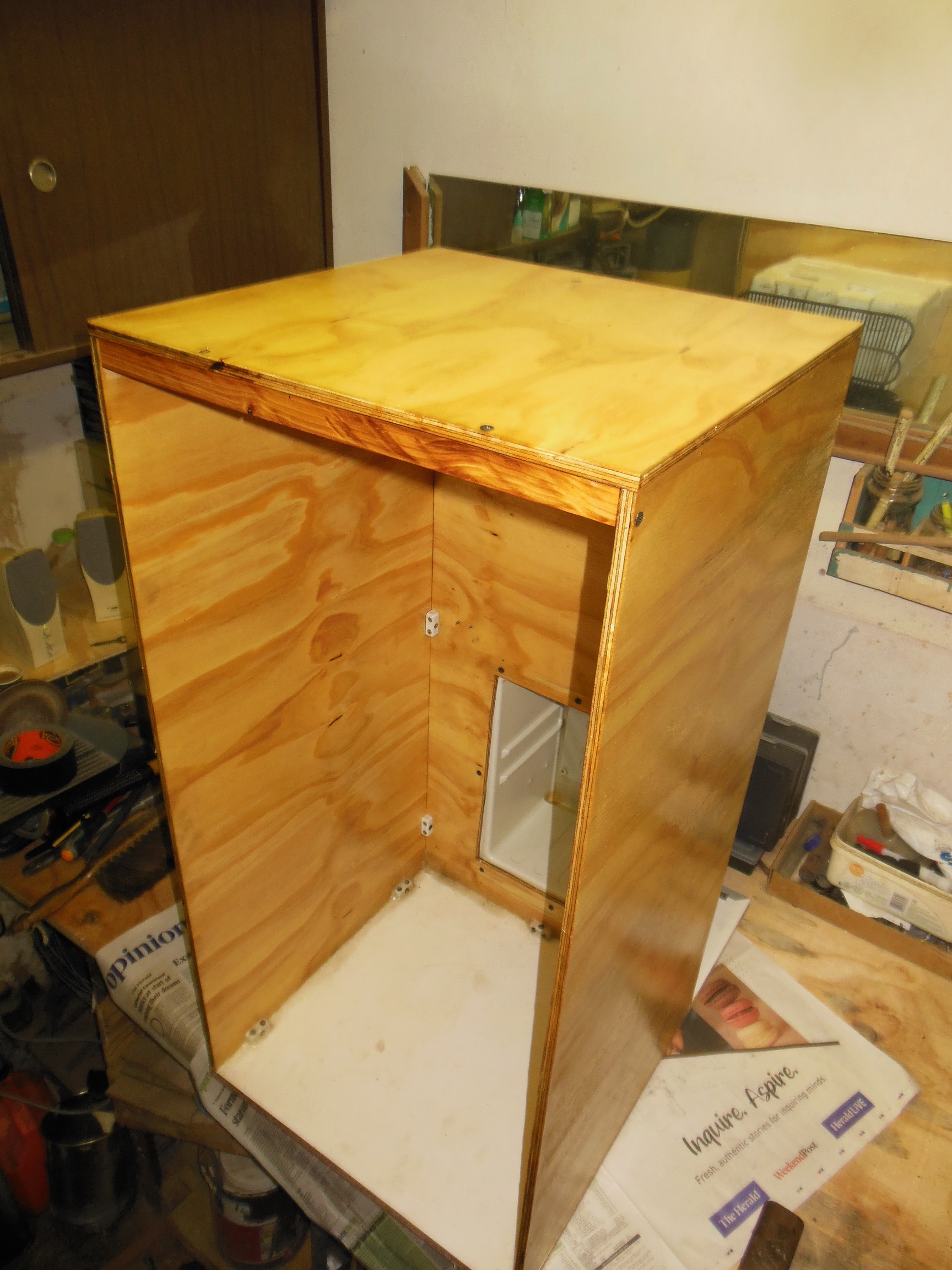
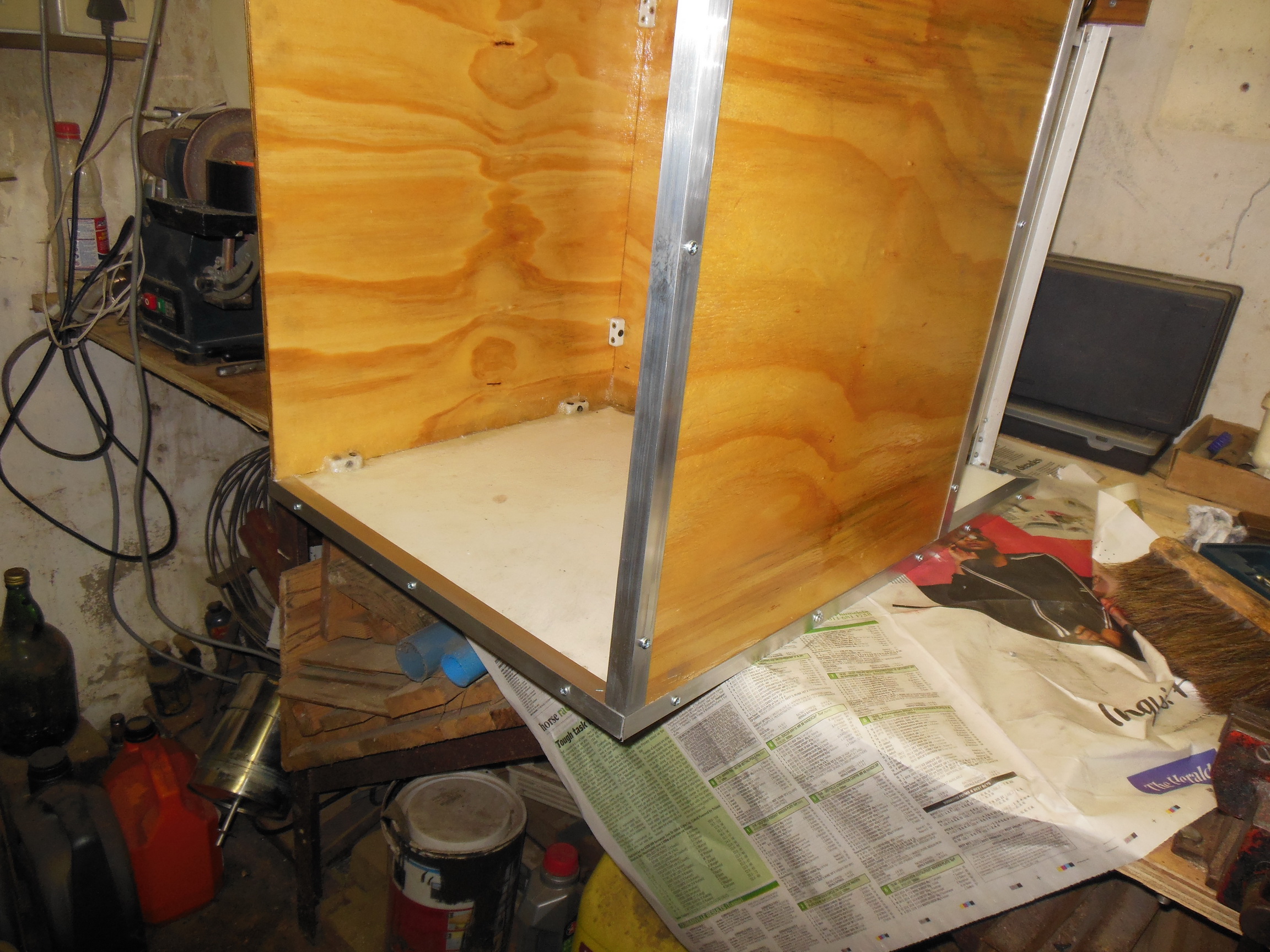
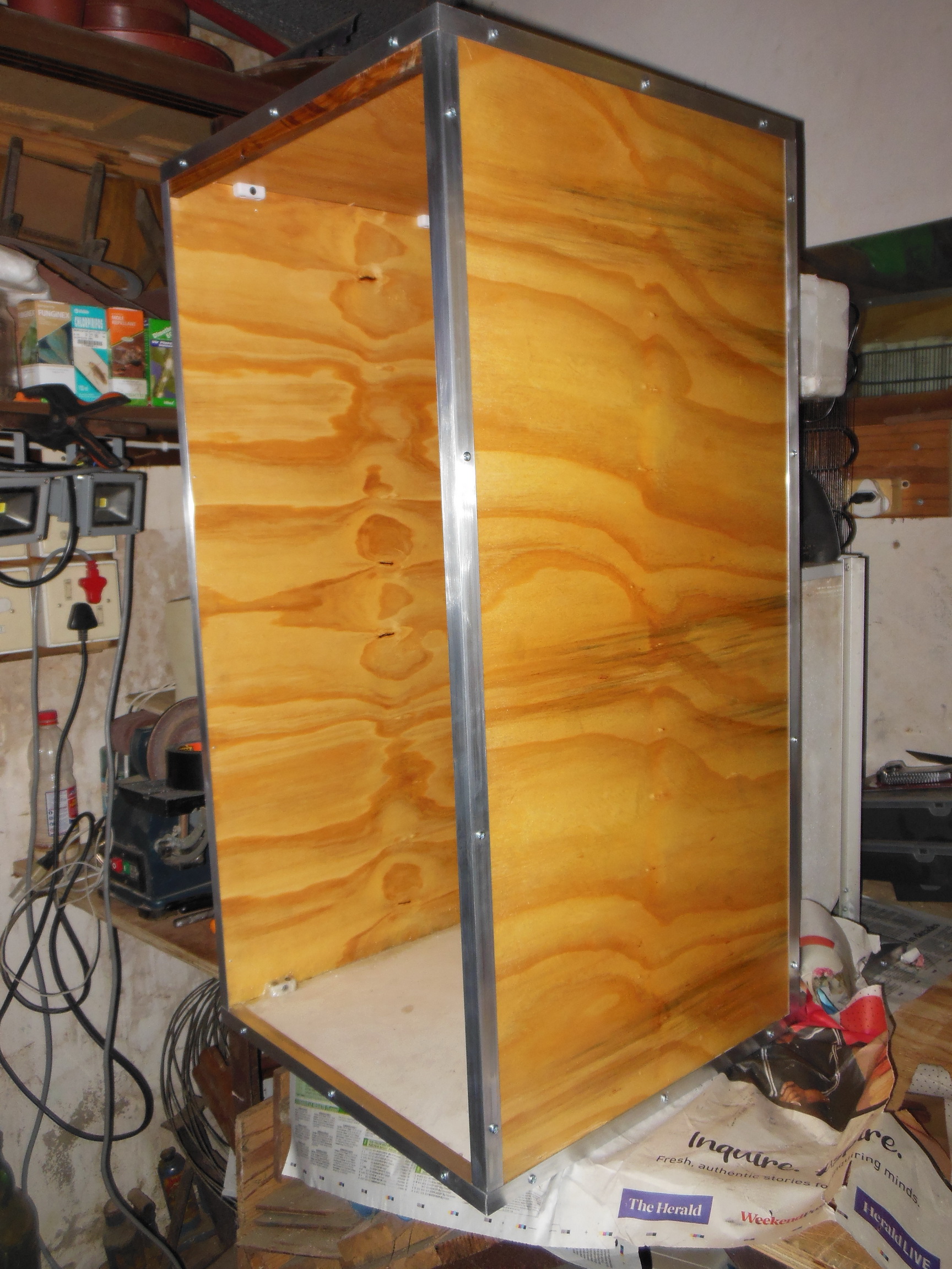
Started to build the chamber itself today. Cut some 10mm ply to size and mounted the sides and rear to the baseboard. Internal dimensions of the chamber are 45cm x 45cm x 90cm (18" x 18" x 36") which will have an effective size of 35cm x 35cm x 80cm (14" x 14" x 32") once the insulation has been fitted.

chamber_front_ported.jpg

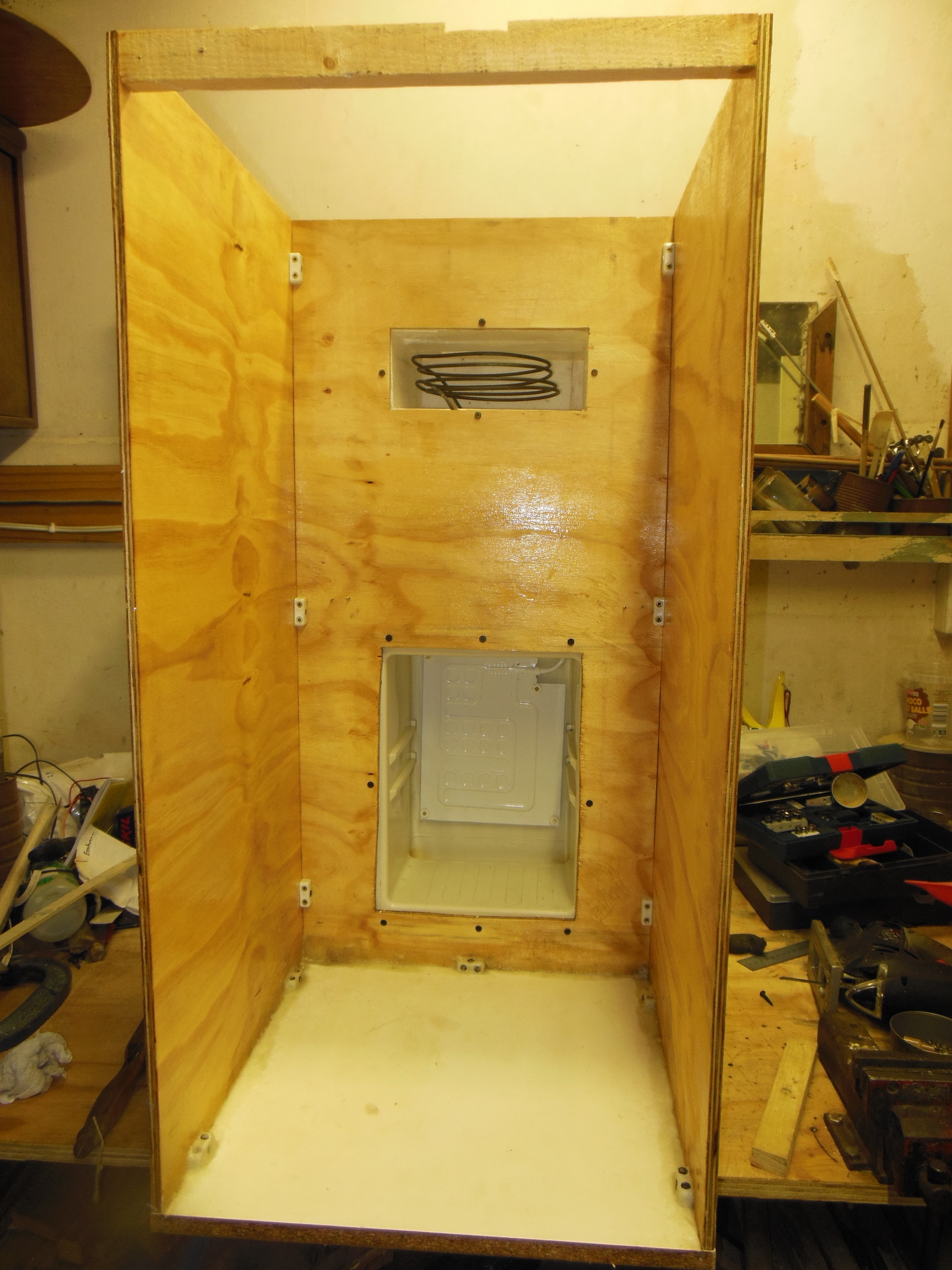
Photo 3 - Front view of the partially assembled chamber with the port for the mini-fridge chamber cut out.

Insulation is going to be 50mm Isotherm which is a polyester flexible blanket with an R of 0.79. I've used this around my fermenter before. If that doesn't work out, then 35mm polystyrene sheeting is the fallback plan.

chamber_rear_ported.jpg

Photo 4 - Rear view of the partially assembled chamber with the port for the mini-fridge chamber cut out.

The next step is to fabricate a chamber to enclose the chilling coils that had been wound around the water tank in the cooler. This chamber will be ported into the rear of the fermentation chamber like the mini-fridge chamber and fans will circulate air around both the chilling coils and the chiller plate. The STC1000 will be mounted above the chamber itself with the temperature probe inside the chamber to be secured to the fermenter (or even placed into a thermowell if I ever get around to it.)

chamber_front_with_fermenter.jpg

Photo 5 - Partially assembled chamber with my Mangrove Jack's 5g stainless steel fermenter.

Next few days will be spent on finishing the chamber construction, mounting the compressor and chiller circuits and figuring out which epoxy sealer to use to waterproof the inside of the chamber before insulating. Then there will be the electrics and the cursing and the testing. More pictures as the various stages are reached.

PS - All the rust on the compressor pipes is from the hot water heater plumbing in the water cooler (which had a hot water function as well) that decided to rust out.

Edit: changed photos to full size
 
Last edited:
Subscribed. Interested to see the finished result.
Sounds like you found a great solution!
 
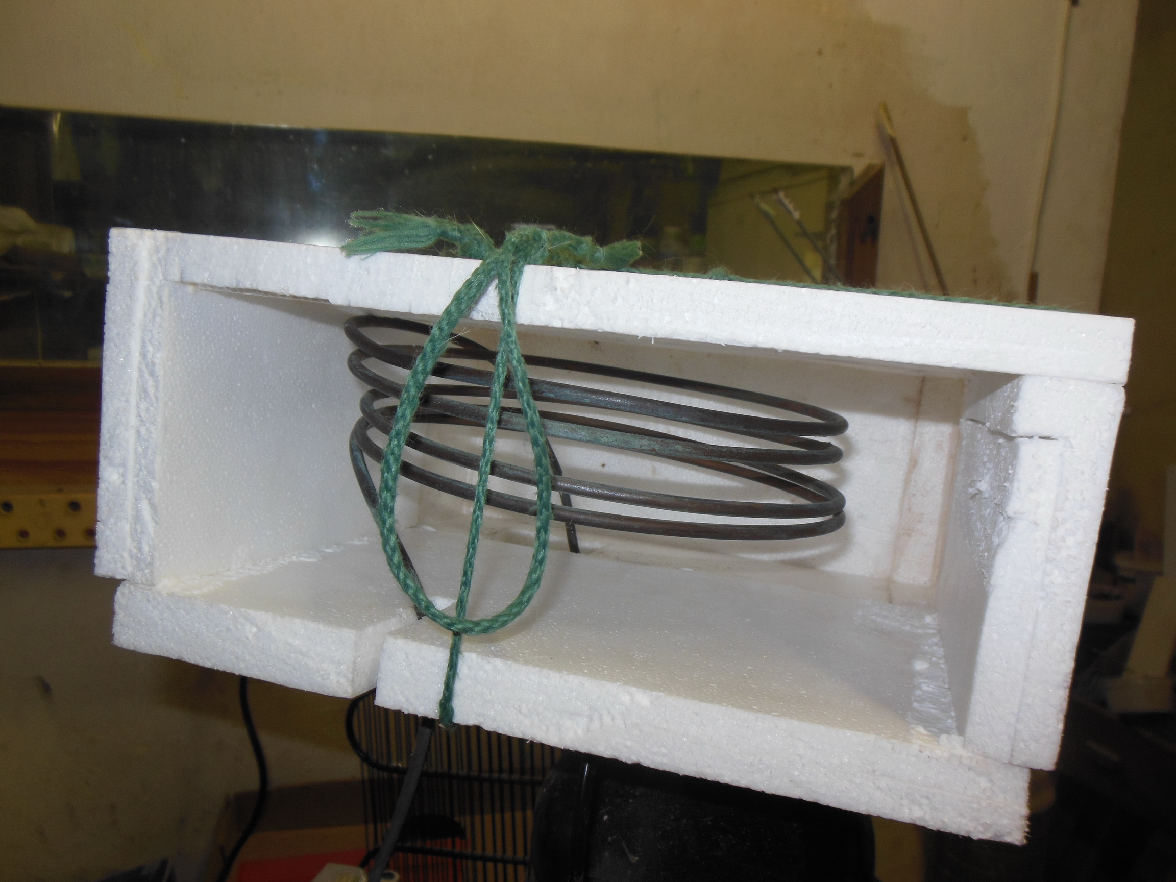
Not much visually accomplished this update. Adjusted the chamber width slightly to fix a bad math issue by taking 10mm off the width. Struggled to find a suitable plastic box to fit the upper chiller ring, gave up and decided to fabricate straight out of expanded polystyreme foam board. Which wasn't in stock at any of the hardware stores, so decided to recycle some of the monitor and computer packing material to fabricate the insulated box to duct the upper chiller into the chamber. Not the smoothest construction ever, but it will be hidden anyway.

upper_chiller_box.jpg

Photo 6 - Partially completed upper chiller coil housing assembled from recovered polystyrene.

One pipe from the coil will feed out through the slot visible in the short section and the other feeds through the bottom panel which has to be glued to the rest of the box once fitted in place.

Next step with the chamber is waterproofing as we have high humidity sometimes and condensation concerns abound. After discussions with a like-minded mob of technical, mechanical and tinkering experts, I settled on a couple of coats of polyester resin with fiberglass matting to seal the edges where the boards meet. First coat has been applied to the inside of the chamber except for where the port for the upper chiller needs to be cut.

chamber_polyester_resin_coat1.jpg

Photo 7 - First coat of polyester resin applied to the plywood and melamine surfaced boards for waterproofing. Shiny compared to the earlier photo.

Still to do today, maybe.
  • Apply rust converter to any surface rust spots on the compressor plate.
  • Design the mounting system for the compressor plate.
  • Find an artistically suitable case to mount the STC-1000 inside.
I've decided to edge the chamber with 19mm aluminium angle and face it with 19mm aluminium channel. Outer plywood surfaces, sides, door, roof and side panels for the compressor, will be varnished with clear yacht varnish.
 
This is cool..and I'm always amazed how straight some people can cut with hand tools. I sure as $!# can't. My FC is as crooked as a...<insert noun>

I think the only part of your post that I can relate to however is:

"After much stripping of threads, swearing and tearing apart," <-----I'm good at that stuff.

The main cuts on the plywood and the base were done on a table saw with guides, the port cut in the middle of the back was cut using a jigsaw and you can see the wandering lines there. There is trim going over that, so I don't care too much. If I had to do the long cuts with a handsaw, they would resemble a Norwegian coastline.

Amidst the stripping of threads is the memorable bolt into a nut welded to the frame, except the frame around the nut has rusted and now the nut spins freely inside a space only accessible when the bolt has been removed. That's when you worship the angle grinder.
 
Quick update for today, finished the upper chiller containment box and fitted it to the chiller coil on the refrigeration unit. Once the glue has dried overnight, the system will be positioned, the port in the rear panel cut out and the next layers of polyester resin applied. All during gaps between online meetings.

upper_chiller_box_installed_front.jpg

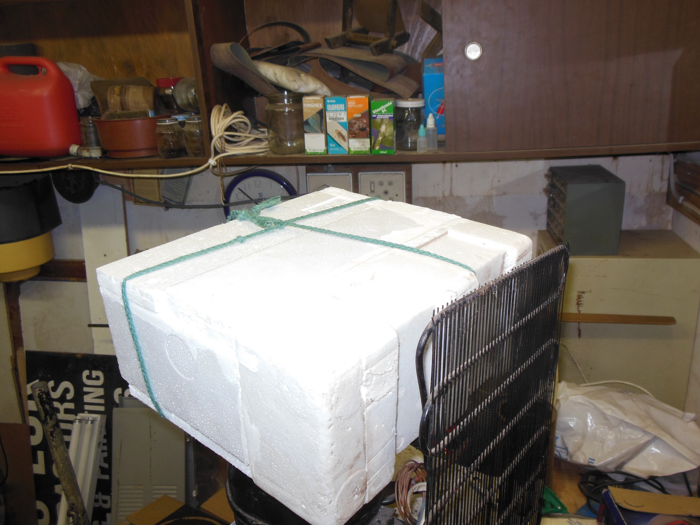
Photo 8 - Upper chiller box in place with string holding the bottom panel in place while the glue dries.

upper_chiller_box_installed_rear.jpg

Photo 9 - Upper chiller box from the back. Acrylic filler used to fill some holes and smooth out the divots in the previously-utilized EPS.

No More Nails works wonders on EPS, nice rigid bond after a couple of hours.

Once the glue has dried, one or two more side pieces of EPS need to go on to increase the thickness in a couple of places and a couple of lengths of foam refrigeration pipe insulation to insulate the exposed chiller pipes.
 
Big steps accomplished today. Got the compressor and chiller boxes mounted and tested at last.

Test fitted the compressor platform to get the resting position of the upper chiller box and jigsawed the port out of the rear panel.

chamber_rear_both_ports_cut.jpg

Photo 10 - Rear panel with both ports cut out and ready to start mounting the chiller assembly.

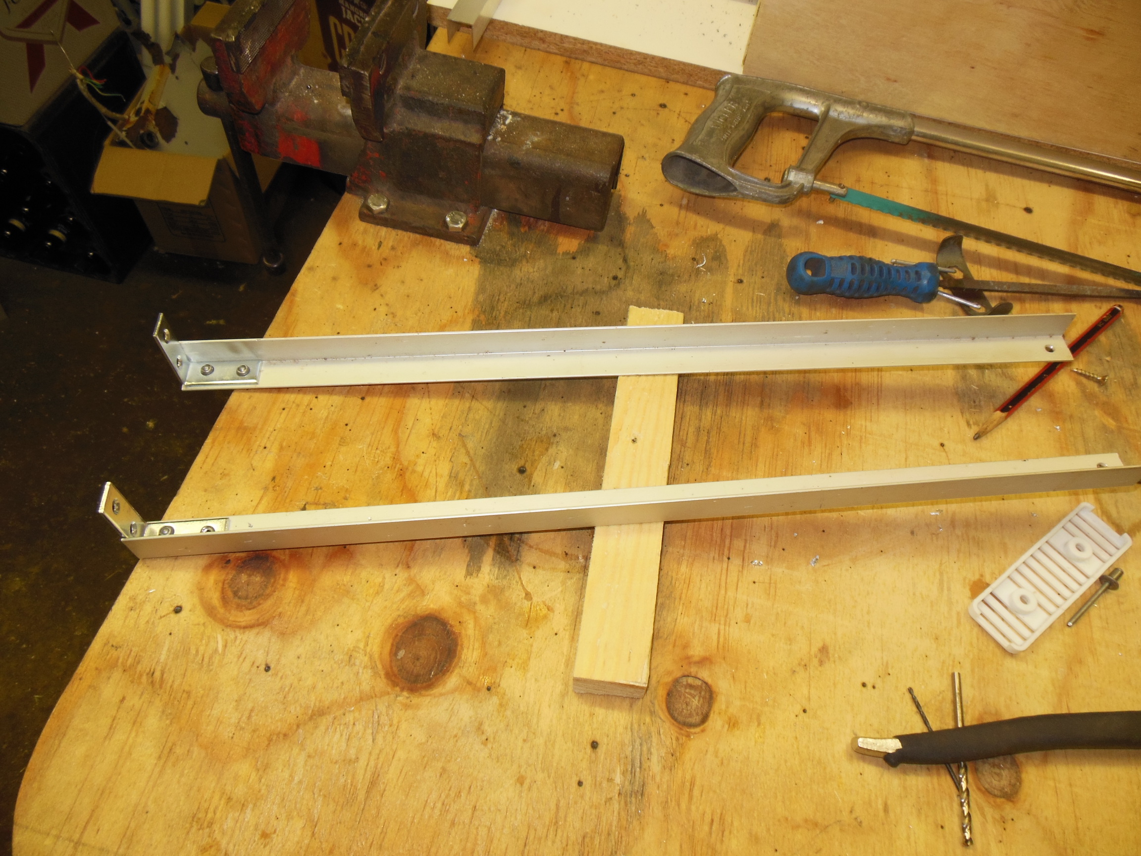
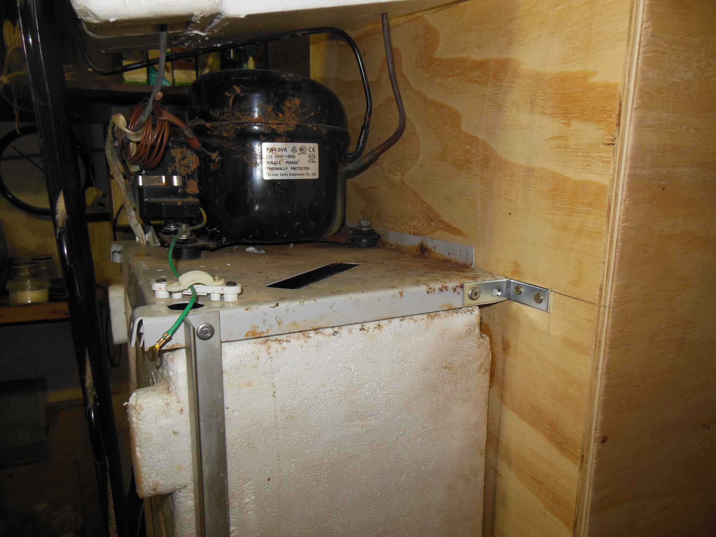
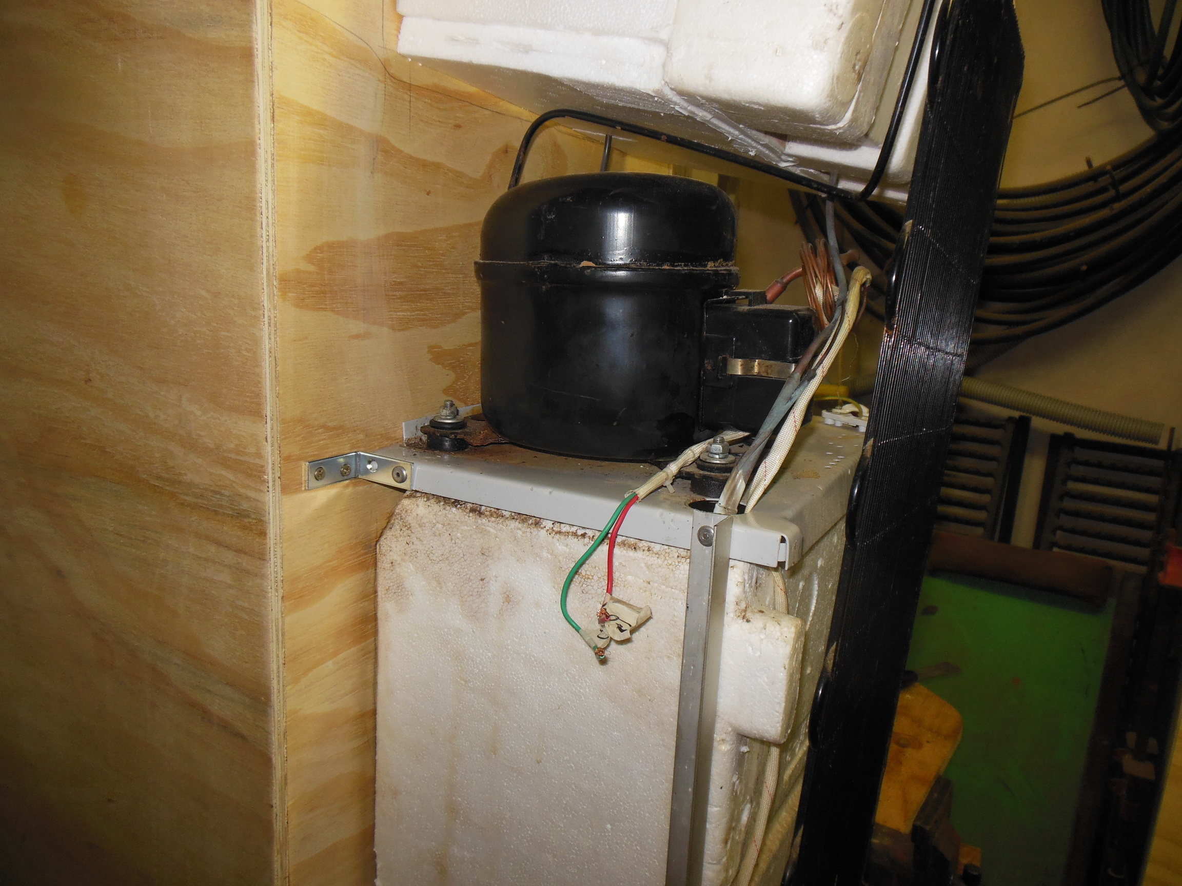
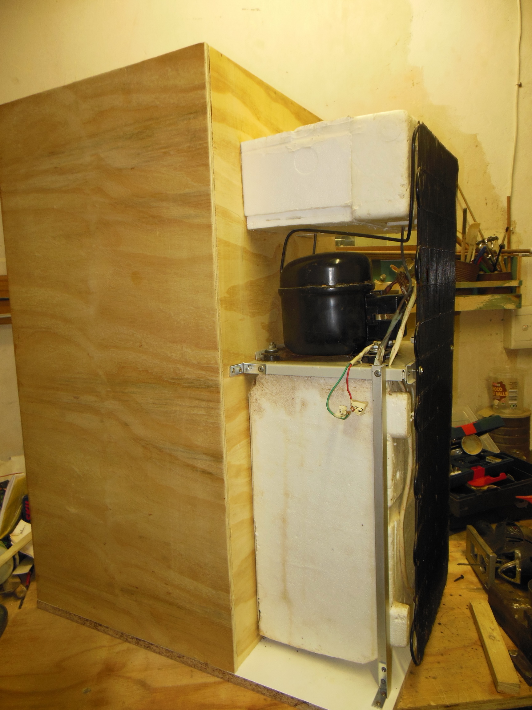
Bought some 40mm x 15mm galvanized angle brackets, mounted two onto the rear panel and riveted them to the compressor mounting plate. Then cut some 19mm aluminium angle bar to length and riveted an angle bracket to each to make the rear compressor mounts. Screwed them into the baseboard and riveted to the compressor mounting plate. Now the compressor is solidly mounted.

rear_compressor_mountings.jpg

Photo 11 - Freshly fabricated compressor mounting bars.

compressor_mountings_right.jpg

Photo 12 - Right side view of the mounted compressor plate.

compressor_mountings_left.jpg

Photo 13 - Left side of the compressor mountings. Managed to drill the rivet hole for the rear mount without hitting the chiller lines by inserting a piece of flat steel bar as a shield.

With the compressor secured, it was time to mount the chiller boxes onto the rear panel. The bottom one has a hard plastic shell, so it was pulled into place with a few chipboard screws from the inside.

lower_chiller_box_mounted.jpg

Photo 14 - Lower chiller box secured to the rear panel.

The upper box is a polystyrene box and chipboard screws won't work. So a bead of silicone sealer was run around the outside of the port and the box pushed into place and held temporarily with a couple of long screws.

upper_chiller_box_mounted.jpg

Photo 15 - Upper chiller box mounted and silicone sealed in place.

To be continued in another post as I have too many pictures.
 
Continued from the previous post.

With the entire chiller assembly mounted, I remounted one of the frame bars from the dismantled water cooler onto the compressor plate and secured the radiator panel to it.

mounted_compressor_chiller_right.jpg

Photo 16 - Fully mounted chiller assembly from the right.

mounted_compressor_chiller_left.jpg

Photo 17 - Fully mounted chiller assembly from the left side.

chamber_mounted_chiller_boxes.jpg

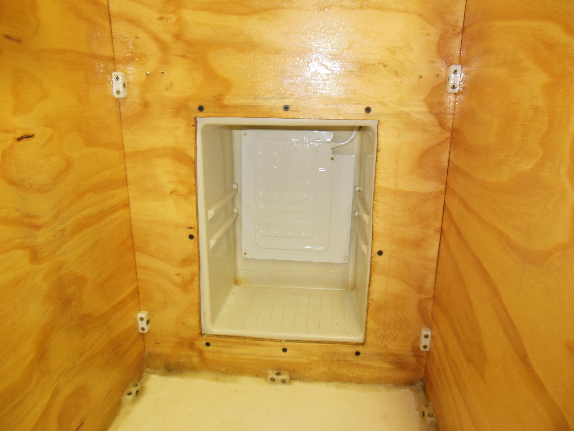
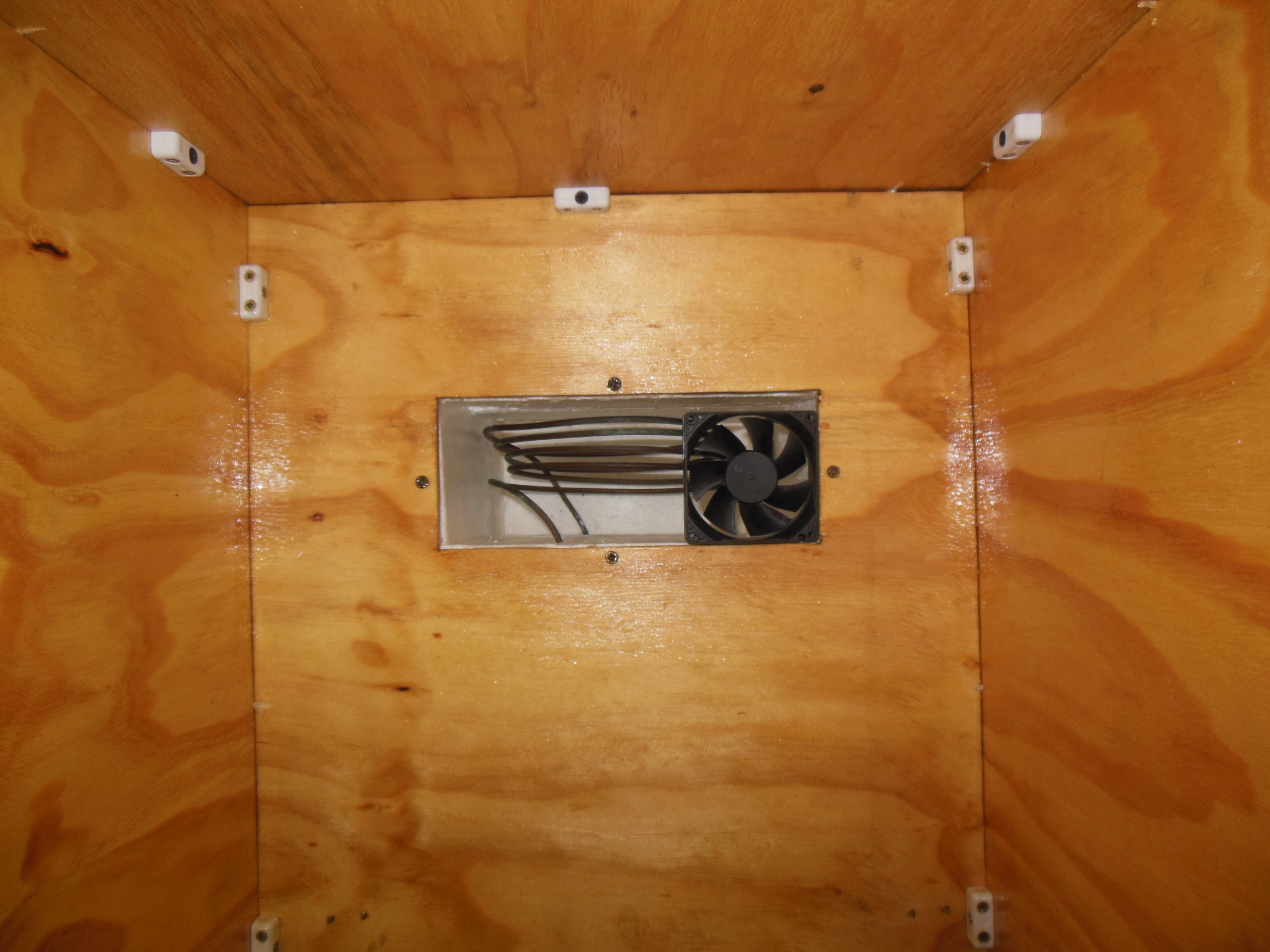
Photo 18 - Fully mounted chiller assembly from inside the chamber. Note the fingerprint trapped under the polyester layer on the baseboard.

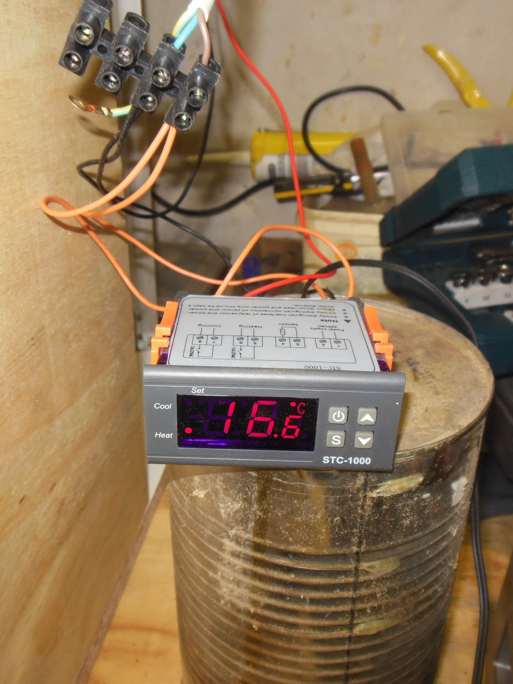
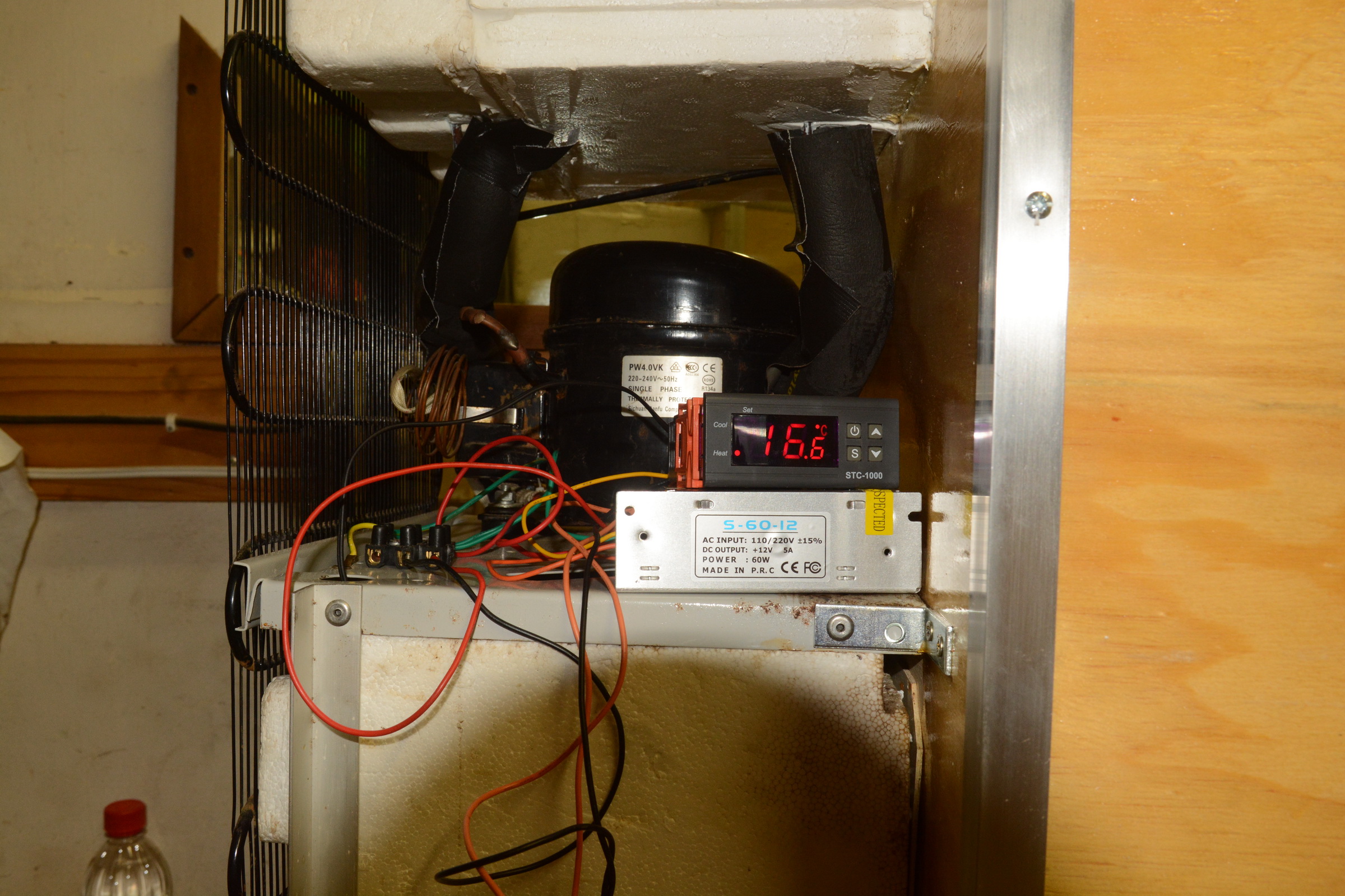
After all that fiddling and moving of chiller pipes, it was now necessary to test the chiller to make sure the danged thing still works. Grabbed the STC 1000, still wired from the testing after the dismantling phase, and wired it to the compressor wires. Switched it on and discovered that the air temperature in the workshop was a balmy 32°C, one of those ridiculously hot and humid summer days.

chiller_test_small_start.jpg

Photo 19 - STC 1000 at the start of the chiller test.

chiller_test_small_end.jpg

Photo 20 - STC 1000 once the upper chiller box reached the set temp

The cooling test was done with the probe inside the upper chiller box and with both ports into the main chamber blocked off as the chamber is still open to the air. Took about 12 minutes to drop from the 26°C to the 17°C set point.

Next is to finish off the fibreglass sealing at the bottom of the chamber, it needs a second coat of resin, apply the polyester resin coat to the plywood around the upper port and start making the top of the box, the compressor assembly covers and the door.
 
Awesome work! My first fermentation chamber was a wall AC unit in a boxed-off area. Yours is much more polished and looks like it will work well!

Cheers!
 
Quick update on the project. Spent most of the working time on the chamber varnishing and finishing the various faces. Decided not to post repetitive pictures to see who could spot the difference between two and three coats.

varnished_front_upper_view.jpg

Photo 21 - Upper view of the top and sides with their three coats of varnish.

varnished_rear_view.jpg

Photo 22 - Rear view of the chamber with three coats of varnish applied. Also note the bottom bracket installed for the radiator.

Once the varnishing was completed, some insulation was temporarily wrapped around the cold circuit pipes that were exposed at the back of the chamber. A cooling test with one 80mm circulating fan was undertaken and based on those results, separate circulation fans are needed for the upper and lower chiller boxes. Will go hunting for another defunct PC power supply to salvage one from this week.

Started on the aluminium edge trim for the chamber working to complete one side today before the heat drove me from the workshop. Depending on the type of edge, it is either 19mm square U channel or 19mm angle, both held in place with 3.5mm x 10mm self-tapping cheese head screws.

bottom_alu_trim.jpg

Photo 23 - Detail of the bottom trim. Right side is the U channel and left side is the angle.

side_alu_trim_stage_1.jpg

Photo 24 - Partially completed side trim. Top trim and rear vertical trim is in place.

side_alu_trim_stage_2.jpg

Photo 25 - Upper view of completed side trim. Butt joints where the vertical meets the horizontal because I wasn't going to try and mitre 45° cuts in two directions. Top trim has 45° mitre cuts for the top circuit.

side_alu_trim_stage_3.jpg

Photo 26 - Lower view of completed side and lower front trim.

Tomorrow, continuing on with the trim application on the top and other side. Following that, looking at the door structure and how to hinge and latch it.

Also to-do is a 35mm layer of expanding polyurethane foam on the bottom to provide an insulation layer that is hard enough for the fermenter to sit on and to investigate the insane feasibility of using same expanding foam to do the sidewall and roof insulation layers instead of either the polyester fiber blanket or polystyrene sheeting as discussed previously.
 
I would think 2 is enough for that space, you may have to maybe play with the angle to get the right amount of flow.
 
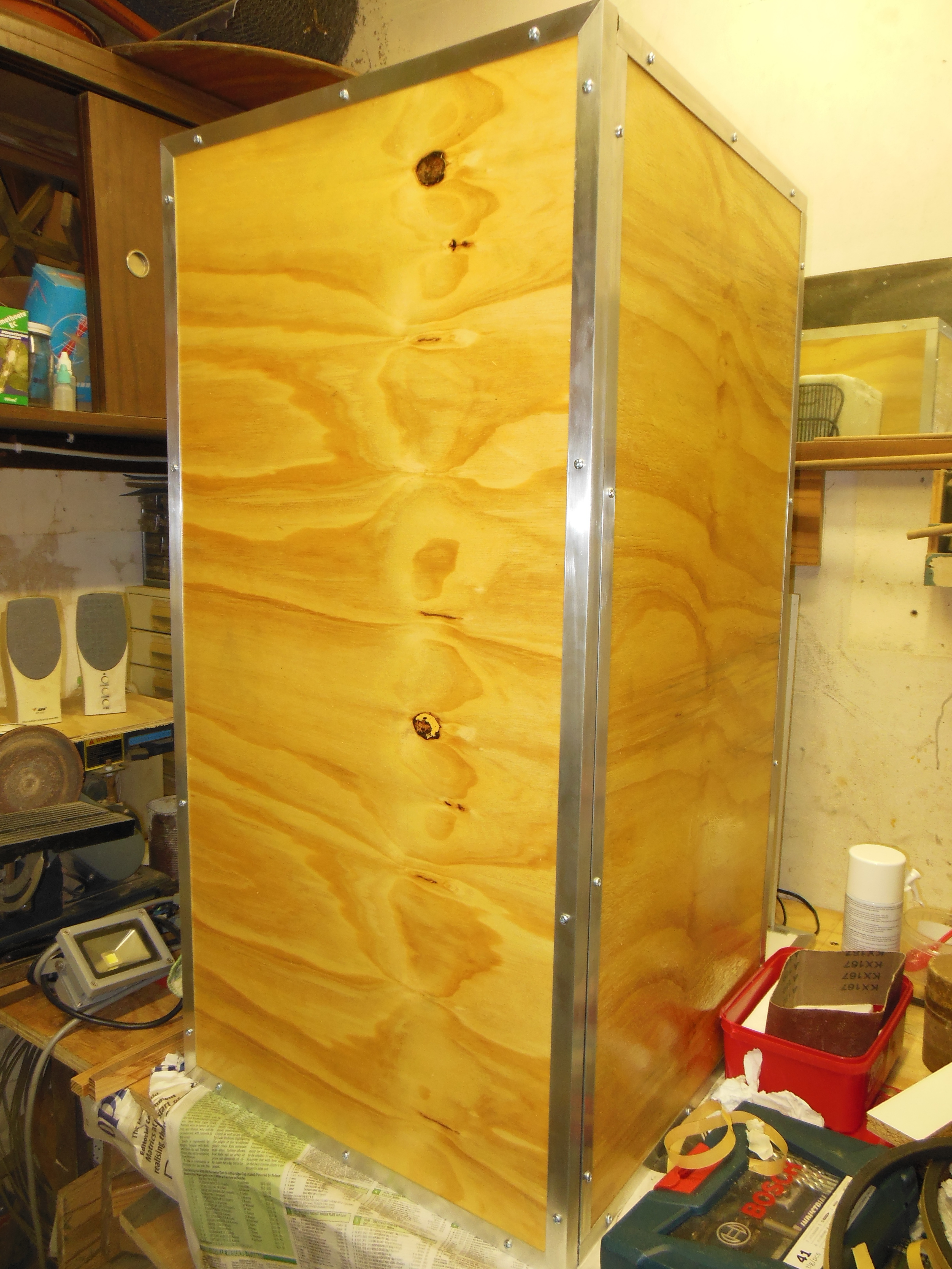
Finished fitting the rest of the trim, closed the last couple of gaps in the upper chiller box and positioned the fan for the upper chiller box.

trim_completed_1.jpg

Photo 27 - Left side view.

trim_completed_2.jpg

Photo 28 - Frontal view

trim_completed_3.jpg

Photo 29 - Right side view

upper_fan_position.jpg

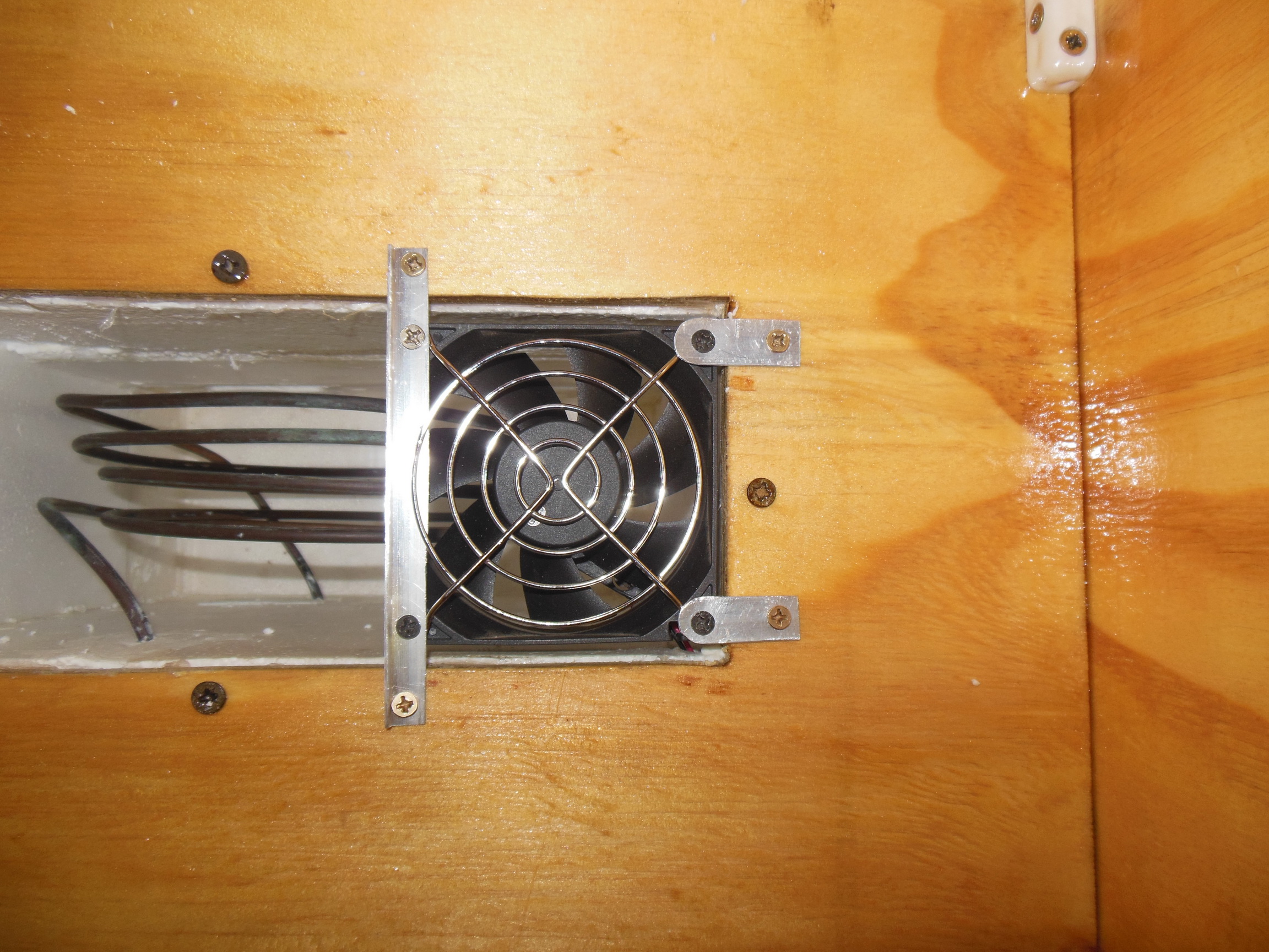
Photo 30 - Mounting position for the upper chiller box fan. Wires routed outside via a small hole in the chiller box.

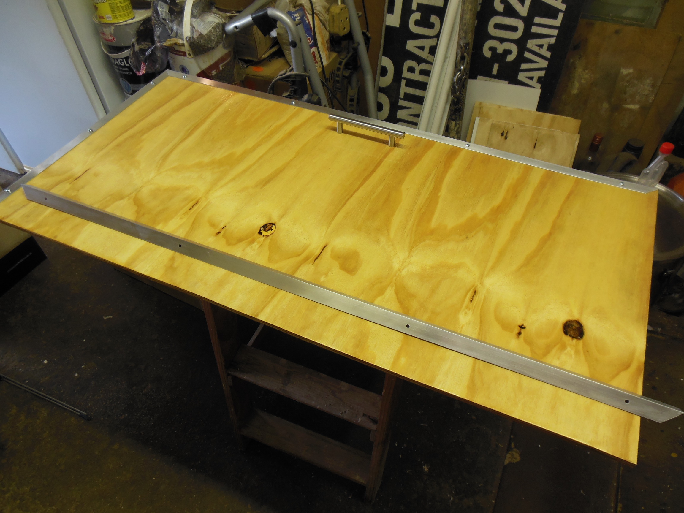
Door needs to be cut to size, sealed with polyester resin on the inside face and varnished on the outside. Also hunting suitable aluminium profile to edge the door nicely.

Coming along nicely I think.
 
I'm really interested to see how this works when it's done, I have a water cooler that's in good working order and I no longer need. I'm keen for the project if it works!
 
This looks incredible! What ingenuity! Great job! Cant wait to see the finished product.
 
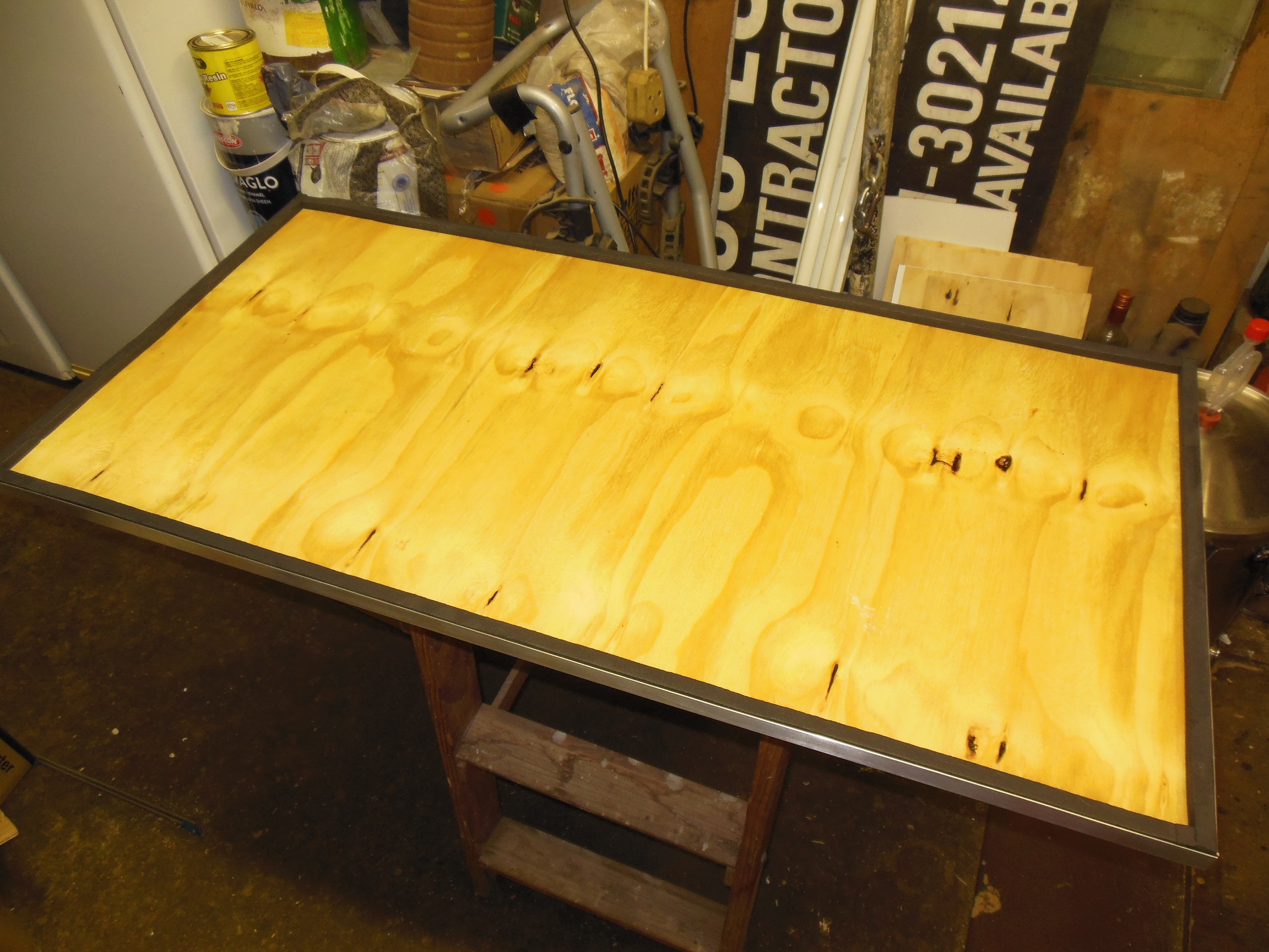
Quick update, slow movement again. Got the front door cut to size, sealed, varnished and ready to apply the trim.

door_1.jpg

Photo 31 - Door with first trim fixed into place. All going according to plan to finish the door today.

door_2.jpg

Photo 32 - Door with one long edge trim fitted and with the second long edge ready to mount.

Ran into an issue with the second long edge, put the trim in place and found that there was significant rocking along the length. Ran a straight edge along the door and found a 12cm long section that was up to 3mm outside the straight edge. Rasped it down to flat and reapplied the varnish. Going to put the second and third coats back on the rasped section tomorrow before I can fit the trim strip. Grrrrr.

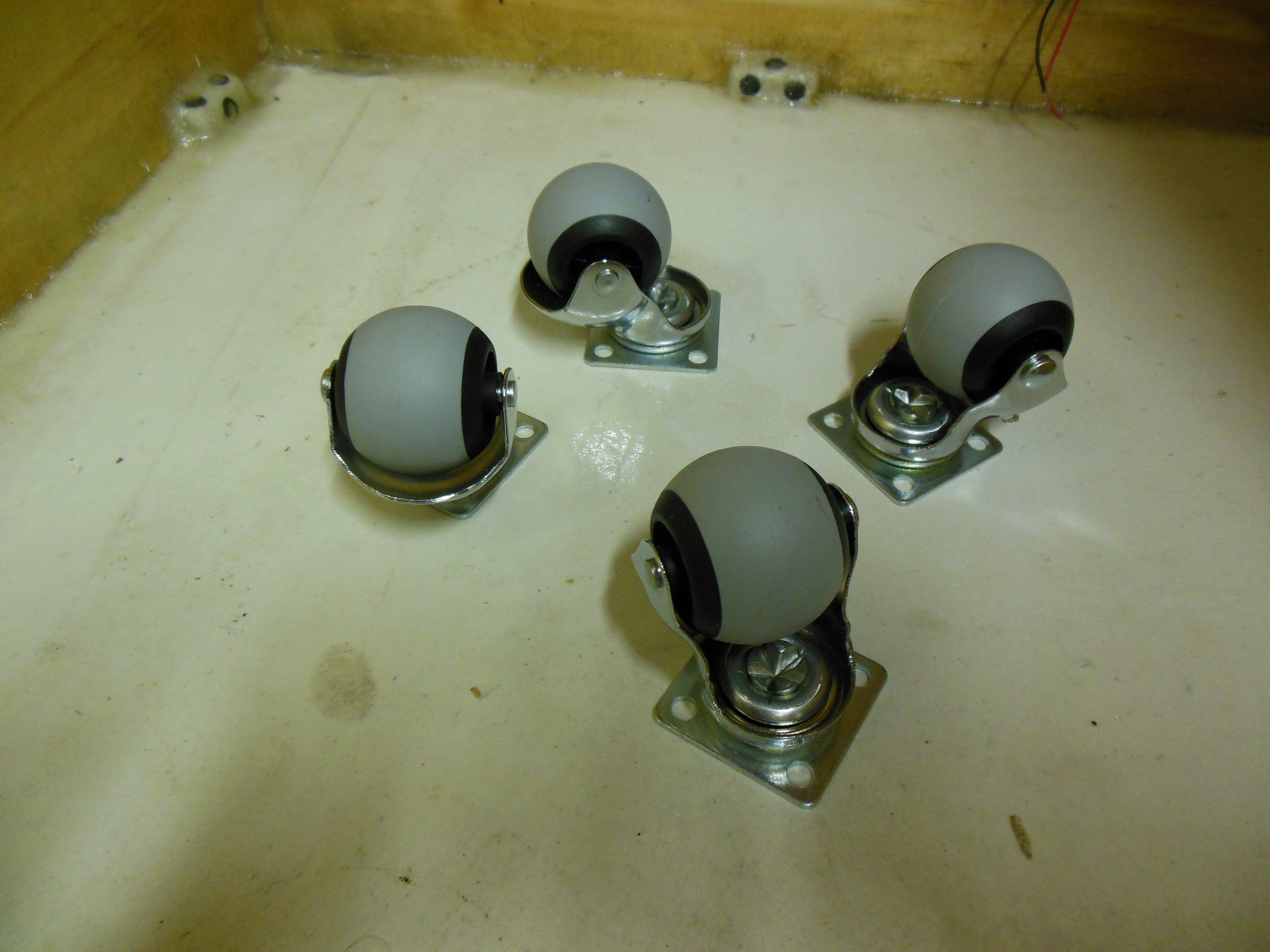
casters.jpg

Photo 33 - Casters to allow the whole chamber to be wheeled around.

Got hold of the casters and mounting hardware for the chamber. Rubber wheels to be secured to the baseboard with 5mm self tappers.

Also got hold of the second fan, am waiting for the delivery of a pair of finger protection grills as I've already hurt myself catching a spinning fan as it fell. Also in the same order is a miniature 12V power supply for the fans and a DC to DC USB converter board to power the RPi that records the Tilt from the 12V supply.

both_fans.jpg

Photo 34 - Both fans roughly in place and needing mounting.

More to follow in the next couple of days.
 
More updates. Got the door finished and a layer of the expanding spray foam on the bottom. It shaves well with the rasp and hacksaw blade, but is still kind of saggy under load. Will see how it goes after a day or so to see if it gets harder all the way through. Otherwise, I've found where I can get expanded polystyrene sheeting of a suitable size.

door_trim_side.jpg
Photo 35 - Door with all trim installed.

door_inside_seal.jpg
Photo 36 - Inside of the door with the foam seal tape in place. Might have to double up on the width to fit the insulation sheeting into the doorway.

door_pretending_chamber.jpg
Photo 37 - Door pretending to be attached to the chamber. Held in place by 1/4" strip of Gorilla tape.

sprayfoam_base.jpg
Photo 38 - Expanding spray foam. Reached the right depth I wanted and it shapes well. Trial shaping in the back left. Bit saggy under pressure.

Next steps, procure some EPS sheeting, some latches to hold the door on and figure out the hinge mountings on the door.

Also, see what the spray foam does after a day of hot curing, 28°C days at the moment and decide whether to complete the spray or replace with EPS sheeting.
 
Today's partial update. Removed the expanding spray foam as it wasn't up to supporting the load of a fully loaded fermenter. Started sagging a bit. So decided to go with EPS on the bottom as well. Hopefully that works.

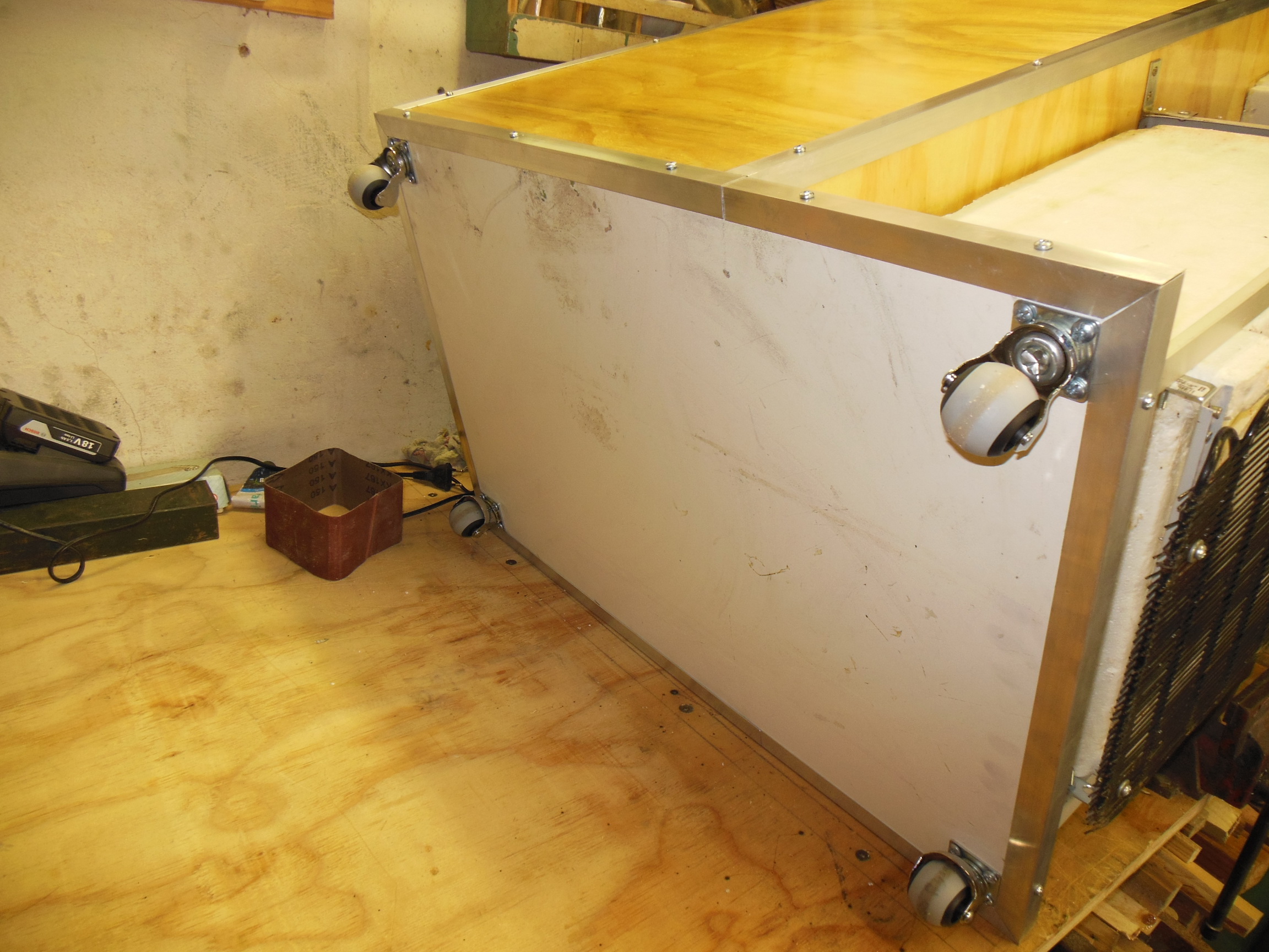
Mounted the casters underneath the cabinet and the two fans including finger protection grills inside. Started fitting the insulation, but the heat of the day beat me back eventually. Cooler and rainy weather tomorrow, so should be able to finish the insulation.

casters_mounted_2.jpg

Photo 39 - First two casters attached to the base.

casters_mounted_1.jpg

Photo 40 - Close-up details of one of the casters.

casters_mounted_3.jpg

Photo 41 - All four casters mounted on the base. Can now swing it around on the bench easily.

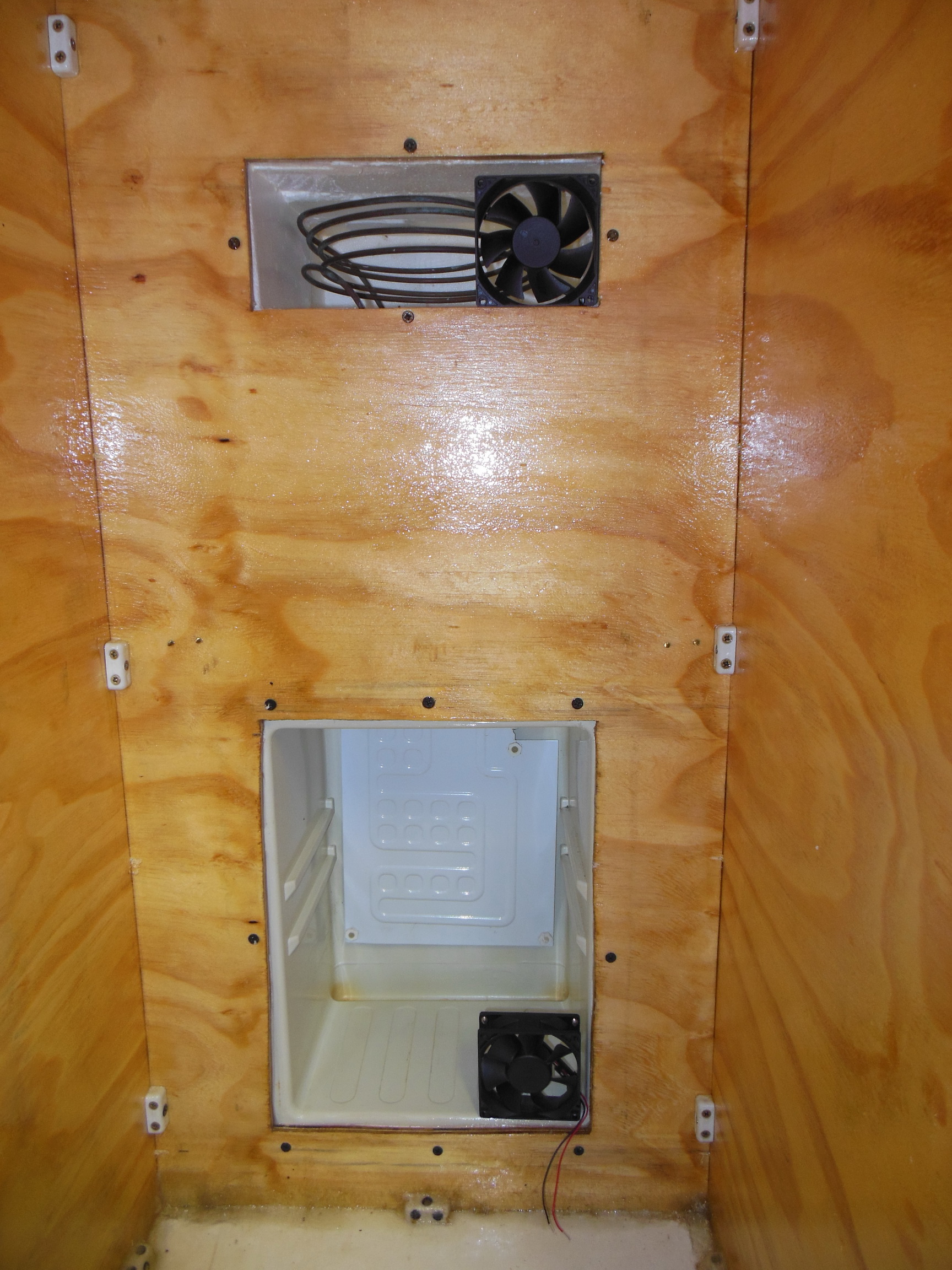
upper_chiller_fan_mounted.jpg

Photo 42 - Upper chiller fan mounted and cable routed out.

lower_chiller_fan_mounted.jpg

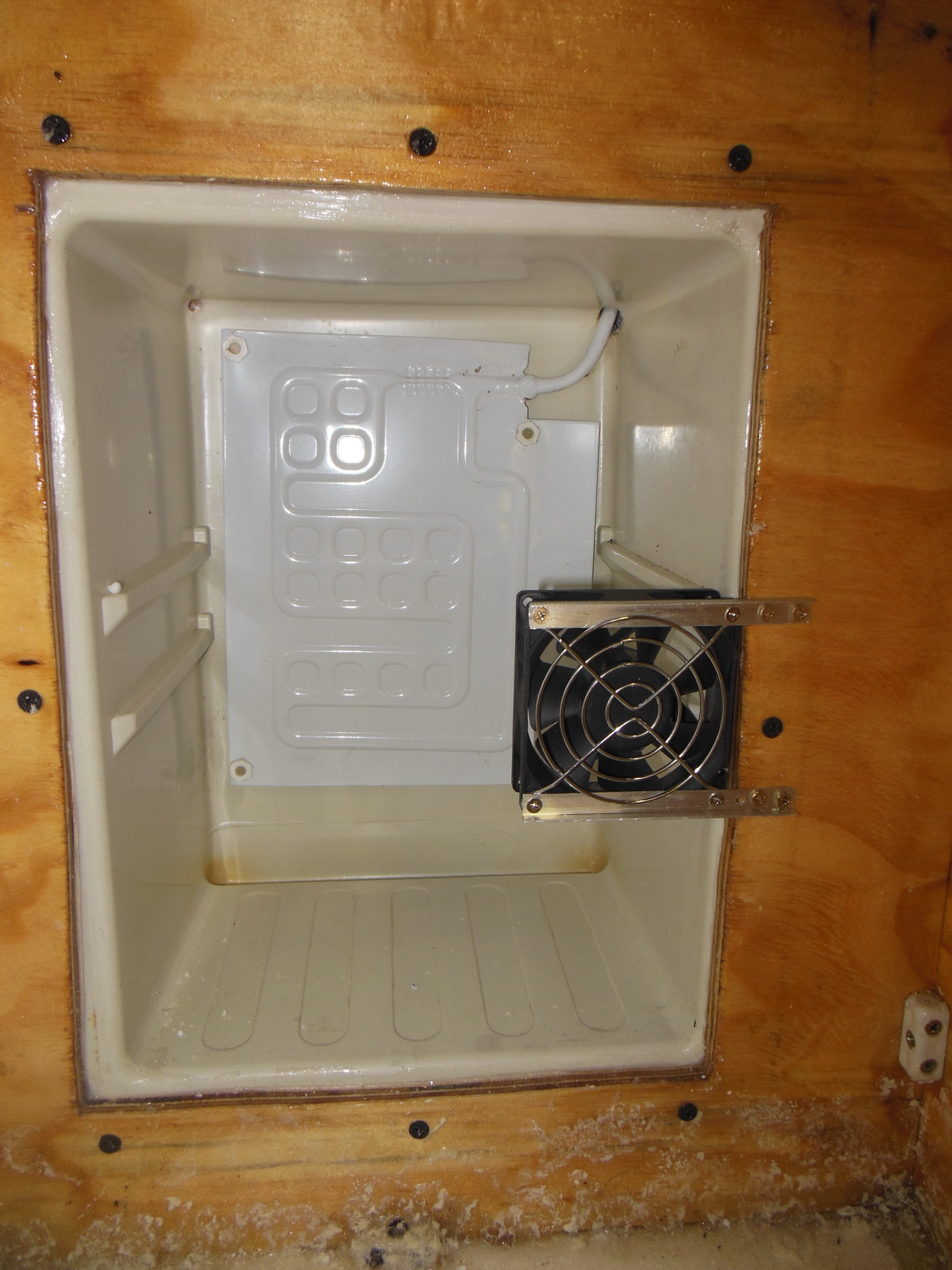
Photo 43 - Lower chiller fan mounted.

lower_chiller_fan_detail.jpg

Photo 44 - Close-up details of the lower fan mounting.

chiller_fans_mounted.jpg

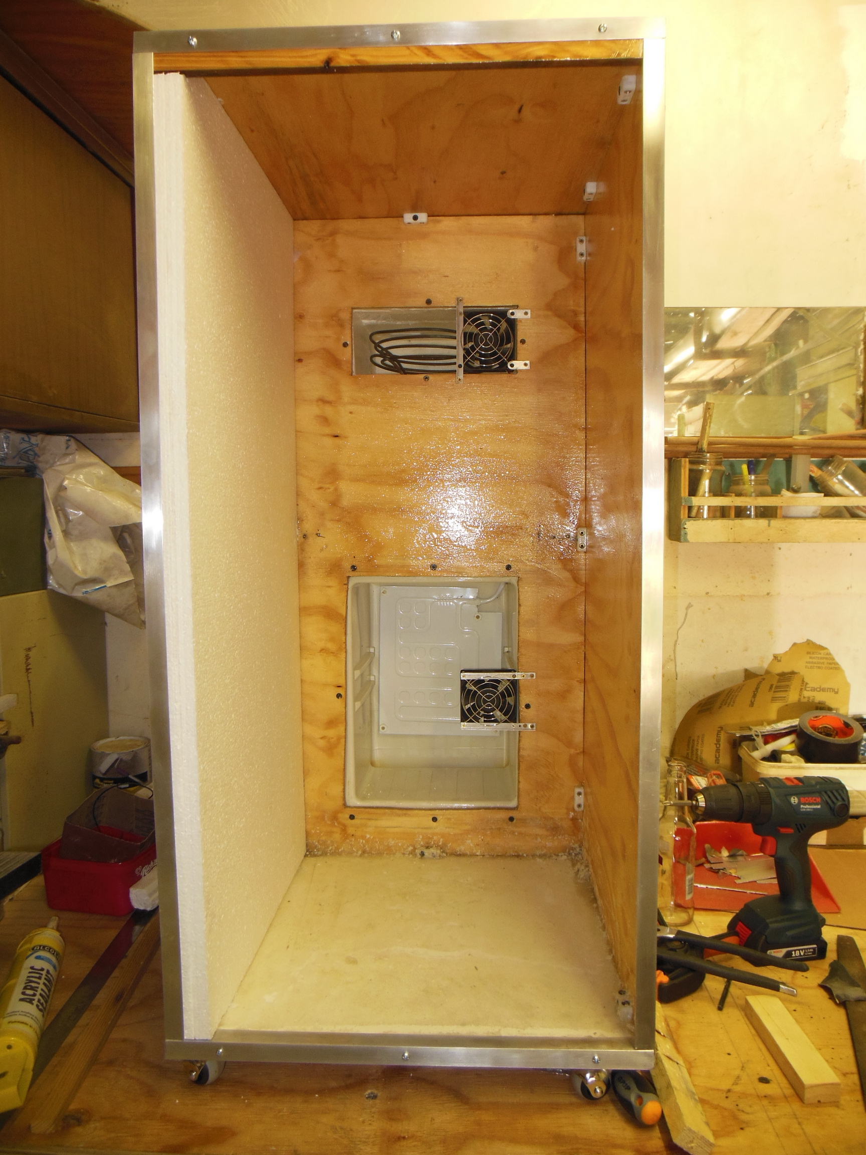
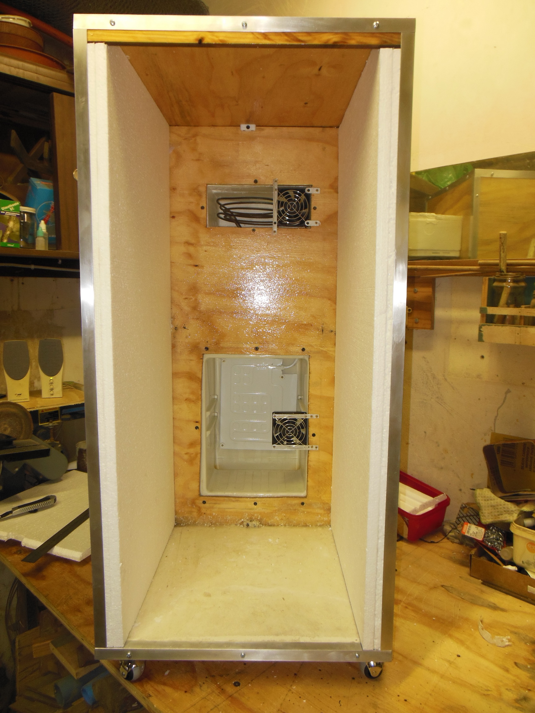
Photo 46 - Cabinet with both fans mounted and the left side EPS insulation cut and fitted.

Once all the internal insulation is in place, the door insulation panels will be fitted so the two sections slot together as the door closes. Once that is finished, temporary wiring needs to be done before a fermenter will be placed inside, the door strapped into place and a cooling test done. Almost there.
 
Got it to run and hold temperature today.

Finished the installation of the side, bottom and top insulation, wired up the fan power supply and the STC-1000 to the compressor and ran a closed chamber test. Dropped a bottle of water from 22.6°C to 18.0°C set temperature in under two hours.

wall_insulation_installed.jpg

Photo 47 - Installed the right side insulation next. Same process as the left.

floor_insulation_beveled.jpg

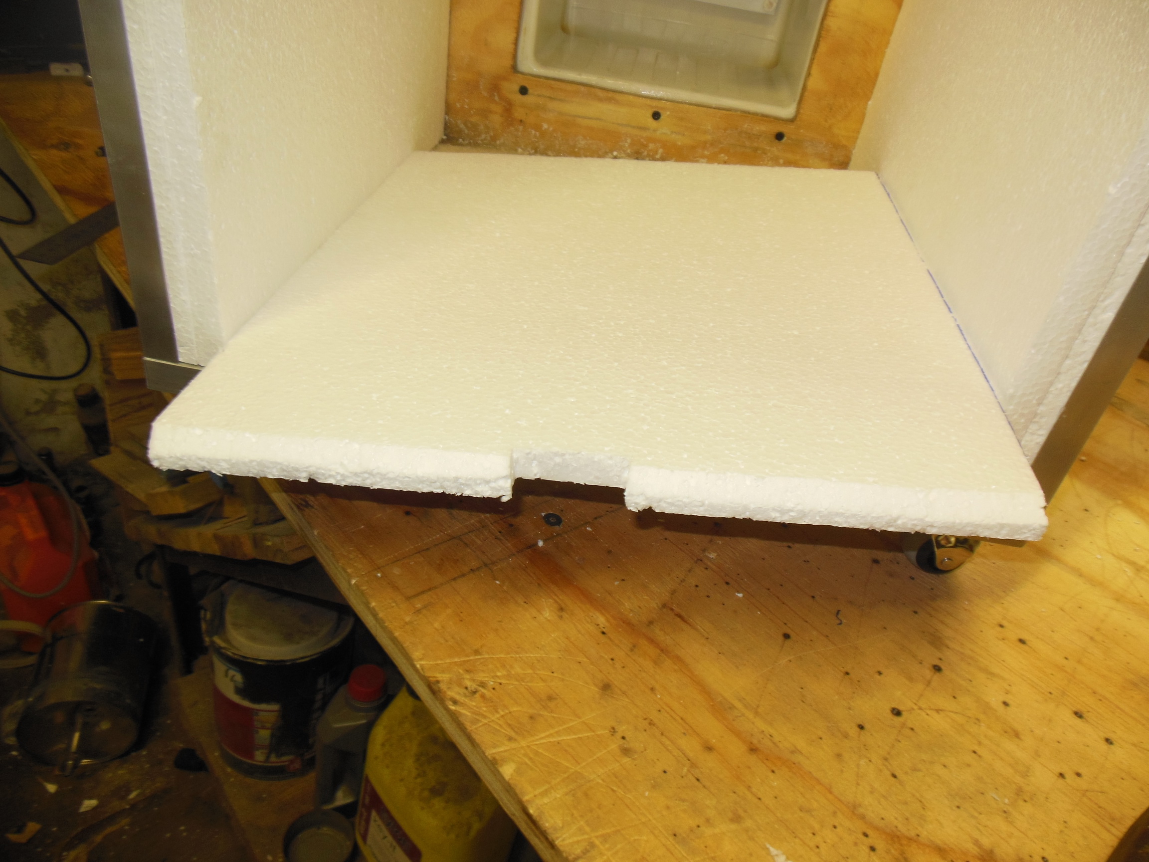
Photo 48 - First later of the bottom insulation. Beveled to fit around the fibreglass sealing edge.

floor_insulation_installed.jpg

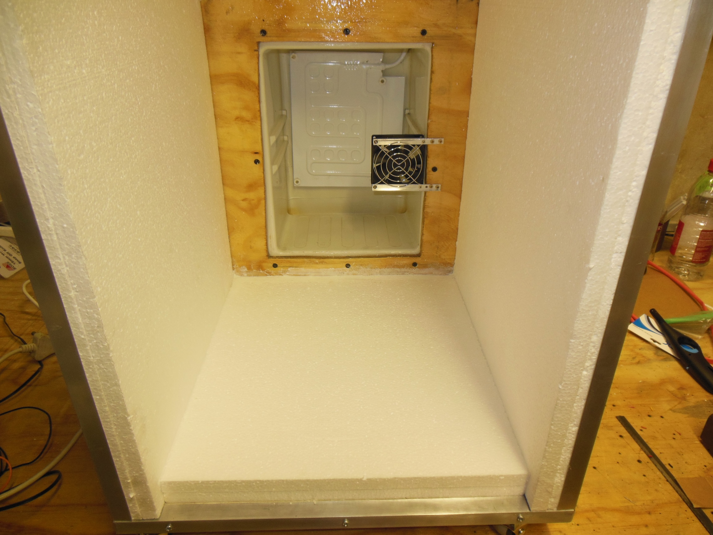
Photo 49 - Bottom insulation installed and sealed in place. Recessed to allow for the door insulation to slot in.

roof_insulation_installed.jpg

Photo 50 - Roof insulation installed and recessed.

side_insulation_installed.jpg

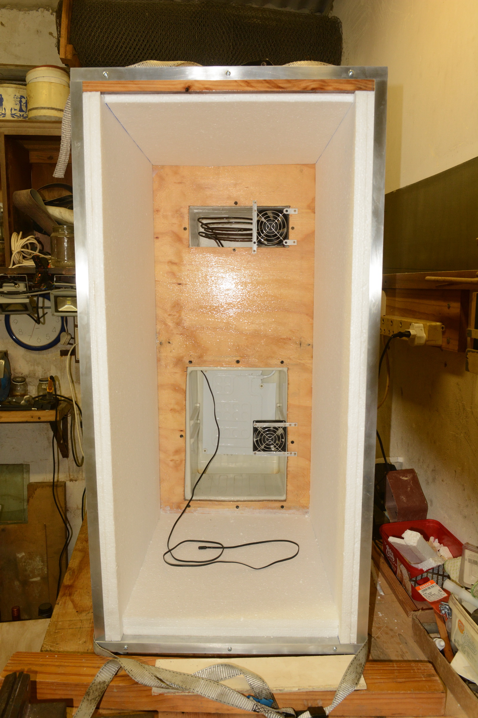
Photo 51 - Full view of the side, floor and roof insulation completed. STC 1000 probe run through an old thermostat hole in the mini-fridge chamber.

fans_wired.jpg

Photo 52 - Fan wiring soldered, heat-shrunk and "neatly" routed.

chamber_test_22.6.jpg

Photo 53 - Start of the cooling test. 22.6°C at the time of the photo.

chamber_test_16.6.jpg

Photo 54 - Post cooling test. Sensor in bottle of water reached 18.0°C and shut off the compressor. Air temp in the chamber itself was at 16.6°C

So the whole thing appears to work reasonably. Still need to test with a full fermenter and see how it handles the changed airflow patterns around the fermenter. That needs to wait until I finish crafting the front and back insulation and get the door mounted.

Had a casualty today, the Nikon S6300 point-n-shoot that's been taking most of these photos had a lens drive gear that's been giving issues for a few years now finally let go. Was a nice lightweight camera that worked nicely alongside the big Nikon DSLR which I've reverted to. And apparently Nikon only does a small handful of compact point-n-shoot cameras now.
 
Looks awesome so far! Glad you were able to get a test in and see where it's at. It's a bummer your trusty cam died on ya. Excited to hear how it does with a loaded fermenter.
 
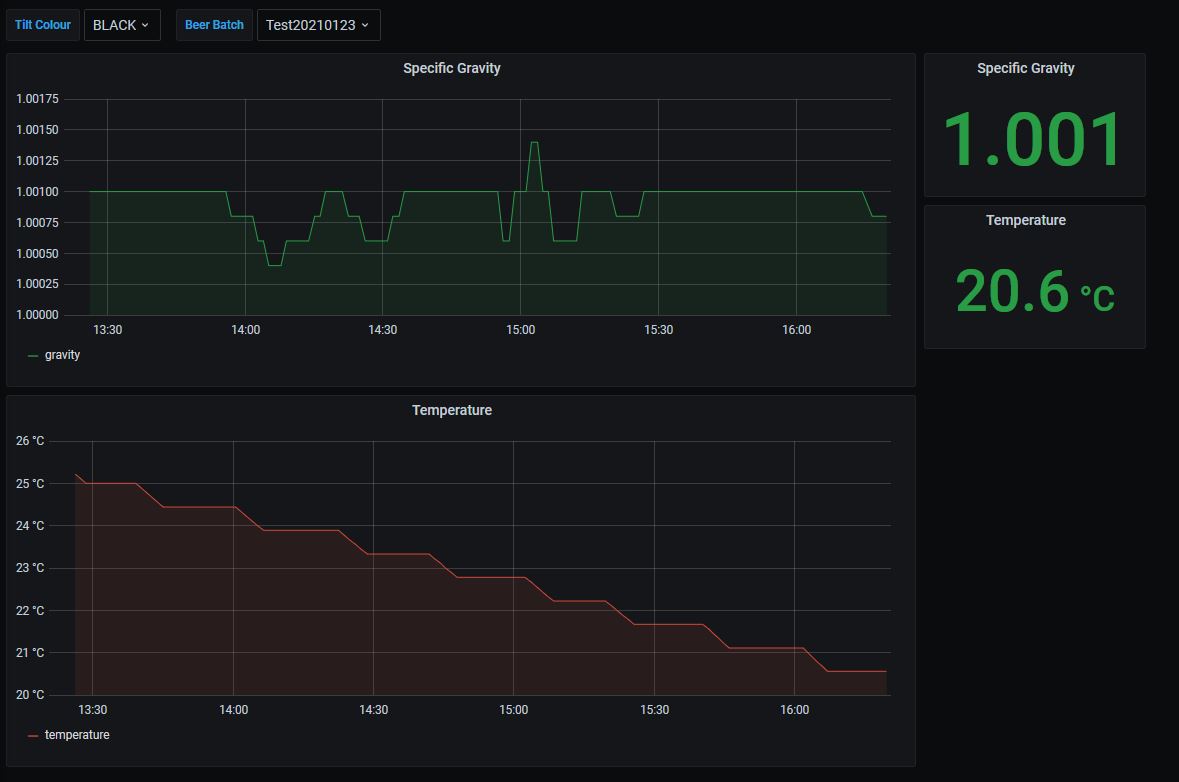
Running a temperature maintenance test. Seems to be pretty good at the job.

initial_chilling_plot.jpg

Diagram 1 - Tilt plot of temperature inside the fermenter for the first 3ish hours.

second_chilling_plot.jpg

Diagram 2 - Tilt plot of temperature inside the fementer with steady maintenance from about 17h20 onwards.


I think I need to insulate the sensor a bit better than it is now, there is still some air-temperature swing happening on the STC-1000 display.
 
More temperature and cooling tests with graphs from the Tilt.

First, dropping to 18°C and holding for several hours, changing the STC-1000C's differential from 0.5° to 1° with no visible difference to the temperature as measured inside the fermenter by the Tilt. Duty cycle in holding mode with differential of 0.5° is about 2 minutes on, 7 minutes off and differential of 1° is about 3 minutes on and 13 minutes off.

temp_maintenance_plot.jpg

Diagram 3 - Temperature maintenance plot from Tilt data.

Next I began a series of stepped temperature drops to see how low I can get the fermenter. Following online advise to use steps to reduce the load on the compressor. First I set the target temp to 12°C and let it reach there and get to the maintenance duty cycle, then dropped it to 9°C. When I went to bed last night, I switched the compressor off to see how well the insulation contains the temperature. It climbed back from 10°C to 14° over 7 hours without maintenance.

temp_stepped_drops_and_insulation_plot.jpg

Diagram 4 - Stepped temperature drops and insulation cold retention test plot.

Today I've been running from the 14°C plateau stepping down to 12°C, 9°C, 5°C and then to 3° letting the fermenter reach equilibrium each time. It is currently on the step to 5°C. Will post those results as soon as they are completed.

It does look like this will be able to cold-crash nicely as well as maintaining the temperature profile for the actual fermentation without taxing the small compressor. A power monitor on the compressor shows it is pulling 0.177kVA at 230V when running.

Going to start building the power system housing now and looking at the effect of active air movement on the radiator of the chiller.
 
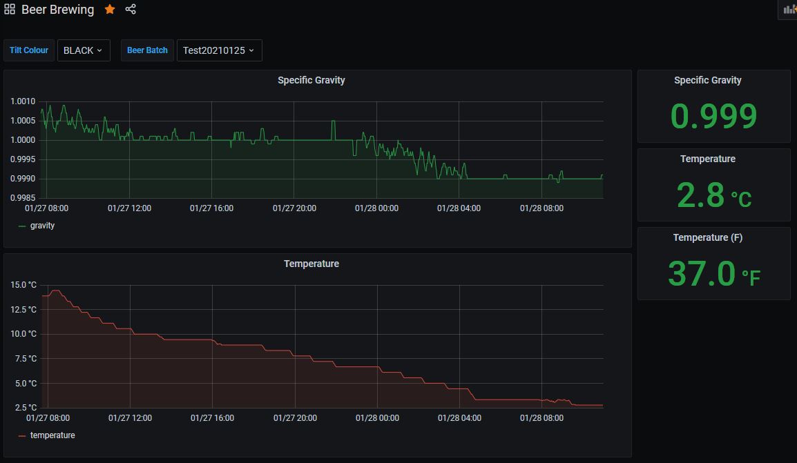
Testing finished for now. I am a happy camper.

Ran a cold-crash test and got it down from 14°C to 2.8°C as measured by the Tilt over a 26 hour period. Forced air cooling of the radiator is definitely needed to both ramp up the chill speed and to get it down to below 6°C without running the compressor completely. I will put in a couple of 50mm blower fans that are used on 3D printers to push flow over the radiator.

temp_stepped_cold_crash_plot.jpg

Diagram 5 - Cold crash temperature plot from the Tilt.

I powered off the compressor system and then let it warm up from any ambient source. It took 6 hours for the Tilt to warm from 2.8°C to 8.9°C and that was only the upper levels of the fermenter water. After removing the fermenter, I used my digital thermometer to check and found the Tilt was accurate at the surface, but deeper in the water body, the temperature was still at 6°C, so there was some temperature stratification going on. The STC-1000C reading was 11.9°C from the sensor strapped to the fermenter and covered with some pipe lagging material at the same time.

temp_power_off_ambient_warming.jpg

Diagram 6 - Temperature rise with compressor off and chamber seal by the Tilt.

Still working on the electronics enclosure now that I can remove the STC-1000C and mount it. Also need to work on some joint sealing and the drains for condensation in the chiller boxes.
 
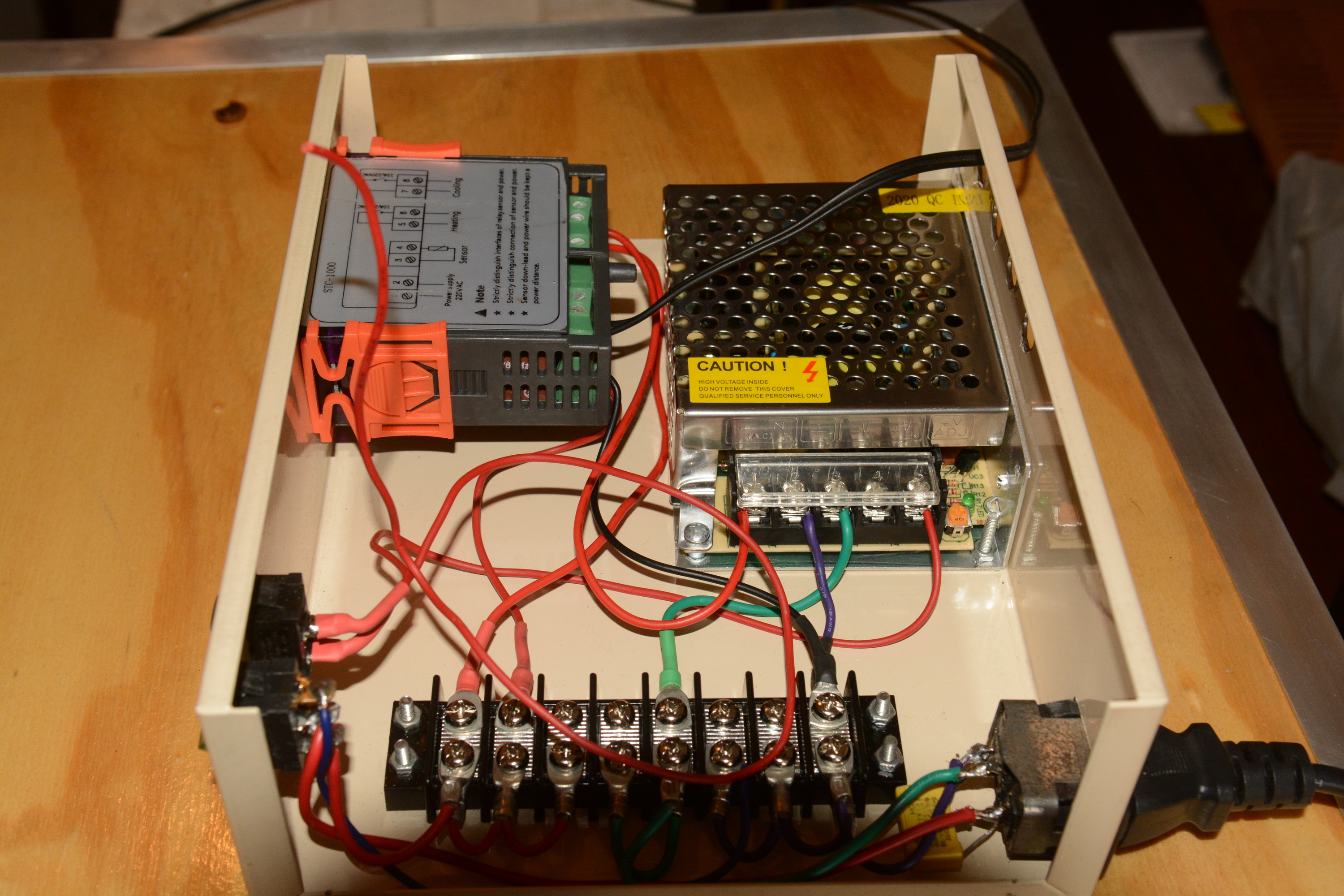
Now building the controller box. Cut the holes for the various modules and filed to fit, drilled the mounting holes and cleared out all the metal fragments that magically appeared when drilling.

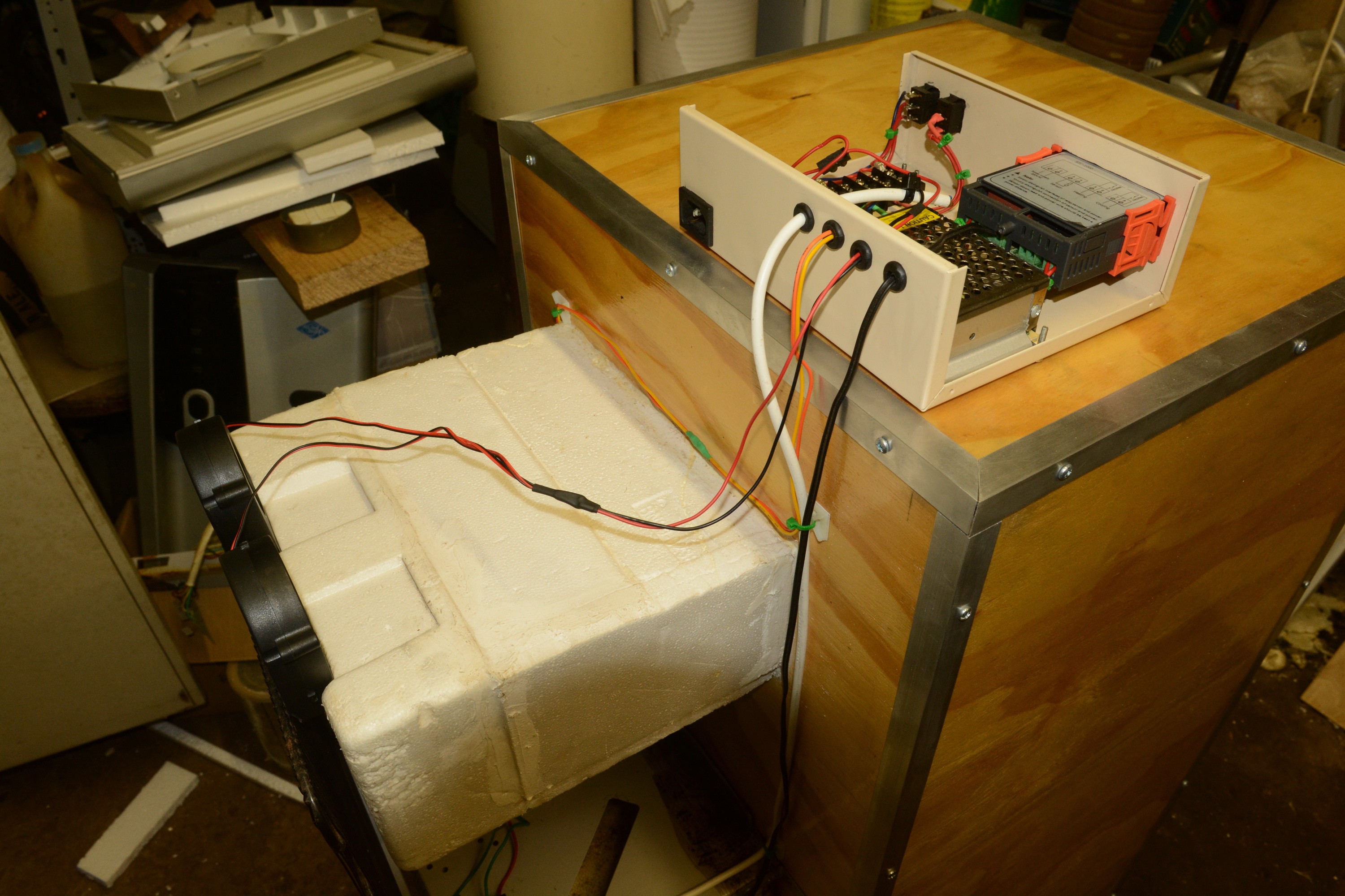
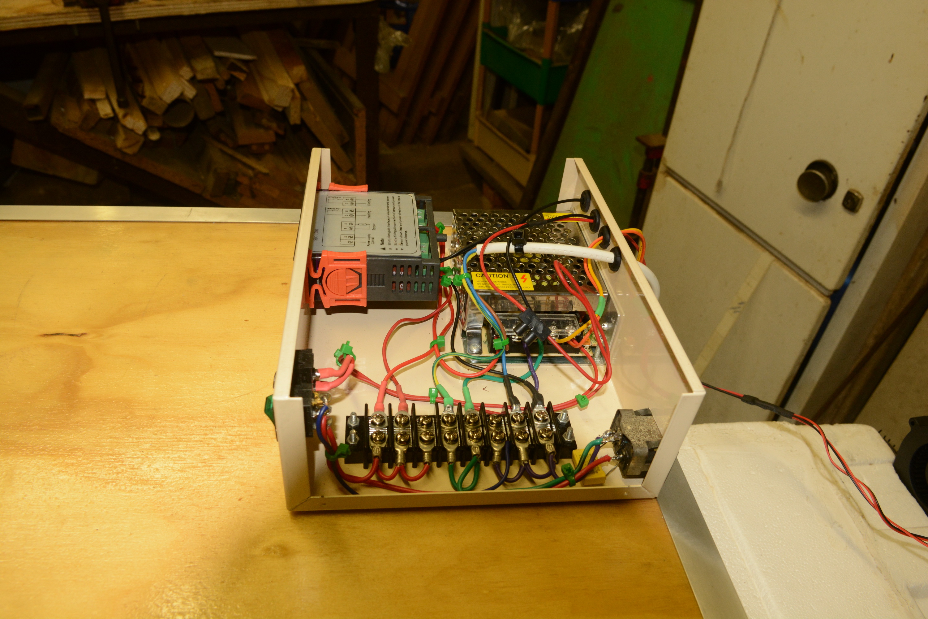
Very simple circuitry, the STC-100C mounted on the front panel switching AC power to the 12V power supply and the compressor unit. Mounted a screw terminal block in the case and began wiring up. First two pictures are different stages of the wiring up process.

controller_inside_1.jpg

Photo 55 - Power input side wiring in place on terminal strip.

controller_inside_2.jpg

Photo 56 - Further wiring progress with cooling relay connected to live and then to the 12V PSU.

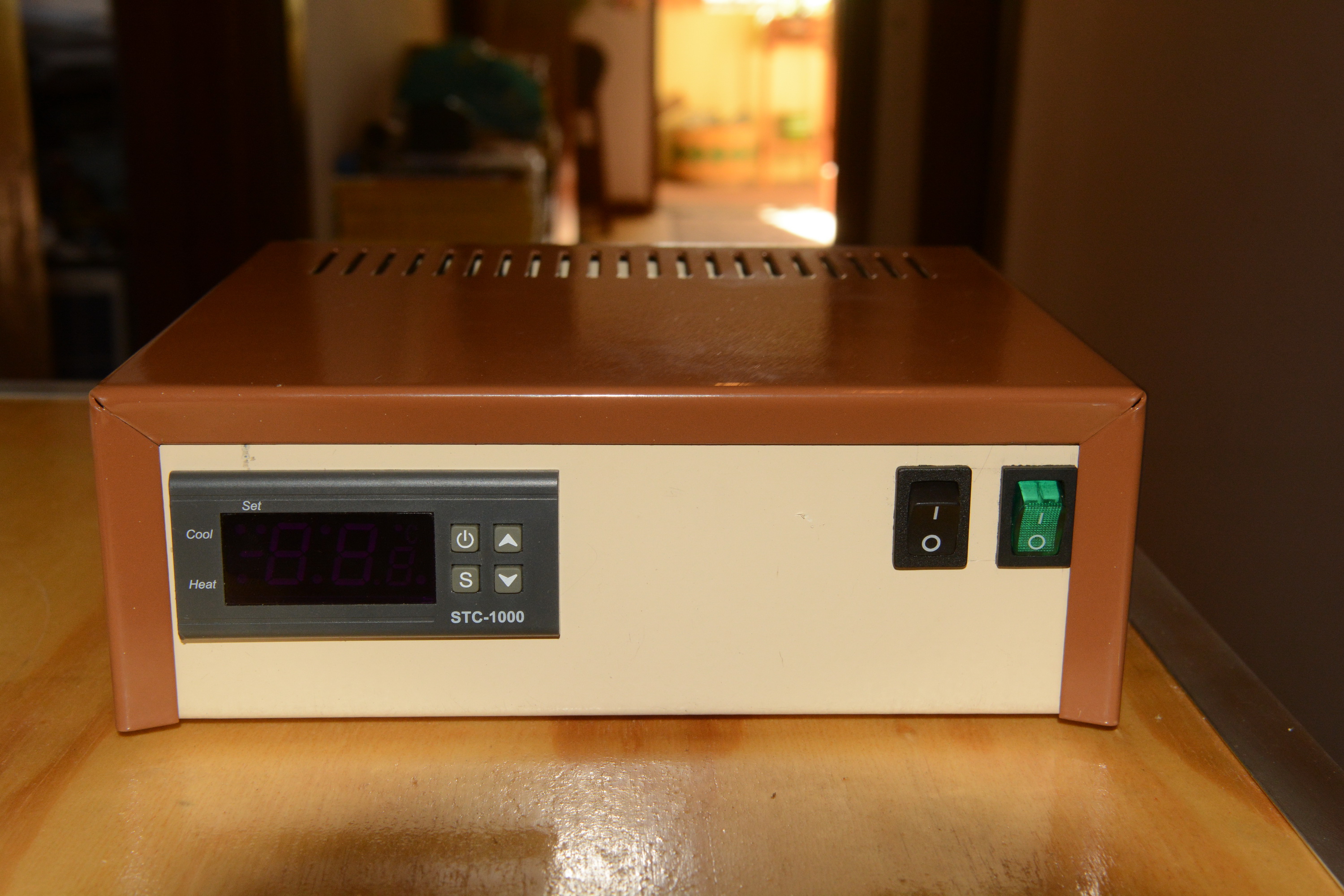
Ran a temporary hookup to the temperature sensor and powered it up. The STC-1000C is noisy when it doesn't have a temperature sensor connected. Ask my ears how they know. Controller ran as expected and closed the relay to power up the PSU and the compressor which wasn't connected.

controller_running.jpg

Photo 57 - Front shot of the controller running.

The green switch is the master power switch for the controller and the black switch is a 12V circuit to power the radiator blower fans when needed. The cooling tests done during the week showed the chamber able to hold fermentation temperatures without needing forced air over the radiator, but cold-crashing will need it.

Final shot is of the controller with the cover on.

controller_covered.jpg

Photo 58 - Controller with cover on.

Ran into an amusing design problem. I was going to power a dismantled car USB charger thingy from the 12V PSU so that the Raspberry Pi could be powered from the same place rather than running a second power cable. However I realized that since I am driving the AC into the 12V PSU via the cooling relay contacts, I would just be powering the rPi up and down all the time.

Thinking about what I'm going to do. Will likely power the PSU directly from the terminal blocks and use the relay contacts to switch another dual pole relay that switches the AC to the compressor and 12V from the PSU to the fans. That will allow the rPi to be powered as long as the green switch is on.
 
Quick update on the fermentation chamber build. Most of the wiring harness has been completed with only the two blower fans unsecured as the mounting frame is not yet completed.

lower_wiring_harness.jpg

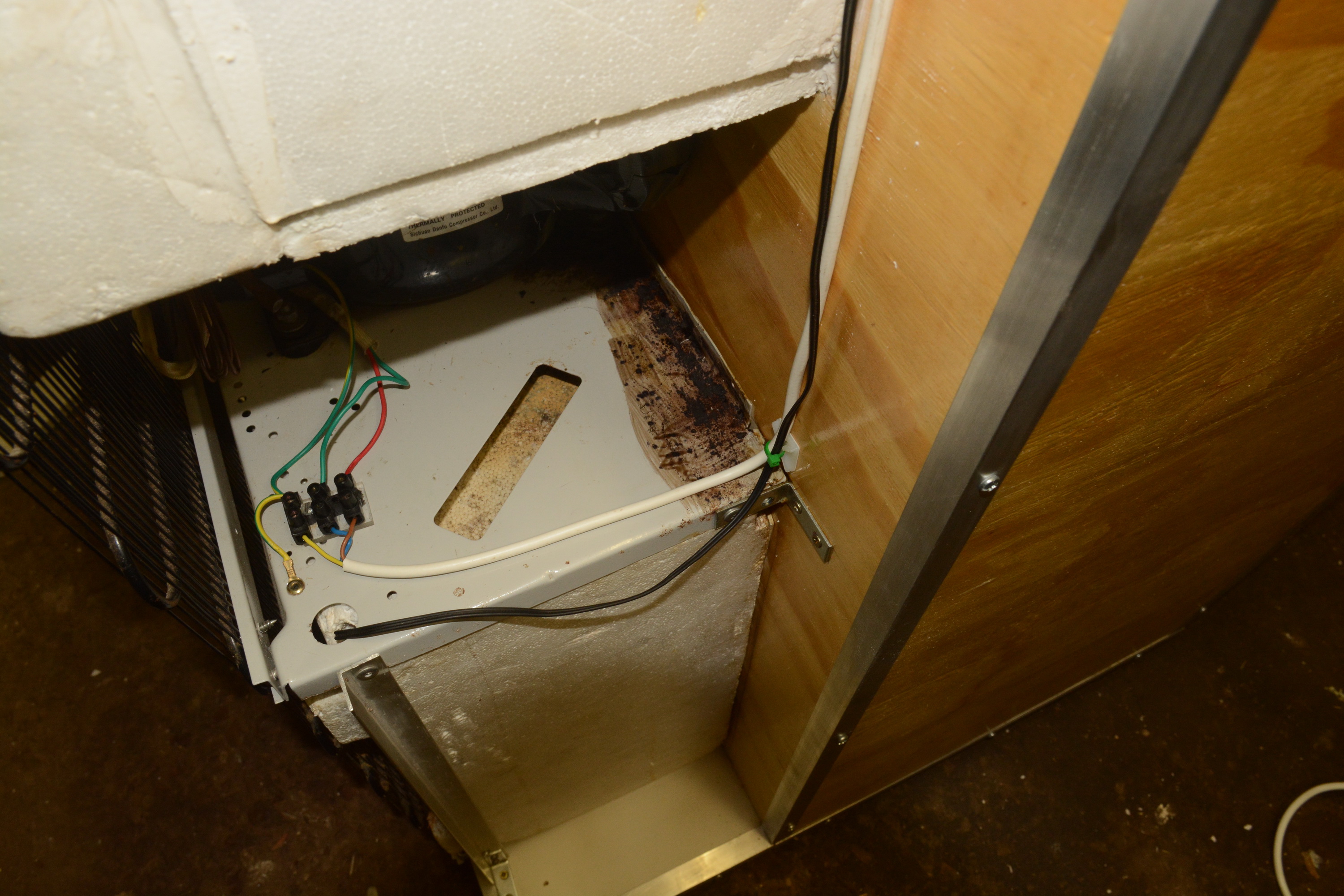
Photo 59 - The lower half of the wiring harness with the AC cable to the compressor and the temperature sensor cable.

upper_wiring_harness.jpg

Photo 60 - Upper wiring harness with the circulation fans (orange/yellow) and blower fans (red/black) circuits.

controller_finished.jpg

Photo 61 - The finished controller with all circuits connected.

controller_position.jpg

Photo 62 - The controller with the cover on and in position on the fermentation chamber.

The door latches are on their way from Amazon via snail, tortoise and plate tectonics, but that won't delay the first brew going into the chamber this coming week. Have to finish the mounting frame for the blower fans and decide whether to put side panels on the compressor section.

Almost done.
 

Latest posts

Back
Top