I'm back at it again !
After 7 successful brews, I decided to upgrade to a bigger case with more ventilation. The SSR got stuck on a couple of times and I rigged up some fans etc, but it was a mess. I'm midway through moving it to a recycled computer case, it's a thing of beauty.
The computer power supply has 220 input, and 12v and 5v outputs, just what I needed for the pump and pi.
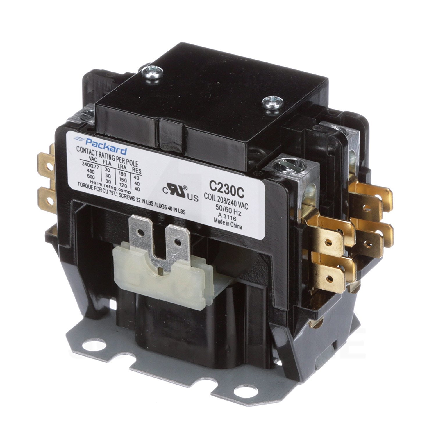
While I'm at it, I'm going to upgrade the Levitron switch with a Estop and contactor.
I can't seem to find a drawing with a 3 wire 220 and a contactor. ( I understand how the two hots run through the contactor)
Should the hot wire go to one side of the estop then to the side post of the contactor ?
Since there's no neutral, does ground go to the other side post of the contactor ?
Also, I was thinking of putting the contactor after the SSR, just to kill the element and leave the power on to the panel and computer.
Is that a bad idea ?
Thanks again for all your help !


![Craft A Brew - Safale BE-256 Yeast - Fermentis - Belgian Ale Dry Yeast - For Belgian & Strong Ales - Ingredients for Home Brewing - Beer Making Supplies - [3 Pack]](https://m.media-amazon.com/images/I/51bcKEwQmWL._SL500_.jpg)