• Please visit and share your knowledge at our sister communities:
  • If you have not, please join our official Homebrewing Facebook Group!

    Homebrewing Facebook Group

BruControl Uniflex v2: Adding Devices

Homebrew Talk

Help Support Homebrew Talk:

This site may earn a commission from merchant affiliate links, including eBay, Amazon, and others.
OK if the regulator has two grounds. Tie them together and to the central ground like you did. What is the digital input element reading?

Do you have a volt meter by chance? It would be good to measure the voltage at the pin to see if it is 3.0V in one state and 0V in the other (float switch triggered).
 
OK, finally got some time to get back to working on this. I had two problems.
  1. I had it wired backwards. In's should have been out and outs should have been in. Stupid mistake
  2. There were no instructions with the voltage device HiLetgo 2pcs LM2596 Adjustable DC-DC Step Down Buck Power Convert Module 4.0-40V Input to 1.25-37V Output with LED Voltmeter Display : Electronics. . After pressing the two buttons in different configurations, I figured out the interface. Or, at least I thought I did. A long press puts it into configuration mode. I assumed that meant you are setting the desired output voltage. You are not. After reading some of the comments on Amazon, I learned the buttons are just a calibration setting. The instructions are actually: a) read the voltage level coming out of the device b) use the buttons to match that voltage c) turn the set screw to get the voltage to where you want it.
If I had not made mistake #1 and then learned about mistake #2 before re-wiring it, I would have sent far greater than 3.3v to the uniflex, blown something out, and probably had to send the whole thing back for repair. Super lucky. If voltage reduction is a workaround that other Uniflex users may need, might be a good idea to put this warning in the Uniflex instructions.

Anyway, bottom line is that I got the float switch to work without blowing anything up. :ban:

Now, onto scripting and testing. Perhaps first brew next weekend.
 
I have a dual element uniflex v2. I am trying to understand the element controls and how the scripting relates to them. The workspace seems to have the interlock control that switches between ports 26 and 27. The PID then operates on Port 33 and will drive whichever port is selected through thte interlock control.
  1. For dual element setups, I see scripts using two PID devices. This would make sense so that they can each have a different input (temp probe) and output (element). But the output is controlled by the interlock. Do both PID's point at port 33? When I try to create a second PID, "PID Control Device" is not one of the options on port 33. But the existing PID is showing that as its type.
  2. Other people's scripts seem to be using a Duty Output device in addition to the PID devices. Why? Will these interact with the interlock in the same way. eg. they will do nothing unless their side of the interlock is on? Or, are these devices the "manual override" that the instructions say to watch out for?
Thx.
 
I noticed that in @BrunDog script he seems to have 3 devices to run his element. I know it is RIMS rather than HERMS, but should be same principle....I think.
"RIMS Heat PID" Enabled = false
"RIMS Heat Duty" Enabled = false
"RIMS High Power" Enabled = true

No idea what the "High Power" is doing differently than the Heat Duty at 100%.
 
Don't follow my script - my personal rig is different than the UF.

Yes, the interlock determines where power goes: to either one of two high power outputs (e.g. vessels). Set it where you want it (or off), then enable the controlling Device Element for it. If you want a PID (e.g. automatic control), then use a PID. If you want a Duty Cycle (e,g. manual control), then use a duty cycle. You can't create more than one type of Device Element on a given port. So if you wanted a PID for both, then use the same PID, and change its parameters in your script. Makes sense?
 
@BrunDog (or anyone else scripting with Uniflex), I am still struggling with three things related to the elements in my scripts
  1. I cannot see in the manual how (within a script) to flip the Element Interlock from #1 to #2.
  2. When I turn on a Heat Duty device coded to one of the ports that the Element Interlock is controlling, it disables the Element Interlock. How can I turn an element on full bore and still use the safety of the Element Interlock?
  3. Per @BrunDog previous post, I should use a single PID device to control the two elements and "change the input value" since only one can be on at a time. How do I change the input value? The instructions say 'Input Device' and that works through the device interface, but I am struggling with what the syntax is for the scripting. I tried all kinds of variations like "PID Control" InputDevice = "HLT Temp" and "PID Control" InputPortID = 201 but nothing seemed to work.
Thx for the help.
 
3. Try this. Substitute PID for the name of your device.

“PID” Enabled = True //enables element
“PID” Target = 150 //sets the target temp
“PID” Enabled = False //disables element
 
@swimIan, I appreciate the support. For #3, I am good with enabling and targeting.

So where I am
  • Enabling: understand from instructions, sample scripts, and your share
  • Target: understand from instructions, sample scripts, and your share
  • which element is going to fire in a "one PID, two element" system: question 1
  • which probe PID is going to compare to target in a "one PID, two element" system: question 3
eg.
  • Mash: use HERMS Output as the input value to raise up the HLT element to the Mash target temp
  • Boild: use BK probe as the input value to raise/keep BK element at a low rolling boil
 
Last edited:
“PID” InputPortID = X is what you need. You will have to determine which InputPortID is equivalent to your Herms or other temp probes.

For Boiling, I’d use a duty cycle element instead of a PID. A PID isn’t designed to boil very well.

//Boiling
“Boil element” DutyCycle = 100
wait “boil temp” value > 210
“Boil element” DutyCycle = 55
wait “boil timer” value < 0

Interlock (my best guess):
“element interlock” state = true //or false

The true would be one of the element and false is another. You might have to do some trial and error to determine.
 
1. The interlock element is a Digital Output. Use the ‘state’ property (set it true/false)

2. This is probably happening via the interlock safety script that is running in the background. I think you are stating it’s operation backwards though? We include it by default in the default configuration. It’s there to make sure the ielement is disabled before switching the interlock. This is good practice to ensure the relay doesn’t have to break the full current of the heating element.

3. Let me look at the manual myself and get back to you.
 
Thx @BrunDog and @swimIan #1 is now solved. The state = true vs. state = false is flipping it back and forth. I did not realize that Element Interlock was a digital output device....thought it was something unique that was separately coded by Pete.

For #2 I have setup a test script. I tried running it with the element interlock as true and as false. Same behaviour both ways. In first two seconds the HLT duty cycle device indicates it is on, but no heat coming from element because interlock is disabled. Next two secs Interlock turns on, but the HLT device is disabled. Final two secs BK device enables, but that disables the interlock so still no heat coming from anywhere. The only way that I can get heat in my system is by setting the interlock appropriately and enabling the single PID device.

// set everything to disabled to start from scratch
"PID Control" Enabled = false
"Element Interlock" Enabled = false
"HLT Heat Duty" Enabled = false
"BK Heat Duty" Enabled = false

sleep 2000
// try turning on the HLT element without the interlock
"BK Heat Duty" Enabled = false
"HLT Heat Duty" DutyCycle = 100
"HLT Heat Duty" Enabled = true

sleep 2000
// turn on the interlock and put it in one state or the other
"Element Interlock" Enabled = true
"Element Interlock" state = false // I also tried with true

sleep 2000
// try turning on the BK element
"HLT Heat Duty" Enabled = false
"BK Heat Duty" DutyCycle = 100
"BK Heat Duty" Enabled = true

wait "HLT Temp" Value > 150


For #3 the "PID" InputPortID = 200 does not seem to work. I also tried "200" and that did not work either. I tried that before my original posting because it it is listed as a property of the PID device. I also just tried "PID" InputPortID = "HLT Temp" PortID in case the string expected was some behind the scenes value. But, the term "PortID" also does not seem to be recognized by the execution engine. It is listed as "Port ID" in the manual. I tried both ways and the execution window threw an error on both.
 
I should also note that my Element Interlock is port 26 at true and port 27 at false. I have the "HLT Heat Duty" pointing to 26 and the "BK Heat Duty" pointing to 27. I believe that is the correct way to configure, but thought i should explicitly say it in case my assumption is incorrect.

I also turned off all other scripts while I was running my test script.
 
"PID" InputPortID = string (per BC manual pg. 87)

I would assume that string is the temp probe’s name. It looks like you tried this already but with quotes though. Make sure you are using the same spelling in the script as the temp probe’s name.

@BrunDog might know more how to work this out though.
 
Yes, "string" leaves room for a number of different options.

I have tried the device name: "HLT Temp" both in and out of quotes as well as the port ID: 200 both in and out of quotes. The device is a 1-wire analog input device that works fine in the scripting when accessing it as "HLT Temp" value.

Error when using "PID Control" InputPortID = "HLT Temp" is "object reference not set to an instance of an object"

The error is what made me think of trying "PID" InputPortID = "HLT Temp" PortID but that did not work either.
 
Last edited:
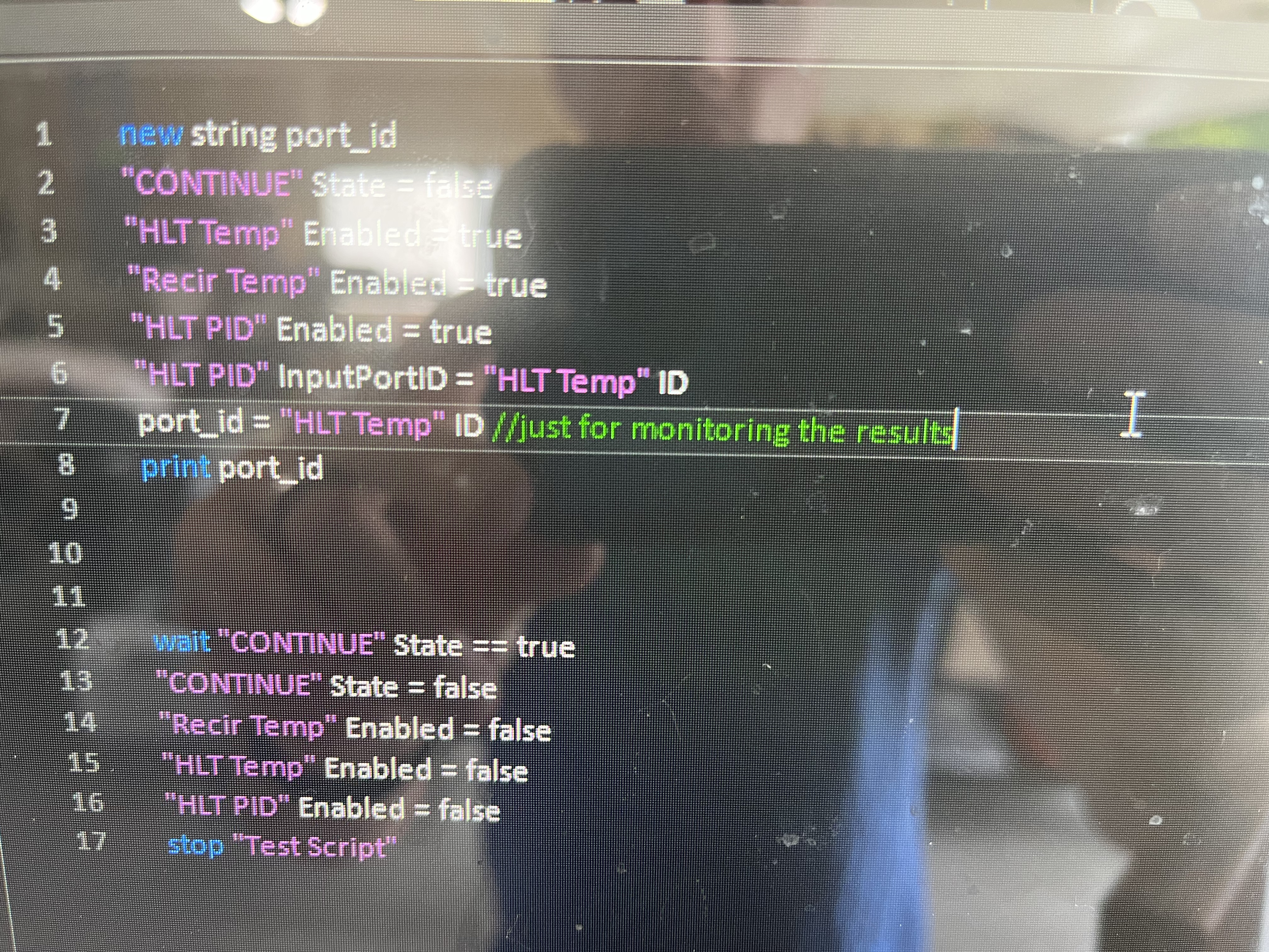
Did some testing. I think the pic will solve your problem.
A0F4387A-6691-4F7B-8117-05210FB326B6.jpeg
 
Sweet! @swimIan , you rock! Confirmed that works. Problem #3 solved. You have better creative troubleshooting skills than me, that is for sure.

@BrunDog it is definitely confusing that the naming of the Input calls for "InputPortID" while the value passed to it is just "ID" given that there is also a "PortID" parameter. A little note in the PID section of the scripting would probably be helpful to users.

Just problem #2 remaining now. Namely, how to get the Duty Cycle output to turn on the element rather than the PID

But, I can at least proceed with my script testing now that I can control the heat sources via the PID
 
Yes, you are correct - we need to document this in the manual. It is actually documented in the main BC thread, but that is not really helpful unless you specifically search for it!

I should also note that my Element Interlock is port 26 at true and port 27 at false. I have the "HLT Heat Duty" pointing to 26 and the "BK Heat Duty" pointing to 27. I believe that is the correct way to configure, but thought i should explicitly say it in case my assumption is incorrect.

I also turned off all other scripts while I was running my test script.
This isn't correct. The Digital Output has a "dual-throw" mode to simulate a dual-throw relay. It is associated with ports 26 and 27 as the two interlock relays. The dual-throw (with delay) mode ensure they are not both on at the same time.

Your heating modes (duty and/or PID) should not reference these relays - they should reference the SSR on port 33.
 
Your heating modes (duty and/or PID) should not reference these relays - they should reference the SSR on port 33.
Yessssss. That was the problem. #2 solved. I am fully back into script debug mode. Funny how you really need to think about simplification in order to test the script elements and then work back up to a more simulated dress rehearsal water brew once the scripts are mostly functional.

My system is set up to re-circ the mash through a sparge bar back into the mash tun. This is because there is only one inlet. It seems like I am losing a lot of heat with the water dripping through the air inside an uninsulated mashtun. Thinking I might switch to one of those sparge hoses with the links.
 
Hmmm, shouldn't lose a lot of heat here. If the lid is closed, the whole tun should be at a similar temp.
I put some metal bubble wrap around the MLT and the BK. Even if it is not helping much, I figured for $10 it would help to limit the heat in the garage in summer and may make a bigger difference in winter. Will probably pay for itself in saved electricity at some point. With the HERMS, HLT just requires too many cut outs to wrap: HERMS in, HERMS out, main in, main out, 2 handles, electric element, thermoprobe :)

Note: I have a hood fan above the BK (homemade from upside-down giant kitchen bowl and duct fan) and I box fan blow air in through the garage doors. Of course, I would wait until the heat of summer to finally get this system ready for prime time. :( #maryland
 
@BrunDog I just changed my plumbing configuration to allow for cooling during whirlpool. Had to add two more moto-ball valves maxing my uniflex out with 11 digital outputs. When I went into software to add the last one on port 0, it is not appearing in my list of available ports. Is it possible that I created a device at some point and it is invisible? I clicked the "eye" at the top of the screen and nothing appeared. I tried moving devices around to see if one was concealed and nothing seemed to be underneath.

I have clicked the "i" on each of my existing devices and confirmed none are on port 0. I have all the wires coming from my physical devices labelled with tape with the port number and none are labelled "0". Thoughts?
 
ruh-roh. I was hoping to use all the digital outs. Pin 17 indicates that it uses port 0.
 

Latest posts

Back
Top