BruControl: Brewery control & automation software

Homebrew Talk - Beer, Wine, Mead, & Cider Brewing Discussion Forum

Help Support Homebrew Talk - Beer, Wine, Mead, & Cider Brewing Discussion Forum:

This site may earn a commission from merchant affiliate links, including eBay, Amazon, and others.
I haven't tested myself, but seeing that Win 11 is the same SA release path that Win 10 is, I can't imagine there being any issues.
 
hi everyone, @BrunDog

first just to say this is the best software investment I did in 2020/21 and so far BC works great for me. I am a huge fan :cool:
May I ask if there is something I can do to further support future BC development @BrunDog please let me/us know how?

Q:
If I have only touchscreen tablet during the brew, some values I can change because there is a pop-up window called "KEYPAD". With it can just simply type in the numbers. But that keypad doesn't pop up for timer and for lookup tables elements. Is that something that could be implemented in next releases?

- timer values:
1633630098549.png

-calibration values and look up tables:

1633630164234.png


Until then. I am just thinking about bringing up windows screen keyboard… or running back to my main PC with keyboard. :)

thx
 
I apologize ahead of time I'm not sure what post/forum to put my question. I have finished documenting my control panel for how it is "currently" wired. I'm hoping there is some one that can help me with wanting to correct/change some things that the electrician that I had work on it (no longer available),
Do you guys have any suggestions where I can post the schematic and look to get some input?
 
1) Please bare with me as I am NOT an electrician. I am seeking help, knowledge, guidance for my current setup.
2) I had an electrician help me wire it and the current diagram is basically how it is currently wired. Please keep in mind the colors don't have much significance, except green is GND, black/red are for where they are on the bus bar or the receptacle I believe is correct, the Blue is Neutral/Common as I think its referred to. Due to life changes/events its taken me about 3 years to get back to this project.
3) After completing the current schematic (see attached) I have noticed that the relays for the the 2x Gas transformers are also connected to a receptacle 🔌 which they should NOT be, the receptacles should power on 2 pumps instead. The transformers are NOT wired at all. the switch for the gas is actually a "Latching Rotary Select Selector Switch - ON-NONE-OFF" intent was for manual override/safety.
4) I have recently verified that with the Brewpi software & the expansion boards to the relay boards all this works in software and does turn the relay on/activates it.
5) Currently I believe because the wiring for the gas is incorrect for my application/intent this is causing some sort of issue to where I do not have 120V out.
6) My hope or intent is to correct how it is currently wired for the gas, I can then wire the transformers into the relays, and provide an updated schematic after that has been corrected. I'm a very visual person so usually drawings or circle highlights etc. to point out what needs to be corrected is likely best way to go.
7) I'm sure there will be questions along the way, I will do my best to answer them to the best of my knowledge.

thank you in advance,
 

Attachments

  • Brew layout.pdf
    910.7 KB · Views: 44
cschmaltz80, I have a gas rig and found brewrigs.com to help me with the gas hookups. Maybe it will help you also. This is a standing pilot setup, but I find that to automate with BC, I might have to use something like a Honeywell Y8610U6006 to covert my honeywell VR8300A3500 gas valves. The price has doubled in the last year (like everything else) so it is on the wishlist.
 
This type of "pictogram" schematic, while apparently detailed, isn't the kind of technical document I'm personally comfortable commenting on... sorry about that. There may be others here who would. As it is a BrewPi control system I'd recommend posting it in their community to see if you can get some guidance there. I apologize for the redirect, as I did recommend you share it here - I just assumed it was a electrical schematic.
 
What inputs (temp?) and outputs (relays?) do you need?

Also, best is subjective. If you can be a little handy with a solder iron... check out the Olimex device noted above. ESP-32 based, with 2x relays built-in. Just needs wires attached for some 1-wire probes.
 
My apologies for posting this here--I tried the DIY thread, but no responses. Since this is for BC, I think it still fits within the parameters for posting here. I'm hoping someone here has something like what I want to do.

I am on the hunt for an enclosure that will house all the circuitry for BC. What kind of recommendations do you all have?

I've seen the basic Yuco enclosures in various sizes with a simple gland plate on the bottom, but hoping the community can point in the direction of other options.

Features I am looking for:
A modular back that could allow the standard 110V and 220V plugs along with thermistor plugs/wiring ports.
IP65 or IP66
Prefer SS, but open to all ideas (to include DIY options)

Thanks!
 
You can get WiFi interfaces but hard ethernet are better. You will need an single SSR and One Temp Probe to control a freezer and I would use the Hysteresis Element to Control the SSR. You may also need a programed delay if the freezer cycles to often (or just change the swing range so it just takes longer. You cannot have precise control of a compressor because "short cycling" will wear it out in short order.

I think I once read somewhere that 4 cycles an hour (one about every 15 minutes) was recommended for freezer. I found something on the internet that suggested 15 to 20 minutes or 2 to 3 times an hour). I put my probe in a water bottle that sits in a corner. Just drill a small hole in the lid and put the probe in the bottle (filled with water).

I think that my swing was 1 degree F. Might have been 2. No longer used so I am going from memory.

The most annoying thing about the freezer that I was using was that it had a Freeze Alarm that you could manually turn off, but was reset every cycle.
 
My apologies for posting this here--I tried the DIY thread, but no responses. Since this is for BC, I think it still fits within the parameters for posting here. I'm hoping someone here has something like what I want to do.

I am on the hunt for an enclosure that will house all the circuitry for BC. What kind of recommendations do you all have?

I've seen the basic Yuco enclosures in various sizes with a simple gland plate on the bottom, but hoping the community can point in the direction of other options.

Features I am looking for:
A modular back that could allow the standard 110V and 220V plugs along with thermistor plugs/wiring ports.
IP65 or IP66
Prefer SS, but open to all ideas (to include DIY options)

Thanks!
Hard to say because of what size is your Brewery. I personally have the room so I have sperate boxes for different things. I would generally say bigger is better if you have the room. Stainless will be harder to drill or punch). You can find some great deals on Ebay for open box at times.

I personally do not like Plastic boxes, but they are easy to drill.

Auber Instruments, Inc., Temperature control solutions for home and industry has some nice boxes and you can add a Heat Sink (and mount 3 SSRs to that One heat sink. I like Heat sinks to mount on DIN Rails for all my SSRs even if they do not need the Heat Sink.

Be careful of the Depth as well. You can find boxes that are too shallow. I like deeper boxes.

I have a single box that holds all the BC stuff (Interfaces, RTD Amplifier Platform, Analog Amplifier, etc. and wiring,

I have a Box for 220 SSRs, A different box for 110 SSRs and One Box for DC SSRs,

I also have a Box for Locking Push Button LED Switches (Illuminated Short Profile 22mm Pushbutton Maintained / Momentary [SW15] - $11.98 : Auber Instruments, Inc., Temperature control solutions for home and industry) after the SSR for my Pumps (Manual off if needed as they are normally controlled). As an added benefit, I know my pump is powered from the LED which I can see across a room. We have colored coded the Pumps, so I can have an untrained assistant brewer "Turn Off the Blue Pump" and he would push the Blue LED Button. We do this when we are filling our brew kettle with water for starting volume for example.

Also have some smaller boxes so I can manually control some valves if needed.


Size really comes down to how many things you are controlling, what type of control, where you can mount it, and aesthetics.
 
I just need to power the freezer 110V on and off and accurately monitor the temperature. Will the device connect to BC through my wireless network?

Yes. It includes a little box, wireless antenna, etc. The only thing needed is to wire in a 1-wire temp probe (or set of them) with a pull-up 2.2k resistor. This would need to be soldered, but its not a big deal if you have that basic skill.
 
I am on the hunt for an enclosure that will house all the circuitry for BC. What kind of recommendations do you all have?

I used a 3 compartment hanging tool cabinet for $75 at Harbor Freight. I have one compartment for high voltage, one for low voltage and one for the 24" touchscreen, mini PC and networking. You can see pictures in my prior posts in this thread. I built sub panels for each compartment and used the UniCon videos and schematic to build a 60 Amp dual element panel this 43 sensor ports, 4-100V AC plugs and 2-240V element plugs. Here is how it looks... https://www.homebrewtalk.com/attachments/localstormbrewing2-jpg.725188/
 
My apologies for posting this here--I tried the DIY thread, but no responses. Since this is for BC, I think it still fits within the parameters for posting here. I'm hoping someone here has something like what I want to do.

I am on the hunt for an enclosure that will house all the circuitry for BC. What kind of recommendations do you all have?

I've seen the basic Yuco enclosures in various sizes with a simple gland plate on the bottom, but hoping the community can point in the direction of other options.

Features I am looking for:
A modular back that could allow the standard 110V and 220V plugs along with thermistor plugs/wiring ports.
IP65 or IP66
Prefer SS, but open to all ideas (to include DIY options)

Thanks!

I'm not sure what you mean by modular back? A standard metal "box" enclosure will require you to cut holes to accommodate your pass-through items.

The enclosure and size (and therefore cost) are going to depend on your panel size. You will always need a bigger enclosure than you expect - also wiring into small enclosures is a PITA. Check out industrialoversupply.com for some decent units and pricing.
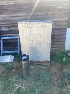
Bigger is better?
IMG_5289.jpg
IMG_5293.jpg

My brother just brought me this outdoor cabinet. It was used to house radio repeater equipment for a small police department and was just abandoned years ago.

May be too big but I am thinking of cleaning it up!

Waterproof!
 
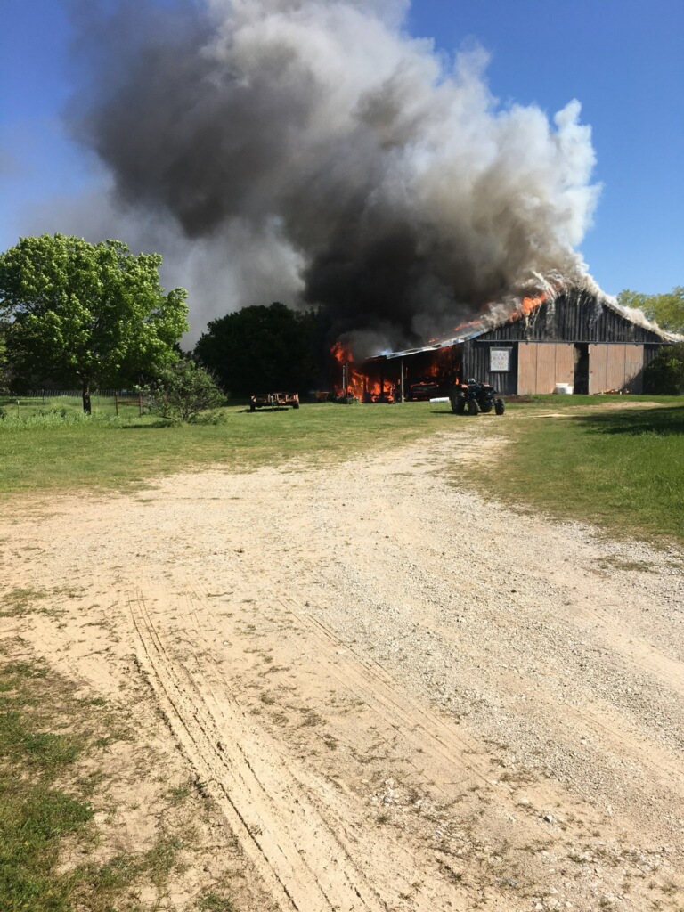
I had a full oak barn but only one section survived my fire.
barnfire.jpg


This panel is sitting right outside near where the brewery will be in a corner of my new barn (the green and white metal) in the pix above. I know we can make it nice with some elbow grease and paint. The question is leave outside or place inside if I use it. I am thinking of all my SSRs and Transformers in this big box outside and just have the interfaces inside in another wall mounted box.
 
if PumpOff == true //check if the pump has been turned off flag is set
if "Pump" Value >= 0:03:00 //if so, check to see if the Pump timer has passed 3 mins
"Pump" State = off //if so, turn the pump off
PumpOff = false //reset the pump has been turned off flag
endif
endif

I am going back to page 11 because I am trying to setup fermentation control with a glycol chiller, and heaters for two fermenters. I am just getting started, so I am sure I will have more questions, but here is the first: in this part of the script, is "Pump" value >=0:03:00 a typo? Is this supposed to be a separate pump timer element (with a different name), or do output elements also have timers associated with them? Sorry of this was already covered, but it takes a while to read a 168 pg thread.
 
Elements can’t have duplicate names, so yes it looks like a type. “Pump” can be a timer, so it can have a time ‘Value’ property. But it can’t also have a ‘State’ property. So one of these would need to be different, to reflect the actual name of the Timer and Digital Output elements they represent.
 
Elements can’t have duplicate names, so yes it looks like a type. “Pump” can be a timer, so it can have a time ‘Value’ property. But it can’t also have a ‘State’ property. So one of these would need to be different, to reflect the actual name of the Timer and Digital Output elements they represent.
Thanks, that is what I thought, but then I was starting to question it when I saw the script you posted earlier.

Another one: how would you do a delayed start on a glycol chiller (AC unit)? If I set it up as a hysteresis device, it will start automatically when cooling is called for, correct? What I would like to do is start the pump first, delay 10 secs and then turn on the chiller.
 
Turn on the pump, then wait 10 secs, then turn on the chiller. For example:

Code:
"Pump" enabled = true
"Pump" state = on
sleep 10000
"Chiller" enabled = true
OK, I think I am a little confused. If the chiller is setup as a hysteresis device, doesn't it need to be enabled to know when to turn on? I was thinking that I may need to use something else as my hysteresis device like a panel light and then check when it is on to start the pump and then chiller. Am I missing something?
 
Elements can’t have duplicate names, so yes it looks like a type. “Pump” can be a timer, so it can have a time ‘Value’ property. But it can’t also have a ‘State’ property. So one of these would need to be different, to reflect the actual name of the Timer and Digital Output elements they represent.
Since the new version has alias, I have started naming ALL of my elements in my own CamelCode.

I know by the name what it is and because of the naming convention, it will be unique naturally (although I have to make sure on things like timers). I actually went back and renamed every element I had.

for example I have a Main Timer on my Brewpage that I use for Mash and also for Boil, I just change the Alias between Mash and Boil as they are never on at the same time.

the name is "tmTopRight_B1"

tm tells me it is a Timer.
TopRight is it's name

_B1 tells me it is on my Brew Workspace 1.


I have a Temp Probe on the same workspace named:

MB_106_10KBrewKettle_B1

MB is my mega Main Brewery interface
_106_ is port 106
10K means it is a 10K NTC probe
BrewKettle tells me what it is
_B1 tells me it is on my Brew Workspace 1.

The Alias is Brew Kettle.

I have found this to be extremely helpful when I am looking for an Element as I stack them and also use the visible properties,

I never have to worry about duplicate names this way and can have two probes with the same Alias if I want. I find this very useful as I have colored pumps that I can put on different workspaces with the same Alias.

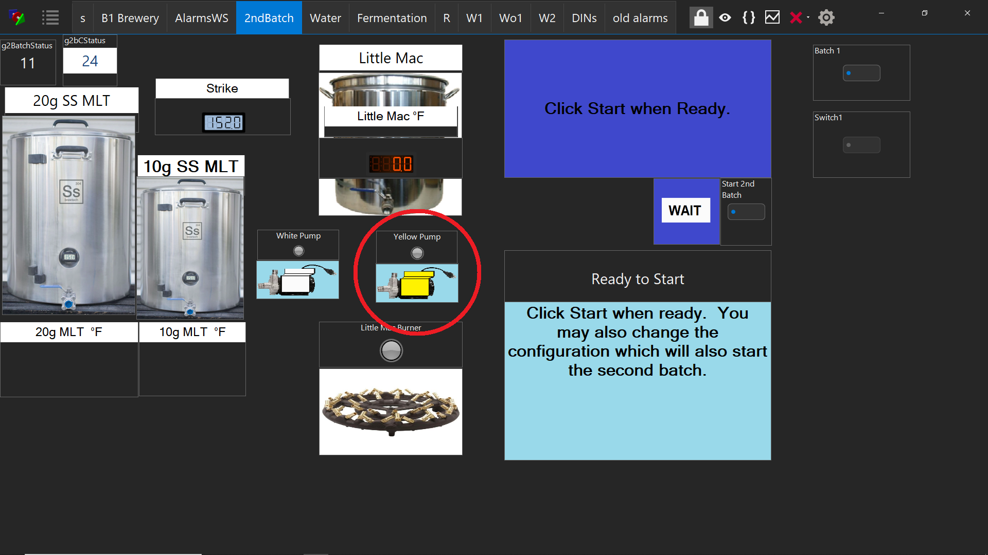
As an Example, I have a Yellow Pump (MNW_3_do_YellowPump_B1) on my Brewery Worksheet 1 (_B1) and one on my Second Batch Worksheet
(MNW_33_do_Yellow_Pump_2b).

MNW_3_do_YellowPump_B1:
MNW Mega Never Wired Interface
_3_ Port 3
do_ Digital Out
Yellow Pump (what it is)
_B1 tells me it is on my Brew Workspace 1.

MNW_33_do_Yellow_Pump_2b:
MNW Mega Never Wired Interface
_33_ Port 33
do_ Digital Out
Yellow_Pump (what it is)
_2b tells me it is on my 2nd Batch Workspace 1.
The Alias (Display Name) are all Yellow Pump


I have a house keeping script that allows me to control my true Yellow Pump Element ( MB_35_do_YellowPump_Wo1)

MB_35_do_YellowPump_Wo1:
MB is my mega Main Brewery interface
_35_ is port 35
do_ Digital Out
YellowPump (what it is)
_Wo1 tells me it is on my Wo1 Workspace (that I hide)

My Script:

//ScrYellowPump
//11/24/2020 19:19
//OakBarn Brewey
//Turn On MNW_3_do_YellowPump_B1
"MB_35_do_YellowPump_Wo1" state = true
"gblV_YellowPumpControl_WO1" value = 1
"MNW_33_DO_Yellow_Pump_2B" state = true
"gblS_yellowpumpix_B1" background = 2
"gblS_yellowpumpix_2B" background = 2
wait "MNW_3_do_YellowPump_B1" state == false
"MB_35_do_YellowPump_Wo1" state = true
"gblV_YellowPumpControl_WO1" value = 0
"MNW_33_DO_Yellow_Pump_2B" state = false
"gblS_yellowpumpix_B1" background = 1
"gblS_yellowpumpix_2B" background = 1
stop ScrYellowPump

You can see in the script I have some globals that I use for Pixs and the status of the Yellow Pump.

I can control my yellow pump on either workspace (or by script) and the displayed name of the Yellow Pump as well as the type (look and feel) of the Yellow Pump elements are exactly the same except for the unique name.
b1.png
2b.png
 
OK, I think I am a little confused. If the chiller is setup as a hysteresis device, doesn't it need to be enabled to know when to turn on? I was thinking that I may need to use something else as my hysteresis device like a panel light and then check when it is on to start the pump and then chiller. Am I missing something?
I’m sorry… I don’t know your application. I honestly didn’t go back to look at that script. I simply scripted what you mentioned above. As you can see, the Chiller is being enabled in my little script. That doesn’t mean it will turn on - if the temp target has been achieved, it will stay off until the temp falls out of the hysteresis zone.

That said, is you want a different function, it can indeed be scripted. For example, if you want the pump to run only when the chiller is on, we can do that. Please let me know the details of what you would like to do and I’ll try to help.
Thanks for the offer. I am comfortable writing the scripts, I just need to understand a little bit about what is under the hood on the elements. I have glycol reservoir with a pump and chiller that feeds two conical fermentors and I have 2-way valves on the fermentors to feed cooling coils. For heating I have heater tape around the fermentors. I would like to turn on the pump before turning on the chiller or opening the valves. So, if the glycol reservoir temperature gets above the hysteresis zone, turn on the pump, wait 10 seconds and then turn on the chiller. As far as I can tell, if the chiller is set up as a hysteresis device, it will turn on when the temp rises. That is why I was thinking I may need to use a panel light as the hysteresis device and then have a script check if the panel light is on and then start the pump, wait 10 secs and start the chiller. Unless you can set up a virtual hysteresis device to do a similar function.
 
Anything is possible. Question though... does it really matter if the pump turns on before the chiller? It will take more than 20 seconds for the chiller to really start to cool down anyway.

The reason I say is doing anything "before" is not possible, because only the hysteresis function has no predictive ability (ignore the setting by the same name for the sake of this discussion). It simply switches when the threshold is crossed, and basically instantly. So, you either make the pump the hysteresis device, then have the chiller turn on after it, or as you mentioned, use an un-used port to create a hysteresis device that tracks the temperature, then turn on the pump and chiller on/off afterward in time. The second option, if you feel is needed, lets you turn on the pump then the chiller, then when turning off, turn off the chiller, then the pump.
That is a good question I have been pondering. I am replacing an arduino based controller that I had coded before and this is how I set it up. The thought is you want to purge warm coolant and air from the system before opening the valves to the coils. The liquid in the reservoir is already cold, so this will fill all the tubing with cold coolant. One of the reasons I am upgrading is to add a rims to my mash tun. I would definitely want to turn the pump on before starting the rims heater to make sure any air is purged out. This is the same concept.
 
Our Glycol Chiller (Penguin) is independent of any other Element. In fact, it has it's own independent control of the cooling medium (glycol in the reservoir). The Glycol is set at it's target independent of BruControl. When we did have a DIY Cooler, we used the same principal. The Glycol was set at a temperature regardless of any demand. As with any Glycol system, you need the reservoir to act as an accumulator for your line glycol. We never found that we needed any heat as the fermentation is exothermic.

You can also insulate your tubing which has the added benefit of it not dripping condensation.

We keep the Glycol around 40 F for Ales and 28 F for Lagers but have done Ales with the Glycol at 28 F as well if we have two different types going.


from Penguin Manual:

Glycol Mix Ratio: If operating at 28F (brewing) it is most common to use 40%-50% glycol to water, this ensures that the glycol does not freeze. The cooling coils will be up to 20F cooler than the liquid bath temp, so keep this in mind when choosing what ratio to use if you plan on operating at a different temperature.


Temperature (for brewers): One of the most common set points for brewing is 28F, hence why glycol chillers are rated at this temperature. We would discourage you from setting it lower than this for brewing applications, colder is not always better. If set too cold, beer will freeze to your cooling coils and the ice acts as an insulator preventing proper heat transfer to the coils. We commonly see this problem when the chiller is set around 24F -25F, but occasionally 28F is still problematic depending on the alcohol content of the batch. If the glycol bath is at the set temperature but your batch has stalled out on cooling in the low to mid 40's, freezing is likely the issue. If you are having this issue try a set point of 32F-34F and walk it down a degree at a time
 
A Hysteresis Element does not have any external State or On/Off that you can control except if the device is Enabled. Once enabled, the internal state (On/Off) is regulated by the Element itself. You have some control via the Target of the Input, "on Offset" (the swing), as well as a "On Delay" that can help with short cycling.

One caveat using a Hysteresis Element is that it's Input Element (Temp Probe) must also be Enabled. If you set the input TempProbe enabled property to false, it will also set the Hysteresis Element enabled property to false.

A Glycol Chiller (or any compressor based equipment) should be controlled by a Hysteresis Element.

If you had an "On Offset" or 4 and a Target of 28, your Chiller Hysteresis Element (enabled) would "turn on" the compressor at 32 and continue to be on until the Target was reached (28). Your Chiller Hysteresis Element (enabled) would "turn off" the compressor until the Glycol reached 32, then it would go though it cycle again. You do not need to control the temperature of the Glycol finely as 32 0r 28 Glycol will chill your Brew. You just leave your Glycol Enabled as long as you are fermenting. You use the Pumps to Control the Fermentaion Temperature, not the Temp of the Glycol (as long as it is lower than your fermentaion Temperature.
 
Any downside to using a panel light as the hysteresis device? My understanding is that the hysteresis device will continue operating when the host computer is disconnected. In this case, I don't think that matters, because I need the chiller, pump and valves to all work and that requires a script which requires connection to the computer. For the heating side, I have Flexwatt tape and will set this up as the hysteresis device and it should work without connection. Is this correct?
 
Are there any guides or tips on Windows settings to make sure you do not have inadvertent disconnects of the computer? I pulled out an old laptop for this purpose and while I was setting up the workspace it randomly rebooted to install an update. I would like to prevent this or other disruptions that could ruin my fermentation from happening automatically.
 
Back
Top