BruControl: Brewery control & automation software

Homebrew Talk - Beer, Wine, Mead, & Cider Brewing Discussion Forum

Help Support Homebrew Talk - Beer, Wine, Mead, & Cider Brewing Discussion Forum:

This site may earn a commission from merchant affiliate links, including eBay, Amazon, and others.
What wiring is CR05? Two inputs? I’d be careful assuming this wiring is universal... I’ve seen different schematics claiming to be CR05.
With the UniShield @oakbarn, assuming you can afford the outputs, you can use two outputs to drive one valve, then use the “dual throw” function of the primary output. It will mimic a DT relay. Or just use a DT relay as mentioned as @crane mentioned.
 
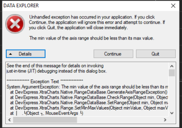
I found a bug with the Data Explorer that may or may not have already been noted. If you attempt a box zoom and pull the box outside the extents of the DE window, you get an Unhandled Exception. You can hit Continue and keep working, and everything seems to work fine, so its likely just a nuisance error.
 
I found a bug with the Data Explorer that may or may not have already been noted. If you attempt a box zoom and pull the box outside the extents of the DE window, you get an Unhandled Exception. You can hit Continue and keep working, and everything seems to work fine, so its likely just a nuisance error.

Hmmm... I wasn't able to duplicate this. You are experiencing this on build 19?
 
Hmmm... I wasn't able to duplicate this. You are experiencing this on build 19?

Yep, build 19 - I'll email you the contents... maybe it'll shed more light.

1618846181592.png
 
Weird, If I drag center to the left or bottom and release outside the DE window, I don't get the error, but if I drag center to top or right I do. I'll get a video when I get back to my main desktop.
 
What wiring is CR05? Two inputs? I’d be careful assuming this wiring is universal... I’ve seen different schematics claiming to be CR05.
With the UniShield @oakbarn, assuming you can afford the outputs, you can use two outputs to drive one valve, then use the “dual throw” function of the primary output. It will mimic a DT relay. Or just use a DT relay as mentioned as @crane mentioned.
CR05 has five wires.

There is are two wires to control the open and close that are reversed polarity to open and close the valve. That is why it is somewhat confusing and the need for another DPDT relay or an H Bridge.

The other three wires are for indicator signals. A GND and an Open Signal and a Closed Signal. I am building a small display panel for my manifold that will show the valve position. In addition, I have 110v LEDs connected to each Pump Circuit that will be on when my pump is on. I know that the Workspace can also show this, but this display panel will also work when I am doing something manually. I plan to add rotary switches so I can have total manual control as well as Auto with BruControl.

I have found that I need manual control of a Pump even on Auto so I have a Push Button LED Switch in series after the SSR for each Pump. When Priming a Pump, they work very well. In addition, when the Pump starts to cavitate when the vessel is empty, I can quickly turn off the pump manually.

I have also found that If I fill a vessel through a Pump that is OFF, I have a lot less cavitation and priming issues.
 
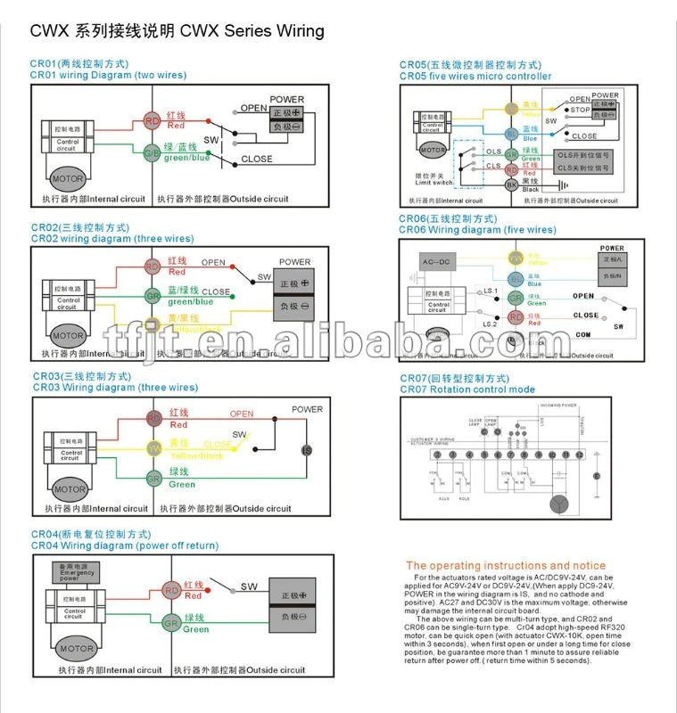
Sorry, I should have asked for a schematic. Assuming the below is accurate, you will need a DPDT relay for CR01 and CR05. You can use two outputs and the "dual throw" function in BruControl for CR02 and CR06 as long as you have high current drivers (eg MOSFETs or the UniShield). For CR03, you only need one output and you may be able to get away with triggering it without any high current driver, meaning directly from the interface assuming the trigger voltage matches your interface AND the current required is low, like <=15mA. For CR04, like CR02/06 you can drive it with one output via high current drivers. Hope that sheds light.

1618925002140.png
 
Sorry, I should have asked for a schematic. Assuming the below is accurate, you will need a DPDT relay for CR01 and CR05. You can use two outputs and the "dual throw" function in BruControl for CR02 and CR06 as long as you have high current drivers (eg MOSFETs or the UniShield). For CR03, you only need one output and you may be able to get away with triggering it without any high current driver, meaning directly from the interface assuming the trigger voltage matches your interface AND the current required is low, like <=15mA. For CR04, like CR02/06 you can drive it with one output via high current drivers. Hope that sheds light.

View attachment 726407
I will be using CR05. I want LEDs to be beside the valve letting me know the physical status of the valves. I have toyed with the idea of a large sheet of white aluminum with the manifold and pumps as LEDs. I can do both the LEDs near the valves and on the big sheet. I already have Push Button Maintained LED Switches in the Pump Circuit with additional lights already. While I plan on a Large Screen for BruControl, you cannot see things from across a space. We generally sit and watch the brew across the brewery.
 
Physical controls? Oh the humanity! But hey... it's your brewery! Kidding of course.

I think TeamViewer supports multiple monitors, or alternatively a wireless HDMI / splitter can help duplicate screens in multiple places if you wanted.
 
Physical controls? Oh the humanity! But hey... it's your brewery! Kidding of course.

I think TeamViewer supports multiple monitors, or alternatively a wireless HDMI / splitter can help duplicate screens in multiple places if you wanted.
I did the HDMI Splitter and multiple monitors when I was a BCS brewery. I still had the Pump Manual Control. I had rewired it once to be totally Auto but reverted back so that I could cut off a Pump if I needed to (which we found necessary often enough for the reversion). I also have issues with burners that needed a kill switch. The monitors are not big enough from our cigar bench to see details. I only had a couple of electric valves and had manual control override when I needed. These were for my tap water and real handy when cleaning. I also found Manual Control Override good when I messed up the Auto Process( i.e. troubleshooting a script) as I hate practice with water. When implementing, We will brew a batch of beer! My physical parts have started to arrive!
 
Hi brewers,

We posted build 20 of the "1.2 beta/ RC". This includes three updates:

  1. Fix for the bug in Data Explorer posted by @RiverCityBrewer brewer above.
  2. Adds the ability to specify a number of pixels that an element must be moved by before it actually moves. This is designed to help prevent elements from moving when opening their properties by touchscreen users. Go to Settings -> Environment -> Minimum Move Threshold to adjust. I'd suggest a threshold of about double your grid size.
  3. Adds a format dialog for Date and Time variables to address display of these, per @exoticatom above.
    1. For Globals, we added a field to control these formats right in their properties dialog. For local variables, we added a 'Format' property. These utilize special template characters. For example:
Code:
new time t
new string s

t Format = "hh:mm:ss:fff"
s = t

or

Code:
new time d
new string s

t Format = "MMMM dd, yyyy"
s = t

Template characters for above are:
  • h = single or double digit hours (1-12), hh = double digit hours, zero padded (01-12)
  • m = single or double digit minutes (1-59), mm = double digit minutes (01-59
  • s = single or double digit seconds (0-59), ss = double digit seconds (00-59)
  • f = tenths of seconds (0-9), ff = hundredths of seconds (0-99), fff = milliseconds (0-999). Up to 7 fff’s supported.
  • All other characters print directly to the output (e.g. “Time = hh” would print “Time = 01” at one hour).
  • To print any of the special characters directly, escape with a backslash, for example: “hh\h” would print “01h” at one hour
  • M = single or double digit month number (1-12), MM = double digit month number (01-12), MMM = abbreviated month name, MMMM = full month name
  • d = single or double digit day number (1-31), dd = double digit day number (01-31)
  • yy = double digit year, yyy = full year, yyyy = full year
  • tt = AM or PM

Please let me know if you have any questions, concerns, or issues. Still working on getting the other items in 1.2 wrapped up!
Thank you so much. Works as described.
Globals format was really really nice touch!
 
One thing I would like is a switch on any Element to NOT be in the Data Exchange, I use lots of globals and have some that will never be used for data. For example, I have some that just display some text like "Add Bitter Hops!" or a picture.
 
Looking for a little guidance running my first script. I set up my fermentation chamber with hysteresis elements for heat and the fridge, both reading off a 1-wire temp. Also have a global element, "Set_Temp" for a setpoint. The problem I'm running into is that while the script can enable the heat and fridge elements, they are turning on/off according to the hysteresis temp plugged into the elements themselves and not the global element temp, per the script. Any suggestions? Here's the script:
[start]
"Beer_Temp" Enabled = true // enables fermenter temp sensor device
"Fridge" Enabled = true // enables fermenter cooling hysteresis device
"Heat" Enabled = true // enables fermenter heating hysteresis device
"Set_Temp" Enabled = true // enables temperature setting global element
new value High_Temp // creates a new variable named High_Temp
new value Low_Temp // creates a new variable named Low_Temp

[loop]
High_Temp = "Set_Temp" Value + 1 // sets high temp trigger as setpoint + 1 deg
Low_Temp = "Set_Temp" Value - 1 // sets low temp trigger as setpoint - 1 deg
if "Beer_Temp" Value > High_Temp
"Fridge" Value = on
else
"Fridge" Value = off
endif
if "Beer_Temp" Value < Low_Temp
"Heat" Value = off
else
"Heat" Value = on
endif
goto "loop"
 
You have "Fridge" Value = on or off, but this is not valid as you can't set this. In other words, you can read it but not write it. It is determined by the interface based on this Hysteresis Device Element's properties (settings). I think you mean to enable either the cooling or heating hysteresis devices. Remember that when you enable one, you probably want to disable the other one. I'd also add a time delay before the goto, else the script will execute repeatedly very quickly, which is not necessary.

All that said, I don't think you need to enable or disable these elements. Since you are creating a deadband in between them (assuming the offsets prevent them from overlapping), you can just leave them enabled and eliminate all the if/endif statements you have. Just leave the High_Temp and Low_Temp in the loop. Also, I would recommend adding a check to make sure the Set_Temp has changed before changing the Hysteresis device temps. LMK if you would like an example.
 
Looking for a little guidance running my first script. I set up my fermentation chamber with hysteresis elements for heat and the fridge, both reading off a 1-wire temp. Also have a global element, "Set_Temp" for a setpoint. The problem I'm running into is that while the script can enable the heat and fridge elements, they are turning on/off according to the hysteresis temp plugged into the elements themselves and not the global element temp, per the script. Any suggestions? Here's the script:
[start]
"Beer_Temp" Enabled = true // enables fermenter temp sensor device
"Fridge" Enabled = true // enables fermenter cooling hysteresis device
"Heat" Enabled = true // enables fermenter heating hysteresis device
"Set_Temp" Enabled = true // enables temperature setting global element
new value High_Temp // creates a new variable named High_Temp
new value Low_Temp // creates a new variable named Low_Temp

[loop]
High_Temp = "Set_Temp" Value + 1 // sets high temp trigger as setpoint + 1 deg
Low_Temp = "Set_Temp" Value - 1 // sets low temp trigger as setpoint - 1 deg
if "Beer_Temp" Value > High_Temp
"Fridge" Value = on
else
"Fridge" Value = off
endif
if "Beer_Temp" Value < Low_Temp
"Heat" Value = off
else
"Heat" Value = on
endif
goto "loop"

I think this would work:
As @BrunDog said, you cannot use on/off with a hysteresis device. They have no state property, only the enabled property for On/Off.

[start]
Beer_Temp" Enabled = true
"Set_Temp" Enabled = true // enables temperature setting global element
new value High_Temp // creates a new variable named High_Temp
new value Low_Temp // creates a new variable named Low_Temp

[loop]
High_Temp = "Set_Temp" Value + 1 // sets high temp trigger as setpoint + 1 deg
Low_Temp = "Set_Temp" Value - 1 // sets low temp trigger as setpoint - 1 deg
if "Beer_Temp" Value > High_Temp
"Fridge" Enabled = true
"Heat" Enabled = false
else
"Fridge" Enabled = false
endif
if "Beer_Temp" Value < Low_Temp
"Fridge" Enabled = false
"Heat" Enabled = true
else
"Heat" Enabled = false
endif
goto "loop"

I had this in it as well but I do not think you need it:

if "Beer_Temp" Value < High_Temp
if "Beer_Temp" Value > Low_Temp
"Heat" Enabled = false
"Fridge" Enabled = false
endif
endif

Generally, your compressor device (Fridge) should not cycle less than 12 minutes apart as a general rule of thumb for short cycling. It is hard to find a good definition of "short cycle" in terms of minutes as to what a short cycle is, but 5 times in an hour (60/5=12) is the lowest number I have seen. Some suggest 4 times for a 15 minutes period between cycles. You should time your cycles and add some delay if needed. The time for a short cycle may be in the manual for the fridge.
This is helpful, thanks! So if I understand this conceptually, the fridge element temperature should be set below the range of my fermentation profile, and have the heat set above the range. The script activates the elements for cool/heat as needed based on the high_temp/low_temp. I change the set_temp global element manually and the script reads that and adjusts. I think where I went wrong was i was incorrect in thinking the script would overwrite the hysteresis settings.
 
Lot's of ways to skin the cat... Here's how I would do it. As I mentioned, I don't see any reason to enable and disable the heating and cooling hysteresis devices... the will operate in parallel and not overlap (e.g. the cooling one will reduce the temp down to the High_Temp and then turn off and the heating one will increase the temp up to the Low_Temp and then turn off).

Note the '"Set_Temp" Enabled = true' line was removed as you don't need to enable a global

Code:
[start]
"Beer_Temp" Enabled = true      // enables fermenter temp sensor device
"Fridge" Enabled = true      // enables fermenter cooling hysteresis device
"Heat" Enabled = true      // enables fermenter heating hysteresis device
new value High_Temp      // creates a new variable named High_Temp
new value Low_Temp      // creates a new variable named Low_Temp
new value Old_Temp     // creates a new variable to hold the previous Set Temp
Old_Temp = "Set Temp" Value       // sets the previous Set Temp to the actual Set Temp

[loop]
wait Old_Temp != "Set Temp" Value
High_Temp = "Set_Temp" Value + 1      // sets high temp trigger as setpoint + 1 deg
Low_Temp = "Set_Temp" Value - 1      // sets low temp trigger as setpoint - 1 deg
"Fridge" Target = High_Temp      // sets the cooling hyesteresis device temp to the upper deadband edge
"Heat" Target = Low_Temp      // sets the heating hyesteresis device temp to the lower deadband edge
Old_Temp = "Set Temp" Value       // sets the previous Set Temp to the actual Set Temp
goto "loop"
 
Last edited:
I went more along the lines of oakbarn's script. I added in a 300000ms sleep at the end and that seems to at least work for now to prevent the fridge from short-cycling. Even though this isn't a complicated script, I have to say it's pretty cool. Ready in time to brew up a saison tomorrow. Phew!
 
Hello, is not optoisolated relay board can cause problems to 1 -wire temp sensors? I have been struggling to make the sensors work stable, but they disconnects once in couple minutes showing -127 C, I changed topology from star to linear then stubs and they still disconnect. Change sensors for dallas chips , still the same. So iam thinking relay board i have doesnt have optoisolation and this could be a problem? I read a while ago that you plan to put a "reject" option to eliminate spikes and errors, are this going to be implemented any time soon? This could be an solution for me, before i invest any more for rtd sensors and amplifier boards.
Regards
 
Will need many more details to debug this (interface, communication type, power supply, # sensors, etc, etc.). Schematics and/or pictures are a big help. Most problems like these are power-supply and/or noise related. Isolating items to determine what introduces the problem is a helpful practice. Are you seeing the d/c's randomly or during other events (like when activating the relays)?

We can add the internal rejection but its better to fix your issues as good software can't remedy failing hardware.
 
Interface is mega board usb connected to windows tablet. Sensors i used before were waterproof i bought from china, i changed them to original dallas chips, didnt help. Power sources are 12 v for mega, 5 v for sensors, 24 v for some sensors, all din mounted. 4 12 v solenoid valves with flyback diodes for fermenters. I put lately emi filters before 5v and 12 v supply, no difference. When tried 4 sensors at home without any other stuff connected it was working stable. Problem started when i hook it up toghether. I supected vfd for noise but when i disconnected it was not any better. Sensors are connected linear with cat5 cable.
Tomorrow i will try change relay board for optoisolated kind i have ordered, and i am thinking about disconecting it all and start from scratch.
 
I'm sorry but its just not enough detail to venture a specific guess. Schematic or pictures, part numbers (links), etc. is the only honest way to identify a specific problem. You can use the MEGA's 5V for the 1-wire sensors. Make sure all grounds are tied together back to one point. Try tying DC ground to AC earth. Try with one 1-wire sensor, then keep adding them. Keep the wires short, and if possible, use shielded cable or grounded for them. Try a pull-up of 2.2k instead of 4.7k. Disconnect all other devices, then start adding them back in to see when the problem starts to occur. Leave all other ports disabled with hardware attached, then try enabling in turn to see if the problem starts to occur.
 
Hello, is not optoisolated relay board can cause problems to 1 -wire temp sensors? I have been struggling to make the sensors work stable, but they disconnects once in couple minutes showing -127 C, I changed topology from star to linear then stubs and they still disconnect. Change sensors for dallas chips , still the same. So iam thinking relay board i have doesnt have optoisolation and this could be a problem? I read a while ago that you plan to put a "reject" option to eliminate spikes and errors, are this going to be implemented any time soon? This could be an solution for me, before i invest any more for rtd sensors and amplifier boards.
Regards

How many 1-wires are you running? What value pull-up resistor are you using? Does the -127C come up after some of them start to sense/read higher temperatures? I have 5 1-wires and was seeing this (-196.6 F, but same thing) happen using the on-board 4.7k ohm resistor for my unishield. Switching to a 2k worked at room temp until I started testing and a few of the sensors were exposed to higher temps, which then bricked out (i.e. read 196.6 F) the readings for all 5 sensors. Progressively trying lowered valued resistors until it didn't happen sorted things out.
 
I will need 8 sensors, but im testing with 2 of them for the fermentors. First i was using 4,7k resistor, but changed that for 2,2k. Readings are wrong just after start of sensing. I under estimated the size of control box and bought 16in x 16in which is little bit tight so its packed that i suspect some interferance. I wil try to rewire some just to check all connections are good, maybe put an vfd and power supplies in second cabinet to separate them .
By lowering a resistor value you mean lowering from 4,7k and go down? What values i should buy and try?
 
The difference between 4.7k and 2.2k aren't all that significant... 2.2k is needed on 3.3V busses, but I kinda like it better for 5V too. Anyway, this should not be the target for your solution. How long are the wires? If they are not shielded, I suggest you use shielded wire (grounded back at panel only). Do you have a schematic or pictures of the setup you can share?

There is an odd timing issue with the MEGA and many (~5+) 1-wire sensors we've seen when connecting the MEGA via USB... I'd suggest switching to a network connection in that circumstance.
 
Hi, i dont have schematics for my build, i used ones from website. Now i have whole box disconnected and i am trying to rewire all , it looks like spaghettis inside. I will rewire DC grounds as you sugested.Ordered some new terminals for connections also for better look. As a USB connection i have Basic license , didnt plan to use a network. I will upgrade probably but first i would like to rewire all and check if didnt mess something.
 
A friend of mine has a fantastic setup for his BruControl. He is having trouble with his proportional valves. He bought two of these valves:
https://www.aliexpress.com/item/330...earchweb0_0,searchweb201602_,searchweb201603_
He bought the 0-5v version. They come with five wires and he hooked the 12V+ up to his 12v rail in his cabinet, GND from valve to GND rail in cabinet(which is in turn routed to the Mega on his board(he has one of the official brucontrol boards). The green wire(PWM) to a digital output set to Pwm on his rail. He says he has it connected to port 3 on Bank 9 on his board.

Now when he attempts to control the valve proportionally, 0 (off) and 100(on) works but anything in between causes the valve to switch a bit back and forth instead of just staying put in one place. He has a flowmeter and the flow changes between 0 - 2.87 liters per minute, so there are quite a bit of fluctuation....

What could this come from?
What should he check?
I made him made sure all devices were correctly set up in BC and it seems so.
 
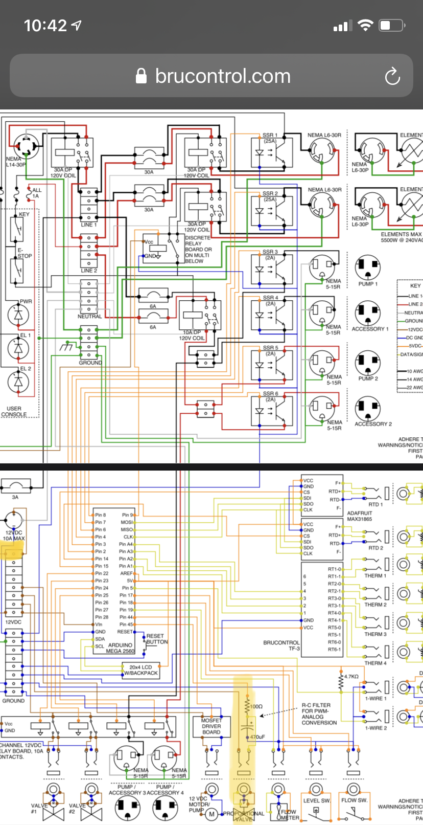
Your friend needs to convert the PWM signal to analog voltage. Brucontrol carries a amplifier board but an RC circuit would work too.

someone else already replied as I typed.

Would something as simple as this work? Mosfet-modul IRF520 for Arduino - Moduler
It's a simple mosfet. If he would hook 5V from the Arduino up to the VIN port, and V+ outport to pump then use the Arduino pwm signal to set it halfway open? If at 50% pwm from arduino it would send 2.5V stable to the valve?
 
Hi... I think I'm chatting with him via email, but will add comments here for posterity.

First, you can't connect an output via the UniShield into a proportional device which requires an analog voltage. As mentioned above, that signal is PWM, not analog. If you connect from the P pin of an output, it simply won't work for this reason, but if you connect a D pin, that voltage will be the voltage of that bank on the UniShield... so it could be 12V or 24V, which will likely damage the input of the valve, since it is expecting nothing more than 5V.

You can use the analog amplifier mentioned above, or you can use single channel PWM -> Analog converters, such as Amazon.com: KNACRO PWM-to-Voltage Module 0% -100% PWM Converted to 0-5V 0-10V Voltage Analog to Digital: Home Audio & Theater
 
TLDR: tangentially related BruControl question-- I need help with proportional SSRs.

I am looking to build my 50a, 4 element, Mega2560 BruControl panel for my brewery over the course of the next month but...

I have two 4.5kw elements that will touch wort and I want to utilize proportional ssrs for each of those elements to mitigate any potential thermal induced stress or sensory detractions in my finished beers.

That said, I am looking at these Crydom Proportional SSR

However I do not know which one to order-- I want to control them via voltage control, using a PWM out for each element, run through their own PWM-Voltage converter modules.

Can you proportionally control only one leg of a 240vac and in effect proportionally control the entire output of the element?

If so, should I get an SSR that is rated as if it is seeing 120v or 240v. I ask because, the output voltage offerings of the SSRs above are either 48-140vac or 180-280vac.

I've only ever used on/off SSRs in the past, and the output of those have always been like 24-240vac.

Thanks for the help/clarification!
 
Whasup @cyberbackpacker! One of the OG’s!

Yes, you can use Proportional SSRs for your build. We think they are a great option to reduce heat cycling on the element as long as you can handle the $. I recommend the MCPC series. For example, use one MCPC2425A for 0-5V control to control each element. Therefore, you would need two of these OR use a MCPC2450A to power both elements in parallel (I'd spring for the 90A version for the headroom myself, but your call as long as your heatsink is beefy).

Yes, you will need a converter to change the 5V PWM from the MEGA into 0-5V or 0-10V analog for the SSR. We have the Analog Amplifier board which has 4 channels and will do it for you, or you can get single channel models on Amazon, etc., like the one I posted right above your post.

Once the SSRs are installed, use a PWM Output for manual control and the “Use PWM” switch in PID’s for proportional output there.
 
Back
Top