• Please visit and share your knowledge at our sister communities:
  • If you have not, please join our official Homebrewing Facebook Group!

    Homebrewing Facebook Group

BruControl: Brewery control & automation software

Homebrew Talk

Help Support Homebrew Talk:

This site may earn a commission from merchant affiliate links, including eBay, Amazon, and others.
OK, one last question for (for the moment). I see a number of things to potentially address this concern but I suspect there are some ways that are better than others. The problem I am having is that I have a 3.3v PWM signal coming from the Grand Central controller going to the BruControl AA-1 board as I need a true analog output for speed control of some pumps, etc. Perhaps as expected (I am not sure), I can no longer get the AA-1 board to deliver a 0-5V signal output from the 3.3V PWM input signal. I get 3V max output with 5V connected to the AA-1 VCC, and a 4V max if 12V is connected to the AA-1 VCC (24V makes no difference). Is there a good way to rectify this problem?

I’ll need to look over the schematic of the AA-1 and it’s op-amp and get back to you.
 
@VacationLand... I just realized a problem with SAMD micros that will prevent them from passing through an initialization on the I2C bus, effectively stalling or delaying the FW from entering into normal operation. That init looks for an LCD display on pins 20/21, and with nothing attached there gets hung. So, please use 2.2k or similar resistors to pull those pins up to 3.3V.

This problem happens with the Feather as well and is a well documented problem. The pull-ups should resolve the stalled boot problem, but as far as the oddities above with those pins, I’m not sure what the solutions are until I test it myself. I do appreciate you forging the path though!!

I'll see what I have and give it a go at some point. I do need to sleep tonight...it has been a few days :).

Why not throw another odd ball out there! I uploaded the serial firmware and that went well. BC said it was connected but the communication window would stop showing data coming over after 5-10 seconds and the whole BC program would freeze and eventually I had to kill it the task manager. It happened three times in a row, so I deleted the serial controller in BC and just removed the GC from my enclosure. I will do the rest of my testing on the GC at the bench at this point and put the Robotdyn MEGA 2560 back in so stuff works again and I can talk over Ethernet.
 
Last edited:
Wow that’s odd. I didn’t have any troubles with either but certainly didn’t run the tests you did.

I wouldn’t be surprised if the GC has some hardware issues... the first one I got have the oscillator soldered upside down. I had a heck of a time debugging as it wasn’t totally dead.

I’ll try to debug it.
 
For a Counter Element you have the following read only properties in scripting:

value
RawValue

Rate
RawRate

What is the difference with RawData and its use?
 
Doing some testing on the GC, now with the pull up resistors on 20 & 21. Firmware install and network setup is super smooth with no issues. Termite gets a response back from the board quickly and everything works like it should. For network setup after the firmware install, I did not need to enter bootloader mode again by double pressing the reset button. The pull up resistors also prevents the weird connection, disconnect, stall, then reconnect routine. Connections are fast and it remains steady. I have also tested the PWM pins again and it is working a bit more like the wiring diagram.

Now pin 9 sends out a PWM signal. I also confirmed that 13, 14, and pin 15 do as well. 8, 11, 45 and 48 still do not. My Analog A4 and A5 still kill communications with BC if a 3.3V signal is hooked up to it or a ground at boot up, so either that is just a thing that needs addressing in some fashion (firmware or physically) or some of this is just that I have a busted board (perhaps I broke it). I will test some more...
 
Last edited:
I noticed on the Adafruit website that the GC analog pins are also digital I/O. Is this unique to the GC and is that a potential area that is creating the weird problems I am having with A4 and A5 (actually A2 is weird as well)? The thing is, A2, A4, and A5 do all function properly as an analog input but they all prevent communications with BC at start up if they are connected at start up. Boot up and then connect A2, A4, and A5 and they all work normally. That is so puzzling to me. It is still possible that my GC is just damaged in some manner of course.

"A2 through A15 - These are each analog input as well as digital I/O pins"
 
I don’t think so. The SAMD21 in the M0 based boards has this capability too and we have enabled the pins to do either. We didn’t enable that overlap on the GC yet, so I don’t think this is related to the anomalies you are seeing.

We’ll test it but it may take a few days to get to it.
 
I’ll need to look over the schematic of the AA-1 and it’s op-amp and get back to you.

Sorry BrunDog. Bone headed thing on my end. I had to change the PWM pins for the pumps feeding the AA-1 as they were not putting out PWM. I forgot that the values were "Raw" and when I put in 100, it was not all the way on. 255 is needed in this case of course. I pop in 255 and I get 5.0V out with the 3.3V PWM input from the GC. So false alarm. Sorry about that.

I'm slowly getting the GC to work, even if the pins that don't work for me stay unused. I barely have enough analog inputs with the few that are basically acting odd. So far, I have just left them unused.
 
I am about to change over my "Radiator" on the BCS system. It is controlled as PID in the BCS. It has a standard optocoupler SSR (cheap Amazon Variety).

Do I need to get a better SSR (I actually have one that is supposedly PWM capable) and hook up to a true PWM Port on the Mega, or just use a Digital I/O and leave the cheapo SSR. The tolerance of even up to a degree is acceptable although if I command 155.2 (The BCS holds that), that is what I seek. I use the Radiator as a Hot Water Bath for a modified HERMS System (A CHILLZILLA with Hot Water On the Outside Tube and WORT on the Inner Tube.)
 
Also curious what the recommended and default settings for calc time and out time on the PID element. Mine are currently 5 and 5...
 
Just wanting confirmation that this Jaycar ESP32 product is compatible with BruControl. And confirmation that the Adafruit 4*20 LCD + backpack will work like Mega R3's?

And is this the component that supports the Tilt devices?

And while I am at it, is this Jaycar ESP8266 compatible with BruControl? Their site is not completely clear whether this "main board" is all that is required, or does it still require an Arduino to plug this board into.

Also thought I'd let any Aussie compatriots that the JayCar "DuinoTech" Mega R3 and ethernet module devices are working with BruControl. Bit cheaper than purchasing the official Arduino stuff, and more importantly in stock all the time.
 
Hey BrunDog. I'm looking for an opinion on the fitness on my GC micro that I have been struggling with. I have most things ironed out but my analog inputs are a bizarre mess. While I have previously stated I had enough analog inputs "working" if I simply ignored the ones that oddly killed communication with BC if they were connected, I had not yet tried to get any useful data out of the analog inputs that were not causing that odd communication error. I tried that today and basically none of them work correctly. Mind you, other than altering the output of some current to voltage converts to output 0-3.3V and implementing some voltage dividers to deal with a few 5V sensors, the setup is the same as the MEGA 2560 setup that was working a few days ago. I have confirmed all the voltages are as they should be at the GC screw shield input pin for a variety of the sensors I have and the micro doesn't track (read) the signal either at all or correctly. More odd is the fact that A3 reads 0 volts when there is actually 3.3V at the pin until another analog is connected to A2. Then it reads but incorrectly. Pull the analog signal from the A3 pin and the A3 input in BC still reads a value that is close to the value it read when the pin was actually seeing voltage. So stop a pump, the flow stops, flow meter local display properly says so, the analog output drops at the GC pin but it still reads a fluctuating value.

I didn't mention this specifically before but if I use A2 on my micro, it trips the breaker to a my 12V (I think) power supply since the first time I powered it up. Like something about A2 was shorted. I can't see anything physically wrong however.

I am just checking to be sure there is nothing in the wiring map/BC firmware that could be causing this. Otherwise this micro looks to be toast. Unfortunately they are out of stock so I had to order one without headers and I have no solder those on to install in my panel to see if the micro is indeed toast.
 
That’s crazy. I can’t imagine any input having enough ability to cause a 12V feed to trip.

I only personally tested pin A1 and it worked normally. I can’t speak to the others but I’d suggest you wait until I try to duplicate your findings. This will not happen until the end of the week as only I have the GC and I can’t access it this week.

IIRC, you have the Arduino IDE. If you install the GC code base, you should be able to run some analog input test examples to see if the results are the same.

I never was able to figure out what exactly was happening as I just wanted it to stop and found it was A2 that was making everything go haywire on power up.

Indeed, I could give that a go in the IDE as well. I will see if I can fit that in.
 
That schematic is missing the relays. Which brings me to the next test. Disconnect the valves from the relays and cycle the relays via BruControl. Any noise then? What about manually cycling the valves by jumping wires to their switch signal as if you were the relay (take the relay out)?

Let’s take this offline so we don’t clog up this thread. Pls email us. We can then come back here to report the solution.

Thanks to a bunch of help from BrunDog, I've now got my 5 metre PT100 probes installed for my client and everything is working.

Firstly I'll say that there was never a problem with BruControl, it was all to do with the hardware install.

Secondly, this was never BrunDog's problem, but he put a lot of time into helping me out when it was never his responsibility.

So the solution ended up being purchasing shielded PT100 temp probes, and then earthing out the shield to the Arduino. We also tied the negatives of the 9V circuit (Arduinos) and 24V feed (ball valve control, etc) together. The transformer for the 24V circuit was tied to incoming earth, so as far as I can tell this is the single point earthing recommended.

There is obviously quite a lot of interference being generated by the 24V side of the hardware, so I view shielded PT100 cable as a work-around as the temp probes are now working correctly. But obviously the noise is still being generated so I will need to deal with that to actually reduce noise generated so it doesn't affect other devices in the future.

Once again, a big thank-you to BrunDog (and others who commented to help out) for getting this solution in place.
 
Some string operations would be nice in the scripting engine.
In my case I am passing a ferment name into BruControl via the API.
This name is then displayed on the fermentation workspace in BruControl and also on a LCD on the actual fermentor.

If the name is longer than 20 characters, it would cause the text to wrap on the LCD and then my nice display would be all screwy.

A "truncate string to 20 characters" function would be nice. I haven't really had the need for other string functions yet (position of character in string, , split on character, etc)

I'll code it up now to do it via the API and pass through "FullName" and "FullNameRestrictedto20Characters" values. Just a passing thought you might like to add to the suggestion list. Or not... :-D
 
Alright, I am doing some testing of my GC with wonky analog readings in BC. I pulled it from the enclosure and it is being tested bare on the bench with an analog voltage/current generator and I was hoping some folks out there with more experience than me could give me some direction. I created a simple Arduino sketch to read an analog pin every 2 seconds and print it to serial. I started with a MEGA 2560 to get my bearings and the pins read the voltage and tracked as expected. The Mega ADC has 1024 voltage divisions, so doing the math to get voltage from the raw step reading on the pin is as expected. The weird stuff came about with the Grand Central. It is supposed to have 4096 voltage divisions and as it is a 3.3V logic micro with an internally tied AREF, I expected to see 4096 as the raw reading at 3.3V but rather the serial monitor is telling me the raw value is 1024. I am still learning Arduino coding but am I missing something or is something amiss with the GC? In this scenario, if I ignore this aspect, the board appears to be working appropriately with analog inputs. I need to test it on the bench with BC firmware and then test it again in place in the enclosure with the screw and ethernet shield.
 
Last edited:
For 4096 (12 bit values), you need to declare it using analogResolution. I wouldn’t worry about that - just make sure the basic functions are working across all the analog pins.

OK, I get it. I simply added that bit to my sketch to keep the result clean but after testing A0-A4, the GC is no longer being recognized so I cannot communicate to it to get readings. Unless it is in bootloader mode, it is not seen as a Com port. I can load sketches and BC firmware in bootloader mode but it is "dead" once in the normal mode (I do have pins 20 & 21 pulled up via 2.2k resistors as before). I have tried various cables and computers. No idea what is wrong now but the board is silent unless it is in bootloader mode. Man this powerful little board is being a PIA!

Regardless of that, the analog values for A0-A4 were reading correctly when the micro was talking but now the micro is a bit of a brick.

The Sunfounder MEGA 2560 in the same setup, works as expected on all analog inputs (A0-A15). That being said, I find it odd that on the MEGA, if I pull the AREF wire that is tying it to 5V, the analog reading remains the same and accurate. If AREF was not tied internally on the MEGA 2560, wouldn't pulling the 5V from the AREF change the readings? Using 3.3V makes no difference on the analog pin readings either if it is hooked up to AREF.
 
Last edited:
Is there a way to reference historical data in BC other than from a trend graph? If not, could it be considered for a future release?

My use case is monitoring fermentation rate at multiple time intervals. I can certainly script it, but its not pretty (or really reusable).
 
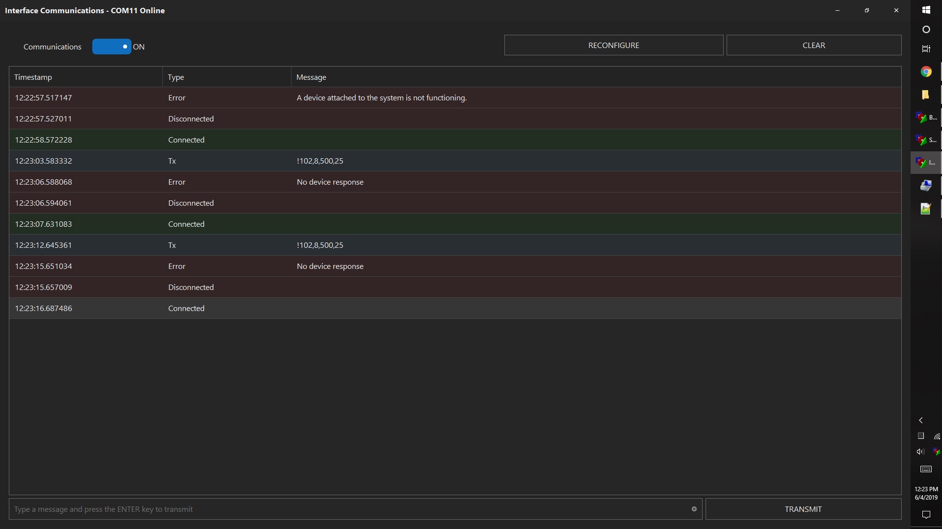
I received my new Grand Central (headerless) and it indeed acts like a properly functioning micro should. Testing via an Arduino sketch shows that all the analog pins are working properly. I can flash the BC firmware to it with no problem as well but serial communication to BC is spotty, at least in my setup (the MEGA does work as expected however). It will swing between online and offline and when online, the errors below show up. One refresh of data, then no device response, then it will pop back up again give one refresh of data, then no response again. This has occurred with two different USB cables. The board is still headerless so I cannot test ethernet easily yet.

I have tested with and without the 2.2k pull-up resistors connected to 3.3V on pins 20 & 21 with no differences in connectivity stability. This is all with the V45 S Grand Central firmware and recommended 115200 baud rate.

GC Serial Error.jpg
 
Last edited:
is there any reason for the range of the duty cycle to be limited to 10000 (10 seconds) at the upper range? I run some fans and would like it longer. I know I can do it with scripts. Just wondering why the limitation.
 
Just wanting confirmation that this Jaycar ESP32 product is compatible with BruControl. And confirmation that the Adafruit 4*20 LCD + backpack will work like Mega R3's?

And is this the component that supports the Tilt devices?

Just purchased the Jaycar DuinoTech ESP32 development board and installed the firmware. All went well with firmware install and network config. BruControl can see the new interface I created, but I won't have time to actually test anything else until tonight. Will probably configure this to control my keezer and report temps up to my website.

So looks like the Jaycar DuinoTech range of arduino-clone hardware appears to work with BruControl. That's good news because the official Arduino stuff is expensive here, and for some reason no-one stocks the Arduino ethernet cards. So I end up buying from OS and taking a massive hit on shipping.....
 
Is there a way to reference historical data in BC other than from a trend graph? If not, could it be considered for a future release?

My use case is monitoring fermentation rate at multiple time intervals. I can certainly script it, but its not pretty (or really reusable).

The data is in the log files - you can pull that out and use it how you like so long as you read-only it.
 
is there any reason for the range of the duty cycle to be limited to 10000 (10 seconds) at the upper range? I run some fans and would like it longer. I know I can do it with scripts. Just wondering why the limitation.

No, it was an arbitrary number. As you said, anything bigger could be scripted. We can bump it up to 30 seconds.
 
The data is in the log files - you can pull that out and use it how you like so long as you read-only it.
OK, thanks... another can of worms opened! I have some Globals that are writing to the data log around 16x a second and some that only write a few times a day (none of which I believe I am controlling). The one generating the largest file (over 50MB/day) runs in a script that only updates every 10 minutes, so I'm rather confused as to why it is logging so frequently. Is there a way to control that?
 
I'm not sure if this is a bug or by design, but Globals (and possibly Inspectors) only seem to log data when they are on the currently open workspace tab. Even if the Global is updated via a script running, but not in the active workspace, it will not log any data until I open that tab. When that tab is open, on my system anyway, it logs at 16/sec.
 
Another Adafruit Grand Central M4 update. I had previously confirmed that all analog inputs were working properly on the new board I received (via the Arduino IDE) so I soldered on the headers and tested the board with BC v45 E firmware. While the serial connection is not working with BC, an ethernet connection via a Seeed Studio 5500 ethernet shield is working. It connects fine and is stable. Focusing on the analog inputs I have confirmed that A0-A7 inputs work in BC and they report very accurate values. The problem is that analog inputs A8-A15 are currently not functioning at all with BC firmware v45 E (these pins are fine however and confirmed to work). They report 0 no matter the signal input of any connection at all (they should float like the rest but they don't). It appears the Grand Central BC firmware is not setting up everything correctly for the Grand Central micro and if you need more than eight analog inputs, you should not consider the Grand Central for BC just yet.

I also reconfirmed that the GC today will not output PWM from many of the pins indicated in the wiring map. I thought those might be due to my previous bad GC micro but it appears to be related to firmware or the board documentation from Adafruit is simply incorrect.
 
Back
Top