BruControl: Brewery control & automation software

Homebrew Talk - Beer, Wine, Mead, & Cider Brewing Discussion Forum

Help Support Homebrew Talk - Beer, Wine, Mead, & Cider Brewing Discussion Forum:

This site may earn a commission from merchant affiliate links, including eBay, Amazon, and others.
OK, couldn't wait. Risked making blatant changes to the ESP32 wiring map - hope it doesn't catch anybody off guard. Updated the application (only the ESP32 definition file in that package has changed), the Interface Wiring Map, and the Firmware (to 45B for the ESP32 only).

To be clear: Pin/Port 2 can no longer be a counter, but 4 can be. Then 15 - 18 can be counters as well - total of 8. LMK how it goes!
 
Are there potentially some errors in the beta Grand Central wiring map?

"D = Digital Input or Digital Output (Note: Input can be 5V active high or low, output is 5V). * indicates Digital Output only"

Is the GC tolerant of 5V on the input if it is digital and does it really output 5V?


"A = Analog Input (Note: range is compared to AREF, which is tied to 3.3V… also 3.3V is maximum input)
...
Analog Reference pin (AREF) should be tied to +5V or less to measure analog voltage inputs"

So should the AREF be tied to 3.3V or 5V and what is meant by "is tied to 3.3V" (is the GC AREF already internally tied to 3.3V from the internal regulator or is it still required to do this on a shield for example?). If the analog inputs are limited to 3.3V, wouldn't tying the AREF to 5V produce issues with the analog readings and potentially damage the GC?
 
Last edited:
Yes... good pick up! Not sure how these got left in there. The GC is NOT TOLERANT of anything 5V! We'll correct this ASAP.

The AREF on the GC is currently internally tied unless you cut a jumper on the board, so we will leave this language in the map. I don't know any reason to not use the same 3.3V VCC source as the micro, but someone might want to reference it to 1.0V (and pickup a lot of junk in the process).

Edit: Fixed it. Please refresh your browser cache if it doesn't download updated.
 
Had a strange problem with my script last night. It picks up a target temperature from a global variable (which is populated via the API from my website) and sets the Target for a Hysteresis element.

My script was

Code:
if "BlackFridge_NewTargetTemp" Value == -50
        // do nothing
        //"BlackFridge_NewTargetTemp" Value = "BlackFridge_TargetTemp" Value
elseif "BlackFridge_NewTargetTemp" Value != "BlackFridge_TargetTemp" Value
        "BlackFridge Control" Target = "BlackFridge_NewTargetTemp" Value
endif

This resulted in the SSR the element controls very briefly flicking on and off. Sometime this would push power through to my fridge and then straight off again. Pretty damaging for a compressor if left to run over a few days and flicking on and off very few seconds.

I updated my script to below, which has corrected the brief flicking in all cases except where I push through a new target value. Given this will only be every few days, I can live with that. Might be nice to include the same value check inside the Hysteresis element so nothing happens if the value being set equals the existing target.

Code:
if "BlackFridge_NewTargetTemp" Value == -50
        // do nothing
        //"BlackFridge_NewTargetTemp" Value = "BlackFridge_TargetTemp" Value
elseif "BlackFridge_NewTargetTemp" Value != "BlackFridge_TargetTemp" Value
        if "BlackFridge Control" Target != "BlackFridge_NewTargetTemp" Value
            "BlackFridge Control" Target = "BlackFridge_NewTargetTemp" Value
        endif
endif

Updated script to include the if section, which I didn't think was important to the problem.
 
Last edited:
I had thought about using something like an LT1635 op-amp + reference chip to generate a stable reference voltage for the AREF pin rather than using the supply (still might). Then I could use one of the inputs as a monitor for what VCC (and other power rails) is doing. If VCC is tied to AREF then you can't actually read VCC proportional things.

I imagine most people wouldn't bother with that though.
 
FYI, we updated our UniShield options to include an expansion I/O board for the Feather UniShield. This will allow for an additional 16 I/O per shield. Link: https://brucontrol.com/buy/hardware - model FED-1 at bottom of page. These can be stacked on top of the UniShield or placed side by side.

I recognize a UniShield plus an expansion I/O is an expensive proposition. We're making these in small volumes, so economies of scale aren't in place yet. That said, it will allow direct powering of lots of devices, which would save on additional hardware and wiring headaches.
 
ESP32 Flow Meter Update: I tried all eight of the counter inputs in the new FW rev and confirmed that they were working fine using the flow meters I listed above. I used a 27K resistor to GND as the divider (with the top resistor being the 10k pull up in the flow sensor). All of the counters behaved as expected. I then hooked 4 of them up together to a single sensor (GPIO4, 15, 16, 17) and gave them a bunch of input pulses to make sure they all got the same counts (they did).

I did notice one small thing, all the rates were the same except for GPIO15's output. It was significantly different for short bursts of pulses from the sensor. I assume this was just a timing thing and how that particular counter was getting polled. For continuous flow, it read the same steady state value as the others.

Thanks again!
 
OK I can see that. But sorta like the Name Property. It is self evident on the Element itself. What would be a potential use for that property in a Script?
 
I see that you can set a Digital Output to an Active Low. Can someone provide me with a circuit on how to control an SSR with an Active Low Output?

And also a reason to do so. I see that it is provided so assuming it is useful.

I really do not quite understand the Active Low.
 
OK I can see that. But sorta like the Name Property. It is self evident on the Element itself. What would be a potential use for that property in a Script?
For instance, if you wanted to copy the element display value of "62 F" to a Global on another workspace.
 
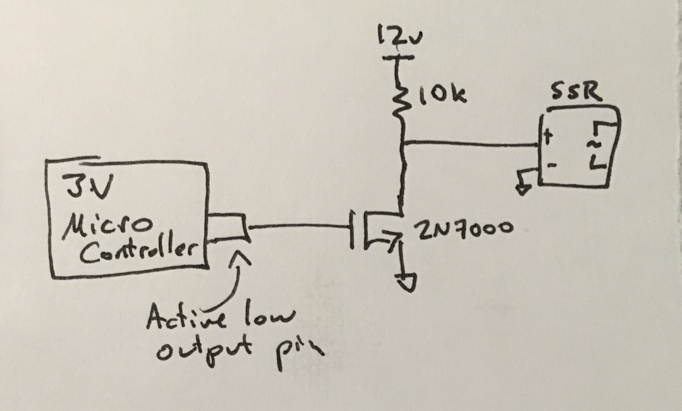
One reason might be if you were using a 3V micro controller (ESP32, Grand Central, etc) and the SSR you have didn't reliably turn on for a 3V input. In that case you might need a level shifting circuit up to a higher voltage. That could be done with a transistor and a resistor, however that introduces an inversion in the signal. By using an "Active Low" output (digital 1 = 0V, digital 0 = 3V) you add in an inversion to compensate for that.

Below is a diagram doing that (I had to do this once on a cheapo SSR that didn't work for <4V in or so). When the pin goes low the input to the SSR goes high (12V) and turns on.

IMG_0858.jpg


I don't know if it also changes the output character on the micro. It might make it a strong pull down with a resistive pull up (like in the active low input case).

Also, the 1/2/4/8 relay boards that are broadly available take active low signals so all of my outputs that talk to those are set to be active low.
 
Last edited:
Low active is about the relay boards; all of the versions I've used/seen are active low.
SSRs are in a different realm and conventionally are wired for high active...

Cheers!
 
I've been trying to get my new Grand Central board (MEGA 2560 replacement) installed and it has been a struggle. Everything worked perfectly with the MEGA 2560 and I have been careful with the few 5V sensors (I disconnected them all I think). It shouldn't be so problematic but some oddities on some analog inputs (connect anything to pin 102 and it won't establish communications with BC over ethernet), same goes for digital input 43, and PWM that doesn't seem to be working on some of the pins given in the BC wiring diagram. Not sure where to go from here but PWM is not functioning on Pin #8, #9, and #45 on my board. Basically the AA-1 board I am feeding the PWM signal to outputs nothing when connected to these pins. All the other PWM listed on the wiring diagram do work however. The GC also has an odd boot-up connection behavior where it will connect to BC for one cycle, then disconnect for 30 seconds and then reconnects.
 
For instance, if you wanted to copy the element display value of "62 F" to a Global on another workspace.[/QUOTE

Thanks. So if there is a Calibration Dialog and you can add prefixes or suffixes, you can get them with the value as well. I did try it with a Counter Input and you get the Primary Value only (with its prefix and suffix).
 
Yes, this is the risk of new hardware... not everything is perfectly understood or documented. We only get the info from the pinout page: https://learn.adafruit.com/adafruit-grand-central/pinouts

When you say "can't connect anything"... does that mean a grounded signal? 3.3V signal?

With the "odd boot up" up describe, how are you connecting (serial/ethernet/wifi)?
 
Low active is about the relay boards; all of the versions I've used/seen are active low.
SSRs are in a different realm and conventionally are wired for high active...

Cheers!
I have a Relay board that is Active Low and now I can use it! I thought you might need some additional circuits. This is almost a "Duh" moment.
 
One reason might be if you were using a 3V micro controller (ESP32, Grand Central, etc) and the SSR you have didn't reliably turn on for a 3V input. In that case you might need a level shifting circuit up to a higher voltage. That could be done with a transistor and a resistor, however that introduces an inversion in the signal. By using an "Active Low" output (digital 1 = 0V, digital 0 = 3V) you add in an inversion to compensate for that.

Below is a diagram doing that (I had to do this once on a cheapo SSR that didn't work for <4V in or so). When the pin goes low the input to the SSR goes high (12V) and turns on.

View attachment 629071

I don't know if it also changes the output character on the micro. It might make it a strong pull down with a resistive pull up (like in the active low input case).

Also, the 1/2/4/8 relay boards that are broadly available take active low signals so all of my outputs that talk to those are set to be active low.
Thanks. This was another piece of the puzzle.
 
Yes, this is the risk of new hardware... not everything is perfectly understood or documented. We only get the info from the pinout page: https://learn.adafruit.com/adafruit-grand-central/pinouts

When you say "can't connect anything"... does that mean a grounded signal? 3.3V signal?

With the "odd boot up" up describe, how are you connecting (serial/ethernet/wifi)?

Indeed, new hardware and it is a risk. I did examine the pinouts and for example, PWM should be available on all the pins you have set in the BC wiring diagram but still some don't function. I do need to confirm if DO works on these to perhaps confirm if the pins are simply bad in some physical way.

Yes, by "can't connect anything", I mean I can't connect an 3.3v signal that works on another pin to one of these suspect pins (with both elements setup identically in BC) or even a grounded signal. The board will boot up fine in this scenario and I can ping it fine as well but BC won't connect. Pull the wire from the suspect pins, reboot the GC, and BC will connect to the board just fine. I should add that I am using the MEGA 2560 screw shield and while I couldn't identify a problem with that, perhaps there is?

It was late when I wrote that post, so I should be clear that I can't get BC to connect ever when the suspect pins are connected to an input (wire) but pull those and BC will connect to the board for one cycle and then after another 30 seconds or so, BC connects back to the board for good. So the board boots up, BC sees it, the comm window in then says the board disconnected and after the delay, it is connects again. I have no idea what is causing that our where the problem lies in this chain or even if this is a problem beyond just being annoying.
 
Last edited:
One reason might be if you were using a 3V micro controller (ESP32, Grand Central, etc) and the SSR you have didn't reliably turn on for a 3V input. In that case you might need a level shifting circuit up to a higher voltage. That could be done with a transistor and a resistor, however that introduces an inversion in the signal. By using an "Active Low" output (digital 1 = 0V, digital 0 = 3V) you add in an inversion to compensate for that.

Below is a diagram doing that (I had to do this once on a cheapo SSR that didn't work for <4V in or so). When the pin goes low the input to the SSR goes high (12V) and turns on.

View attachment 629071

I don't know if it also changes the output character on the micro. It might make it a strong pull down with a resistive pull up (like in the active low input case).

Also, the 1/2/4/8 relay boards that are broadly available take active low signals so all of my outputs that talk to those are set to be active low.
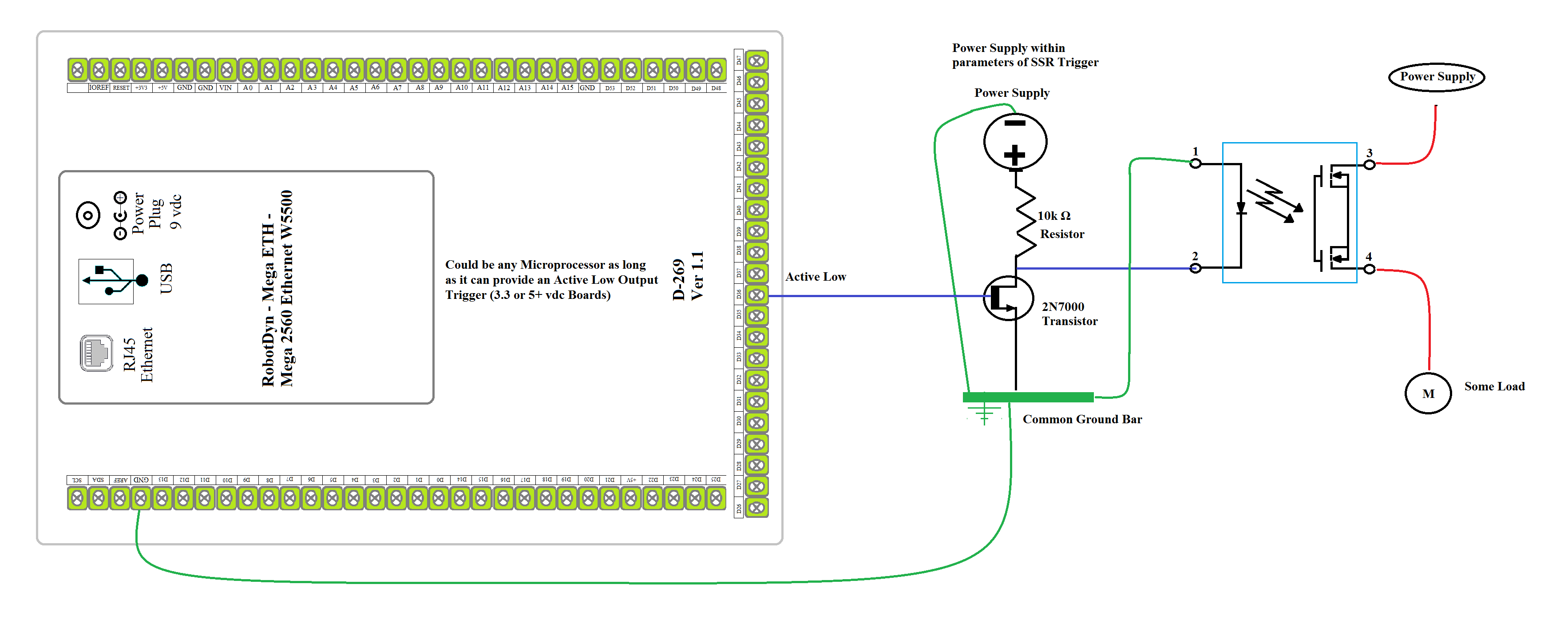
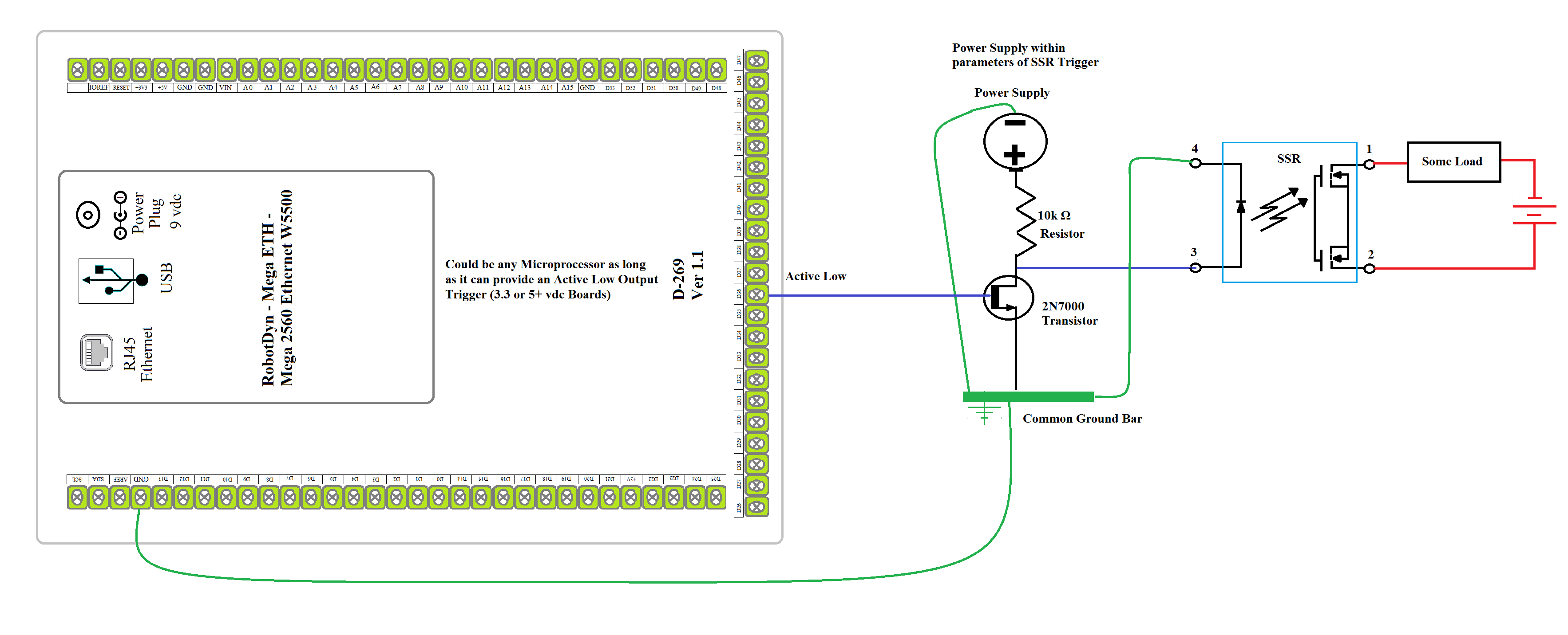
I have created my own schematic
active low.png
based on yours. Do I have it correct?
 
I can also add that on my particular GC board, PWM is also not working on pin #11 and #48. This is all with the Ethernet version of the 45 Grand Central firmware. I can also add that the ethernet communication issue I am seeing is odd. Take analog inputs A4 or A5 (pins 104 and 105). If I hook up a 3.3V analog input to it and then power cycle the GC, BruControl does its normal thing of connecting in a few seconds and then within 5-10 ms, it will state "Error...no device response". BC will not connect back to GC but if I pull the 3.3V analog input from either A4 or A5 and power up the GC, then BC does its normal connection over Ethernet right away, then it states that the device did not respond and is disconnected, then it will try to reconnect for 30-45 seconds and will reconnect. Oddly enough, if I then reconnect the 3.3V analog sensor back to pin A4 or A5, the pin works normally, takes the input as one would expect and all is well still with connectivity of Ethernet between the GC and BC software. Even more odd perhaps, other analog inputs with the same 3.3V sensor input do not show this same behavior. They take the analog input as expected and do not prevent BC from communicating to the GC controller over Ethernet.

Perhaps this is related to my particular GC controller or install in some fashion but I currently cannot use A2, A4, or A5, 43 as a DI or it prevents a permanent connection between GC and the BC software of Ethernet. Also as mentioned previously, pins #8, #9, #11, #45, and #48 do not output a PWM signal. I haven't messed around with serial connections yet.
 
Last edited:
OK, one last question for (for the moment). I see a number of things to potentially address this concern but I suspect there are some ways that are better than others. The problem I am having is that I have a 3.3v PWM signal coming from the Grand Central controller going to the BruControl AA-1 board as I need a true analog output for speed control of some pumps, etc. Perhaps as expected (I am not sure), I can no longer get the AA-1 board to deliver a 0-5V signal output from the 3.3V PWM input signal. I get 3V max output with 5V connected to the AA-1 VCC, and a 4V max if 12V is connected to the AA-1 VCC (24V makes no difference). Is there a good way to rectify this problem?
 
Sorry for all the posts but I'm not sure what is going on with the Grand Central as it is acting more and more alpha the more I try to make it work. The GC will occasionally not "boot" correctly as far as I can tell and the Neopixel turns red and power cycling doesn't resolve it. I have been able to rectify this only by reinstalling the firmware but now the old "termite none response" problem is back when setting up the ethernet shield with this board.

Side by side I have the GC, a Sunfounder MEGA 2560 Rev 3, a W5500 ethernet shield, and a Windows 10 computer. Install the V45 firmware for the MEGA 2560, then select option #2 from the firmware installer and termite brings up the expected network setup with the %0&15 command. Hook everything up and the MEGA and ethernet shield works, BC connects and everyone is happy.

Now do it with the GC and the blank stare of termite not providing anything back from the GC shows itself. Installing the firmware on the GC is a bit different in that you need to double press the reset button to get into the bootloader state. You do that and the board reboots and comes back with a different Com port. Use the new com port to install the firmware and the board reboots automatically. This takes it out of the bootloader state and back to normal once again. The com port goes back to the previous number. From here it is not clear what to do but I have tried both ways without success (trying to configure the networks settings both in and not in bootloader state). I was able to configure it one time however, so it did work once and I believe it was in the boot loader state but just not anymore. The variability of it all is the worst part.

So I took the GC and loaded up the simple blink program that Adafruit has for it and sure enough it uploaded and works as expected. I am unclear as to what the problem may be but I would say that the Grand Central is not quite ready to be used in BC (at least in my brewery), so plan accordingly if you look to convert over from another board at this point in time. It would be good to hear from some others and what issues or successes you have had with the GC.
 
@VacationLand... I just realized a problem with SAMD micros that will prevent them from passing through an initialization on the I2C bus, effectively stalling or delaying the FW from entering into normal operation. That init looks for an LCD display on pins 20/21, and with nothing attached there gets hung. So, please use 2.2k or similar resistors to pull those pins up to 3.3V.

This problem happens with the Feather as well and is a well documented problem. The pull-ups should resolve the stalled boot problem, but as far as the oddities above with those pins, I’m not sure what the solutions are until I test it myself. I do appreciate you forging the path though!!
 
Too much in a hurry. Cleaned it up. I do not know much about circuits so mostly copy and paste.View attachment 629107

This still isn’t correct, and neither is the hand sketch. The FET (Field Effect Transistor) provides a path to ground, so the + SSR terminal should be tied to positive voltage and the other between the resistor and the FET. When the FET is on, the circuit is completed.
 
Back
Top