BruControl: Brewery control & automation software

Homebrew Talk - Beer, Wine, Mead, & Cider Brewing Discussion Forum

Help Support Homebrew Talk - Beer, Wine, Mead, & Cider Brewing Discussion Forum:

This site may earn a commission from merchant affiliate links, including eBay, Amazon, and others.
Hi all,

FYI we added pressure sensors for those inquiring about measuring liquid volume in their kettles. See https://brucontrol.com/buy/sensors/

Very Nice! Do they have a quick disconnect so the kettle can be moved without yanking the cord out, or do you have to remove the tri-clamp?

Any plans to offer an NPT version? Hooking up a tri-clamp fitting on the side of an Igloo cooler/Mash Tun isn't that easy...
 
Products like these pressure sensitive switches are far beyond the scope of my current, albeit set back, attempt to convert from a totally hands on propane set up to electric brewing but they make me curious none the less. I'm assuming these are used in conjunction with automated valves for safely filling kettles? Is it possible for them to serve multiple functions such as making sure an element couldn't be turned on before there was enough liquid in the kettle as well as limit the amount in the kettle to avoid overflow? Or would this require one of these for each function you wish to control?
My panel is months away from being done and automation is just a pipe dream at this point but I'm trying to do things in such a way that upgrades and expansion are possible so I like to know how things work and can maybe do a little future proofing while I'm putting things together.

Sensor (not switch as those are binary ON/OFF) data can be used in multiple ways. Once the data is in the automation controller, you can do essentially whatever you want with it (you only need one per vessel you want to measure). First, the system can report the vessel levels on screen - like a digital sight glass or volume markings. But also that data can be used for automation sequences. For example, in the Mash tun: automatically fill to a certain level, monitor impending stuck mashes and automatically adjust recirculating rate, and perform electronic auto sparging. In the boil kettle: fill to a certain volume, calculate boil-off rate, and automatically transfer to the fermenter.
 
Sensor (not switch as those are binary ON/OFF) data can be used in multiple ways. Once the data is in the automation controller, you can do essentially whatever you want with it (you only need one per vessel you want to measure). First, the system can report the vessel levels on screen - like a digital sight glass or volume markings. But also that data can be used for automation sequences. For example, in the Mash tun: automatically fill to a certain level, monitor impending stuck mashes and automatically adjust recirculating rate, and perform electronic auto sparging. In the boil kettle: fill to a certain volume, calculate boil-off rate, and automatically transfer to the fermenter.

Thank you. I realize it's probably a pain trying to explain things to someone like me that is basically clueless about anything beyond basic electrical work but I honestly appreciate it. Hopefully in the future I'll be able to put to use the things I learn here from you and others.
 
The DIN connector can be removed. That said, you really should move on to CIP!

Yes, we can do a 1/2" NPT version.

Nice to hear you can do the 1/2" NPT. Bobby sells a couple of bulkhead options for a cooler, so adding a sensor to a mash tun cooler would work fairly easy.

I agree on CIP but that's a long way off. Still have the Brew Room construction and conversion to BruControl to accomplish before I can start the next upgrade!

My biggest problem with CIP is how to seal the kettle lid. Any thoughts?
 
I’ll throw this out there for consideration with all the noise issues: SSRs generally engage when the AC voltage crosses zero, whereas mechanical relays engage regardless of where the AC sine wave is. If switching over to SSRs is fixing the issue, this might be part of it?
 
I’ll throw this out there for consideration with all the noise issues: SSRs generally engage when the AC voltage crosses zero, whereas mechanical relays engage regardless of where the AC sine wave is. If switching over to SSRs is fixing the issue, this might be part of it?

Assuming it is a zero-crossing SSR, then yes. But most [cheap-o's] aren't.
 
Got around to adding one of the analog amplifier boards to drive the proportional valves today. Previously used an R-C filter straight out of the MEGA, so this didn’t solve a problem but should reduce some current load off the MEGA. I will also use it to drive my proportional SSR, but that’s a job for another day!
IMG_4405.jpg
 
Well. I ended up having a disconnect yesterday some time. And of course it froze with the compressor on and the conicals valve open. So I got home to my beer at 35f instead of 68. Sigh.
 
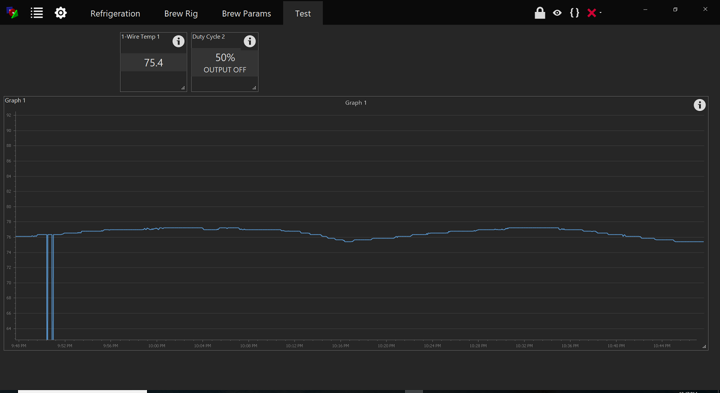
Built a test bet today to try to solicit some resets/temp spikes/aberrant behavior. Creating as sloppy a circuit as possible, using a MEGA w/Wi-Fi shield, a 12 VDC active-low relay, and a 1-wire sensor, I was able to induce some spikes on a 1-wire probe. Here are two that occurred in in close time sequence. I will be testing this further to see how to squash it effectively. Stay tuned!

spikey.png
 
I've been following this thread for a while and have almost completed my build. I'm not a hardware guy at all, I'm a software guy, but thanks to this thread I'm almost to the finish line. Can't say thanks enough, the thread has been a great resource for a newcomer like myself!

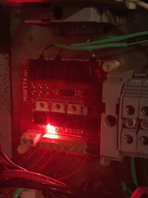
I'm testing things out and I'm having an issue with my pumps that I hope someone could help me out with. I'm using the 24v tan DC pumps with a 4-channel MOSFET board to control them. Similar I think to what @augiedoggy has setup.

I can turn the pumps on and off through BruControl and LED's on the board turn on and off as expected but the problem I'm having is that all the channels on the board are reading 24v no matter what input is. So when the panel powers up, and the pumps are plugged in, they are always running.

 
Last edited by a moderator:
I have the signal pin on each of the control inputs wired up to a digital output pin on the Mega 2560.

The 24v DC power supply is connected to the power input and each pump +/- is connected to channel output +/-. It seems relatively straight forward but I'm obviously missing something.

IMG_1398_2.jpg
 
Are the two power supply's grounds tied together? Also is there i ground line coming into those connectors? If you only have 1 input signal to the board, it will be 5V but it needs to be referenced to something - without a ground that's not possible.
 
Yes, the 5V and 24V grounds are tied together. The control inputs pins are Ground, Vcc and Signal from left to right. I didn't have the ground wire connected because I read the input and output grounds are tied together. I just added a ground wire to all the inputs. Still getting the same issue.

I just read a comment on the Amazon product page that power input and all four outputs are tied together. That doesn't make sense to me.

Here's the quote..
"This board contains four low-side IRF540 mosfet switches. The +
terminal of the power input and all four outputs is connected
together, which make these ideal for driving "analog" RGB LED strips."
 
The control-side Vcc pins are tied together but not used. I'm curious if the metal dc power jacks for my pumps that are mounted to the panel are grounded and causing the issue.

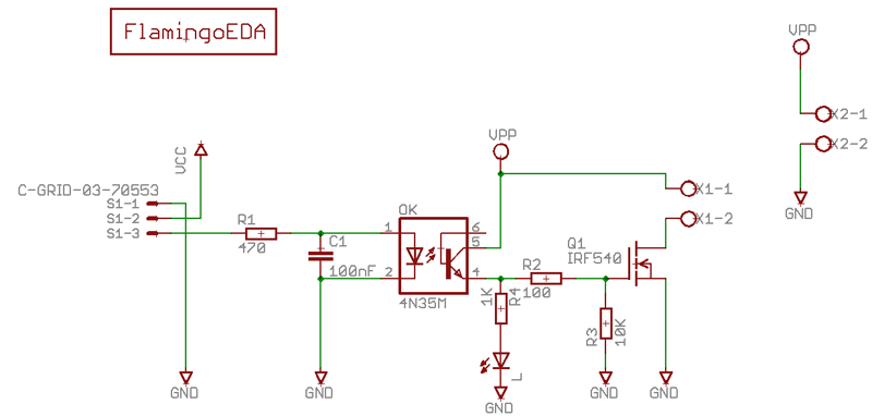
This is the schematic for the MOSFET board.

PowerFET-4Channel-800.png
 
Yep the metal dc power jacks attached to the panel are causing the issue. I temporarily removed them from the panel so it wouldn't be grounded and it works as it should.
 
First, you are correct that the grounds are tied internally. Looks OK to me... 5V input on S1-3 should trip the opto. One way to find out is to put a meter on pin 4 of the opto - but then again you did say the LED is lighting on/off properly, so that measurement is actually moot (nice they put the LED on the output of the opto instead of the input!). That is directly wire to the gate, so I am kinda at a loss to say where the problem is occurring. Might want to check the FET with a just a meter and no load.
 
Built a test bet today to try to solicit some resets/temp spikes/aberrant behavior. Creating as sloppy a circuit as possible, using a MEGA w/Wi-Fi shield, a 12 VDC active-low relay, and a 1-wire sensor, I was able to induce some spikes on a 1-wire probe. Here are two that occurred in in close time sequence. I will be testing this further to see how to squash it effectively. Stay tuned!

View attachment 579472
I currently get these on some of my rtd graphs when even the central air kicks on in the building. Why is this not an issue with pids and such? If its just a matter of sloppy circuit which I assumes poorly oriented /component layout and wiring? I really would like to get this resolved. I layed out my panel so all the low voltage stuff was at the top and the rtd wiring is as isolated as possible from the rest of the panel but it seems that isnt stopping the voltage interruptions from coils and relays from causing these issues.

I have a large noise filter I can wire to the ac which supplies all my dc power but I seem to still get spikes even when the arduino is power via only usb from the pc.

Ive been thinking and wonder is the fact that my float switches for the rims and HLT switching the ground could be creating a ground loop of sorts? I could swap the circuit to the hot side if you think it would help with this? I may temporarily remove and jumper the wiring to test its effect.
 
That's crazy. Something is definitely not right there.

I would never power the interface from the PC's USB. It should always have a solid power-supply. The PC is too noisy and definitely not enough power to supply it for anything other than testing work. When you power it externally and connect the PC, it takes the external power anyway.

You may have a ground loop - all grounds should be tied to one point. Again, without a schematic, it is very hard to diagnose remotely.
 
Ok so I discovered some noise is definitely ground related... my rtd probe wires from my control panel to kettles have a grounded shield wire which was grounded at both ends to the xlr connector housing and therefore between the kettle and control panel.. once I disconnect the ground connection between the rtd connector and panel the spikes have stopped. I also had to disconnect the ground between my 12v powersupply output and main DC ground terminals. somehow it appears I had 2 ground loops, one between the RTD wire from panel to kettle and the other when I tied all the DC grounds together. When I try to run a wire from the arduino shield Ground output to the main DC ground terminal I got the most spikes (again creating another loop).. once I isolated everything powered off the arduino to not share the grounds with the 24v pr 12v DC grounds everything started working correctly.
 
Last edited:
On a side note now that everything seems to be working correctly. .. while not at all the same as testing with grain, my double 2200w cartridge heater rims (4400w total) is steadily raising 75 gallons of water 1 degree every 2 minutes or so.. I imagine when the grain is in the mashtun to prevent the return wort from mixing instantly with the entire mass at once the results may be more favorable since I'm actually recirculating at about 5-6gpm at the moment.
 

Attachments

  • 20180716_131020.jpg
    20180716_131020.jpg
    3.3 MB · Views: 74
5-6 gpm? How big is the mlt? Mine is a 20g G1 and if I recirculate much faster than 2gpm bad things happen...

Cheers!
Theres no grain, im just running water tests... I dont plan on recirculating more the 3-5gpm.. this is a 3bbl system (Stout/sungood kettles) with a much larger false bottom.
 
Last edited:
One aspect of my personal brewery that I have found really useful is the use of the pressure sensor in the MLT. It is normally used to measure MLT volume, but I also use it to detect if the mash is sticking. During mashing, if the pressure drops past a certain threshold, the proportional valve feeding the recirculation is closed by 1%, otherwise it opens by 1% (within limits). This check repeats twice a minute. At the beginning of the mash, the valve tends to run at the bottom of the range (maybe 4-6 qpm), then by the end, it is fully open and ripping at ~18-20 qpm.

It’s pretty cool to inspect the science of the mash as it evolves: going from cloudy to clear, from sticky to loose, etc.
BrunDog,

This is exactly the sort of thing that makes me so excited about BruControl. Can you post your current brew script (or link to where they're posted) so that we can learn from it? I know you've posted some/all of your brew script in the past. If it's largely unchanged, I can just read that.

Thanks!
-Adam
 
Back
Top