BruControl: Brewery control & automation software

Homebrew Talk - Beer, Wine, Mead, & Cider Brewing Discussion Forum

Help Support Homebrew Talk - Beer, Wine, Mead, & Cider Brewing Discussion Forum:

This site may earn a commission from merchant affiliate links, including eBay, Amazon, and others.
so while I wait for parts to arrive I decided to do so research on arduinos and supposedly the I/O pins on a mega can handle up to 40ma unless im missing something?

40mA would be an absolute max which will be the failure point. They must be less than 20 and ideally 10 or less. Most relay boards and SSRs stay below this. But wiring multiple SSRs will exceed the requirements.

You could put each SSR on different pins and run device elements for each that reference the same sensor if you wanted. They will work the same but give you individual control. Or use one large SSR to switch the total load rather than multiple small SSRs.
 
That’s the way it is supposed to work but even one aberrant reading is too many. Did we discuss reducing the length of your sensor wires if possible?

Since the one spike was on the glycol chiller, what I'm going to do is put a filter across the chiller contactor itself, if I see any more spikes.
 
40mA would be an absolute max which will be the failure point. They must be less than 20 and ideally 10 or less. Most relay boards and SSRs stay below this. But wiring multiple SSRs will exceed the requirements.

You could put each SSR on different pins and run device elements for each that reference the same sensor if you wanted. They will work the same but give you individual control. Or use one large SSR to switch the total load rather than multiple small SSRs.
I already purchased larger DC ssrs to drive the groups of ssrs. im just hoping that is in fact what caused my problems as everthing worked great for about 20 minutes..

:off: Rant..I have plenty of time it seems to sort all this out now because Our brewery opening has been delayed Due to the local inspector changing his mind about letting us use an ac unit with a coolbot (after we spent most of our budget and built the coolbot cooler) Now we have to hire a licensed engineer to put it in writing that the coolbot/ac unit is safe to use indoors.. Nevermind just about every other smaller brewery in surrounding cities and counties uses them.. Frustrating for sure.
 
Last edited:
I already purchased larger DC ssrs to drive the groups of ssrs. im just hoping that is in fact what caused my problems as everthing worked great for about 20 minutes..

:off: Rant..I have plenty of time it seems to sort all this out now because Our brewery opening has been delayed Due to the local inspector changing his mind about letting us use an ac unit with a coolbot (after we spent most of our budget and built the coolbot cooler) Now we have to hire a licensed engineer to put it in writing that the coolbot/ac unit is safe to use indoors.. Nevermind just about every other smaller brewery in surrounding cities and counties uses them.. Frustrating for sure.

You can use a transistor like a BC337 and a 1k resistor instead of an SSR to drive the other SSR's, and hide it in the heatshrink...

Also, you can call them back up and tell them you have decided to not run the coolbot because you understand their concerns... never admit to plans to putting it in, always affirm that you will have a licensed electrician do any changes... You will get a pass on the inspection and just put it in later... They do not understand how simple a cool-bot is... make their job easy.... they really don't care what you do later, they just want the ability to say 'it was to code when I inspected it' It took me two years to open, luckily my Friend and GC had built dozens of breweries and hundreds and hundreds of pizza chain joints and had a uncanny ability to predict what the inspectors and plan reviewers would see and say... At his request, I had UL approvals for camco elements, wire, L6-30 plugs, etc supplied to them and and just had them plug in to outlets the electrician installed... inspections passed, got our occupancy (after fighting over spinklers and winning with a $5,000 engineering bill), Then the BCS based controller went in.... and was changed... and changed... and changed to CBPi... and now changing to BruControl... I have pictures of mayor and building folks standing in front of the equipment to boot :)
 
^ my guess would be when the chiller kicks on or pump starts up. Thats when I still get them on my home system but only on one wire and rtd temp probes and not all of them. The 2 wire thermisters are rock solid for me.. I'm guessing from the 22 uf smoothing filter caps you use on the boards? I tried such caps on my one wire sensors and they helped a great deal but did not completely stop the spikes.
 
when the chiller kicks on or pump starts up. Thats when I still get them on my home system but only on one wire and rtd temp probes and not all of them.

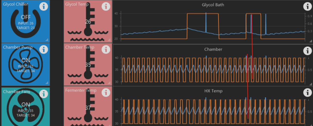
Here's a screencap from earlier today. I added the two red lines, since the 3-hour X-axis started getting crowded. I didn't see any when the X-axis was one hour. Prior to seeing this, I had only seen one spike, and it was on the glycol bath sensor. These are all 1-wire, btw.
Screenshot 2018-07-09 10.38.42.png
 
I looked at every page of this thread for the word 'workspace' before posting... Can a device be present on two workspaces with a different name? even if only one is enabled at a time?

I read that names are required to be unique, and I was trying to set up a workspace for two different functions, say a work space for 'brewing' and a workspace for 'cleaning', but both use the same pump and heating element. I want the workspace to show the main function that is being performed, different background, etc... and most items will be different... However, when I select add device, I can select the proper i/o, but then 'digital output' is no longer available (interesting, the other output types, duty cycle and hysteresis, are available) ...

I even wrote my first script to look at a switch on the workspace and if it was on, it enabled all elements, if it was off, it disabled them... this was done after i learned the hard way that creating a new configuration *disables* all devices on your old configuration when you switch back to it... safety, I am certain, but it was a doh! moment when you have 30 devices and they all go to 'disabled'..

Maybe I am thinking about how to do this wrong, maybe instead of having 'brewing' and 'cleaning' as workspaces, I should have them as scripts started by a button/switch?
 
so I installed the new rtd boards and the ssrs to control the other ssrs and replaced a smaller 2 relay board which was controling my 2 ac pumps because it seemed it was causing excessive spikes somehow, (I disconnected it and the spikes went away when turning the contactors on and off.) ... after replacing it the spikes went away for a short time when actuating the contactors but then they came back? The smaller high level relay board is being powered by a separate 5v supply but the ground is tied to the ground on the arduino. At this point im ready to rip the contactors out and just rely on the ssrs. Every time I think I have it figured out the issue returns it seems. had to put a coat of poly on the refinished floors but I hope to take another crack at it tomorrow.
 
Last edited:
I looked at every page of this thread for the word 'workspace' before posting... Can a device be present on two workspaces with a different name? even if only one is enabled at a time?

I read that names are required to be unique, and I was trying to set up a workspace for two different functions, say a work space for 'brewing' and a workspace for 'cleaning', but both use the same pump and heating element. I want the workspace to show the main function that is being performed, different background, etc... and most items will be different... However, when I select add device, I can select the proper i/o, but then 'digital output' is no longer available (interesting, the other output types, duty cycle and hysteresis, are available) ...

I even wrote my first script to look at a switch on the workspace and if it was on, it enabled all elements, if it was off, it disabled them... this was done after i learned the hard way that creating a new configuration *disables* all devices on your old configuration when you switch back to it... safety, I am certain, but it was a doh! moment when you have 30 devices and they all go to 'disabled'..

Maybe I am thinking about how to do this wrong, maybe instead of having 'brewing' and 'cleaning' as workspaces, I should have them as scripts started by a button/switch?

Devices were created, by design, to be unique. This is to avoid confusion and to ensure a script knows which device to affect. I can see the argument that you want the same device on multiple Workspaces, but unfortunately we didn't build it that way. As you noted, you can have different device types address the same I/O, but enabling one will automatically disable the others. This was also don on purpose, because of course you can't have the SSR which powers your boil kettle work in both Duty Cycle and PID modes simultaneously (but you can alternate by enabling the one you want to use). I'd have to think about the real need to accommodate this - I suppose we could create a mirror device, but in all truth that wouldn't be a high priority right now. Any more thoughts you have on this would be helpful.

Yes, configurations automatically disable all devices for safety. We didn't intend for configurations to be used commonly for different functions like brewing or cleaning, but I suppose you could. We will be ensuring more items carry across configuration changes in v1.1, like timer states and values.

On my personal rig, I have Workspaces for brewing and fermentation/dispensing. My brewing and cleaning scripts run independently but I watch the same Workspace through each process, as I am accustomed to what each device element means and its location on screen.
 
so I installed the new rtd boards and the ssrs to control the other ssrs and replaced a smaller 2 relay board which was controling my 2 ac pumps because it seemed it was causing excessive spikes somehow, (I disconnected it and the spikes went away when turning the contactors on and off.) ... after replacing it the spikes went away for a short time when actuating the contactors but then they came back? The smaller high level relay board is being powered by a separate 5v supply but the ground is tied to the ground on the arduino. At this point im ready to rip the contactors out and just rely on the ssrs. Every time I think I have it figured out the issue returns it seems. had to put a coat of poly on the refinished floors but I hope to take another crack at it tomorrow.

There is another user here who is having spike problems too. This has become a very high priority and I am working to figure out where it is coming from and how to mitigate it. Curious: have you installed the snubbers?
 
There is another user here who is having spike problems too. This has become a very high priority and I am working to figure out where it is coming from and how to mitigate it. Curious: have you installed the snubbers?
I have installed the snubbers across both the coils and I also installed these https://www.ebay.com/itm/50-1uF-250...e=STRK:MEBIDX:IT&_trksid=p2057872.m2749.l2649 across the power inputs and load on the contactors.. I have installed ferrites as well.

When I put the snubbers across the arduino relay board they seemed to work but then the relay board started acting weird that day although I am not sure the 2 were related because I also had the loose ground issue I found after swapping it out. (I was experimenting with isolating power and ground wires at the time)
 
Devices were created, by design, to be unique. This is to avoid confusion and to ensure a script knows which device to affect. I can see the argument that you want the same device on multiple Workspaces, but unfortunately we didn't build it that way. As you noted, you can have different device types address the same I/O, but enabling one will automatically disable the others. This was also don on purpose, because of course you can't have the SSR which powers your boil kettle work in both Duty Cycle and PID modes simultaneously (but you can alternate by enabling the one you want to use). I'd have to think about the real need to accommodate this - I suppose we could create a mirror device, but in all truth that wouldn't be a high priority right now. Any more thoughts you have on this would be helpful.

Yes, configurations automatically disable all devices for safety. We didn't intend for configurations to be used commonly for different functions like brewing or cleaning, but I suppose you could. We will be ensuring more items carry across configuration changes in v1.1, like timer states and values.

On my personal rig, I have Workspaces for brewing and fermentation/dispensing. My brewing and cleaning scripts run independently but I watch the same Workspace through each process, as I am accustomed to what each device element means and its location on screen.

Thank you for the very informative response... I think I will look into doing the desired functions with scripts operated by a physical button and/or gui button, and having the script just disabling unused items(or enabling the used items and disabling all on exit)
 
Chiller

Temp sensor (Glycol Reserve Temp) one wire sensor in the gylcol reserve tank

Valve (Recirc Loop)- 12v 2 way valve- when open this runs gylcol though the loop past theother FV valves. This keeps the loop cool, and helps with evening of gylcol reserve tank temps. (port 11)

Pump (Glycol Pump)-120v pump, it is the only pump- so it needs to be running in conjuction with any flow/cooling. (port 10)

Hysterisis (Glycol Temp Setting)-using compressor as the actor and temp sensor (Gylcol Reserve Temp) to maintain 25F in the glycol reserve tank. (port 12)

This loop is... pump out from reserve tank------>though valve(Recirc Loop)--->reserve tank in. When the fermenters are in service this loop will run 24/7 This keeps the glycol at 25F using Hysterisis (Glycol Temp Setting), ready to chill the FV's when they call.
FV1 and FV2 valves closed.


FV1

FV1 Temp sensor (FV1 Beer Temp)-one wire sensor in thermowell

FV1 Hysterisis (FV1 Set Point)-using valve 12v 2 way valve ( Port 6)

When FV1 calls for cooling, it will open its valve, close recirc Loop valve. While everything else stays the same ( Pump on, glycol maintaining temp).

When FV1 is at setpoint (using FV1 Hysterisis) it's valve closes, and recirc Loop opens. I guess it can be looked at as a 4 way valve, just diverting the constant flow somewhere at all times.


FV2

FV2 is going to be the exact same as FV1

FV2 Temp sensor (FV2 Beer Temp)-one wire sensor in thermowell

FV2 Hysterisis (FV2 Set Point)-using valve 12v 2 way valve ( Port 9)

(denote actual names)


Now FV1 and FV2 will call at the same times sometimes, which should be no big deal.

Sorry to bring this back up from the depths... Would like to use it today and struggling with it.

Thanks
 
Sorry to bring this back up from the depths... Would like to use it today and struggling with it.

Thanks
What are you having an issue with specifically? If it helps I dont bother with the recirc loop valve myself and have had no issues with the 4 conicals I control.The glycol in my manifold drains back to the chiller sump when its off so no need. I do use a single 240v pump in my chiller which is triggered by one of the poles on a DPST relay. The other pole on that relay activates the valve that needs to open when the pump kicks on. (I have four of these relays, one for each fermenter) I have a bypass valve which is slightly cracked open to allow some pressure relief but may change that to a pressure relief valve since it makes more sense. I also have heating strips on their own relays
 
Before I put fingers to keyboard, I am wondering why this can’t be controlled fully with Hysteresis devices? All can reference temperatures to open/close valves or turn pumps on/off. Please verify.
I am using hysteresis to do just that. Do you mean by using scripts or additional devices to turn on or off multiple inputs at specific temps referenced by the same probe? That would work too rather than tying the hardware to a single relay.
 
Well I like to be able to just set temp in one spot ( per fermenter), and have scripts do the rest.

i.e. FV1 temp is going to be 45F. When I select 45F, that would then turn on the compressor to make sure its Hysterisis loop is set to 20F( and maintained) the Glycol pump is turned on, and if the fermenter needs cooling the FV1 valve is opened. If FV1 cooling is not needed then close FV1 valve. If all are at thier setpoints the glycol pump would turn off until its needed again.

Then FV2 would be the same.

I COULD just run the glycol pump 24/7, but it seems unnecessary if its not needed.. I am not sure how to control this with Hysterisis. I mean, right now the FV's use HY, to open their respective valves, and the compressor runs on its own HY with a probe in the glycol reserve. The pump is the wild card for me.

I could put the pump always on and run the recirc loop valve on a HY, no problem. But seems like a waste to me...


Short story long, I have 3 valves and 1 pump. That one pump needs to share time with those valves. So I am not sure how to accomplish that.
 
Maybe with an if/then line in your script?

IF FV1=0 and FV2=0 and FV3=0, then pump=0
IF FV1=1 or FV2=1 or FV3=1, then pump=1

Not sure about the exact syntax, but you get the idea.
 
So I was playing with the setup tonight trying to get it to stop freezing/disconnecting when relays are shut down. I moved the feather completely out of the control panel. I then shut the control panel. So all the relays and power were in the control panel and the feather completely out of the panel. It still had the same issues of randomly freezing/disconnecting. I don’t think it’s in interference thing. Maybe a overvolt or something backfeeding from the relay over the control wire because as I said the feather and the relays are not even in the same Vacinity. The feather locks up completely and stops transmitting everything.
 
Well I like to be able to just set temp in one spot ( per fermenter), and have scripts do the rest.

i.e. FV1 temp is going to be 45F. When I select 45F, that would then turn on the compressor to make sure its Hysterisis loop is set to 20F( and maintained) the Glycol pump is turned on, and if the fermenter needs cooling the FV1 valve is opened. If FV1 cooling is not needed then close FV1 valve. If all are at thier setpoints the glycol pump would turn off until its needed again.

Then FV2 would be the same.

I COULD just run the glycol pump 24/7, but it seems unnecessary if its not needed.. I am not sure how to control this with Hysterisis. I mean, right now the FV's use HY, to open their respective valves, and the compressor runs on its own HY with a probe in the glycol reserve. The pump is the wild card for me.

I could put the pump always on and run the recirc loop valve on a HY, no problem. But seems like a waste to me...


Short story long, I have 3 valves and 1 pump. That one pump needs to share time with those valves. So I am not sure how to accomplish that.
I do exactly what you are saying here... pump only comes on when the flow is needed and the valve for whichever of the 4 needs to open. its super east to do with a relay with 2 sets of no contacts. the relay closes both at the same time. one set turns on pump and other opens the valve, thats it, super simple
 
Is the power source to this feather sharing an AC feed that has a big honking load being switched on and off?

Cheers!

I thought about this as well so powered the feather off a separate power supply ( different power than then control panel, but same 120v circuit) after the last hiccup. Only time will tell.
 
So I was playing with the setup tonight trying to get it to stop freezing/disconnecting when relays are shut down. I moved the feather completely out of the control panel. I then shut the control panel. So all the relays and power were in the control panel and the feather completely out of the panel. It still had the same issues of randomly freezing/disconnecting. I don’t think it’s in interference thing. Maybe a overvolt or something backfeeding from the relay over the control wire because as I said the feather and the relays are not even in the same Vacinity. The feather locks up completely and stops transmitting everything.

Curious... what relays?
 
Whatever 8 relay non din rail is linked on your site. But they are the ones that need a 12v feed and a 5v feed (super dumb).
 
Whatever 8 relay non din rail is linked on your site. But they are the ones that need a 12v feed and a 5v feed (super dumb).
the 5v feed is the one normally coming from the arduino and ideally should be isolated completely from the 12v feed which powers the mechanical relays.. supposedly 12v relay coils are more reliable and 12v power supplies are more commonly used vs 5v.
 
So I was playing with the setup tonight trying to get it to stop freezing/disconnecting when relays are shut down. I moved the feather completely out of the control panel. I then shut the control panel. So all the relays and power were in the control panel and the feather completely out of the panel. It still had the same issues of randomly freezing/disconnecting. I don’t think it’s in interference thing. Maybe a overvolt or something backfeeding from the relay over the control wire because as I said the feather and the relays are not even in the same Vacinity. The feather locks up completely and stops transmitting everything.
Its definitely voltage spikes for me from the actual load though not the coils because if I turn off my breakers after my contactors it stops doing it when actuating those contactors. I actually measured them on my digital I/O pins when I turn the contactors on and off in my setup. my 12v power source was rock solid however.

I have tried a number of different relay boards some are way worse than others. (the two active low boards I tried were doing it almost every time) The snubbers worked best when I had them up on the relay contacts (which doesnt make much sense to me based on my above comment) but I removed them when my relay board went haywire. also since the issue happens when the arduino is powered via the usb orr another power circuit I am condident its coming through the relay board.. I have a 4 channel ssr board but that wont let me wire it to prevent multiple kettles from being on at once.. I thought about secondary switching the ssr control voltage with the NO/NC contacts but read these are a very poor choice for low voltage dc loads

The DC SSRs I bought are working good to power my other ssrs and all my replacements RTD amplifiers are working fine so this is the last issue to sort out for me.
 
Last edited:
For those interested, these are three sources of industrial Arduino compatible controllers. We haven't validated any, but I am very confident they would work:

https://industruino.com/ (D21G)
https://www.industrialshields.com/ (M-DUINO)
https://controllino.biz/ (MAXI or MEGA)

Does anyone see any operational issue with using BruControl and this model of the middle one for a small commercial panel that you wanted a more pro look and did not want bare circuit boards showing?

https://www.robotshop.com/en/m-duino-plc-arduino-ethernet-58-i-os-analogdigital-plus.html
 
Back
Top