BrewCommander - Impressive offering from John

Homebrew Talk - Beer, Wine, Mead, & Cider Brewing Discussion Forum

Help Support Homebrew Talk - Beer, Wine, Mead, & Cider Brewing Discussion Forum:

This site may earn a commission from merchant affiliate links, including eBay, Amazon, and others.
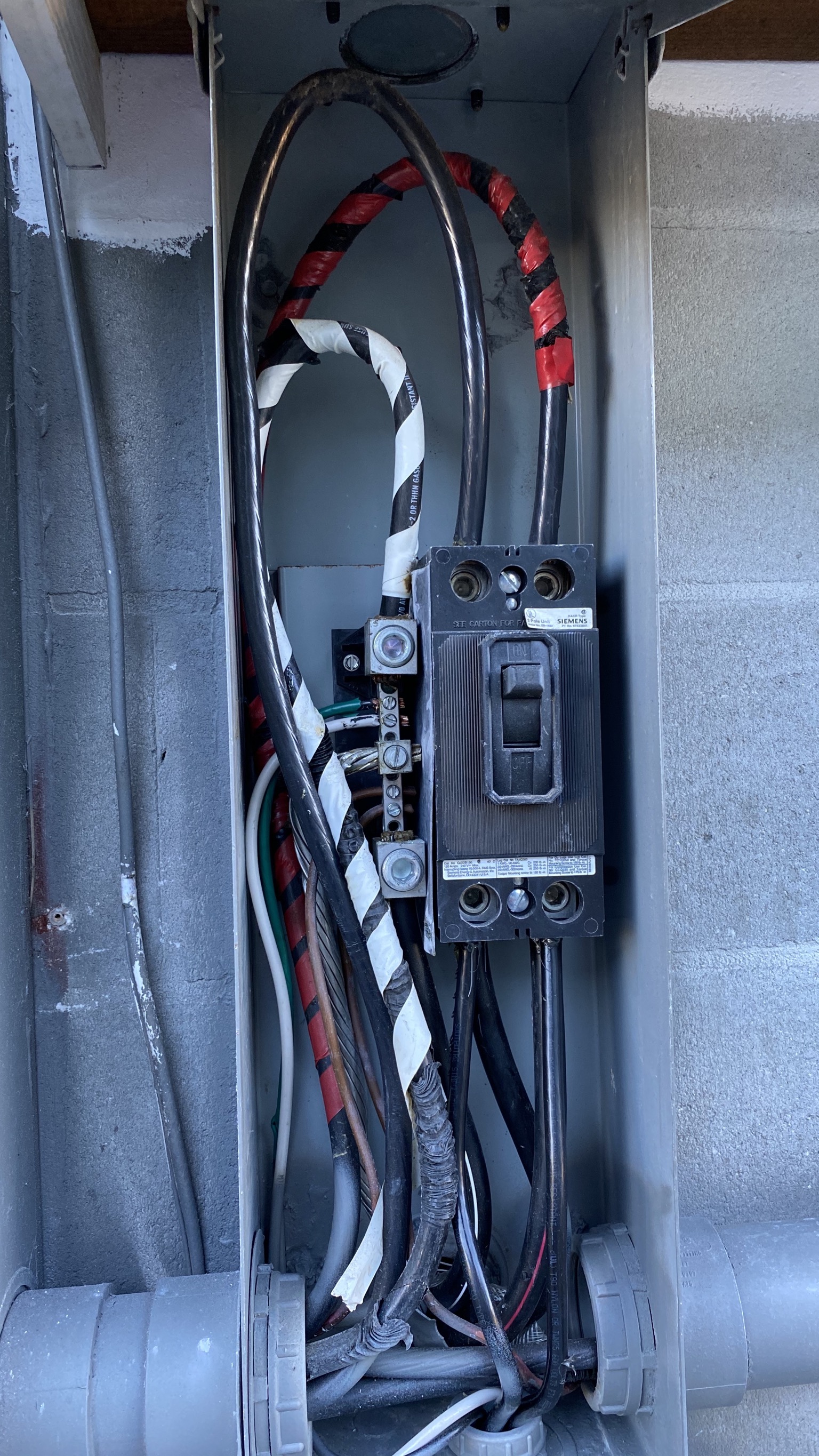
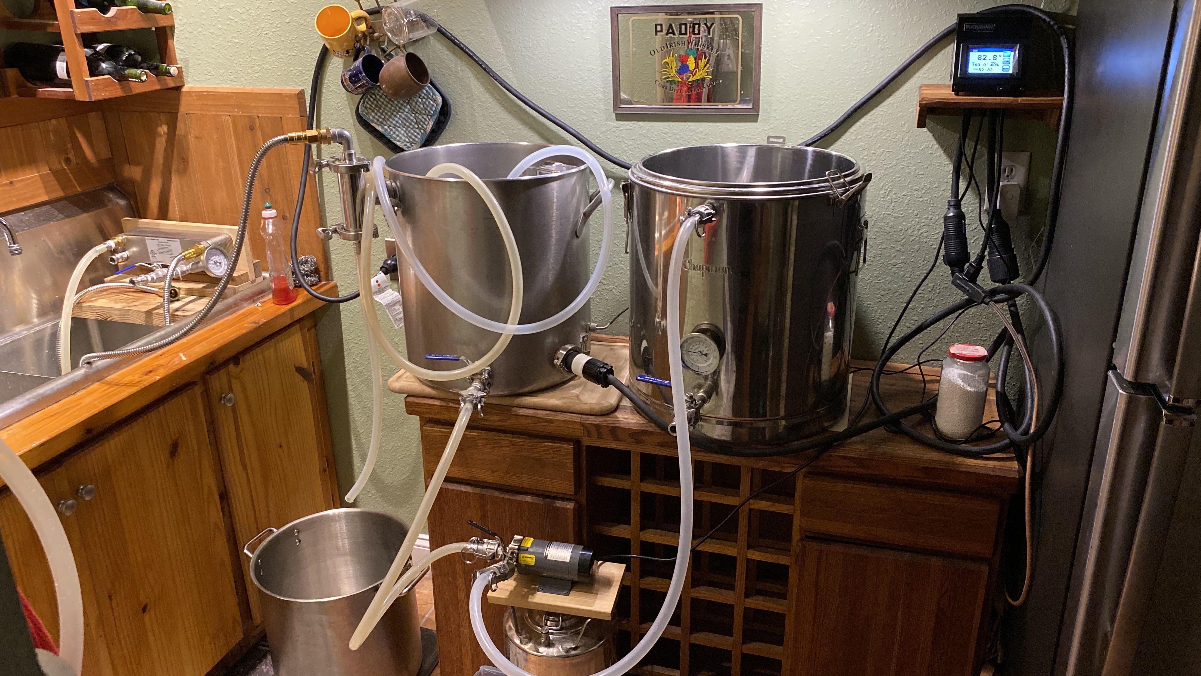
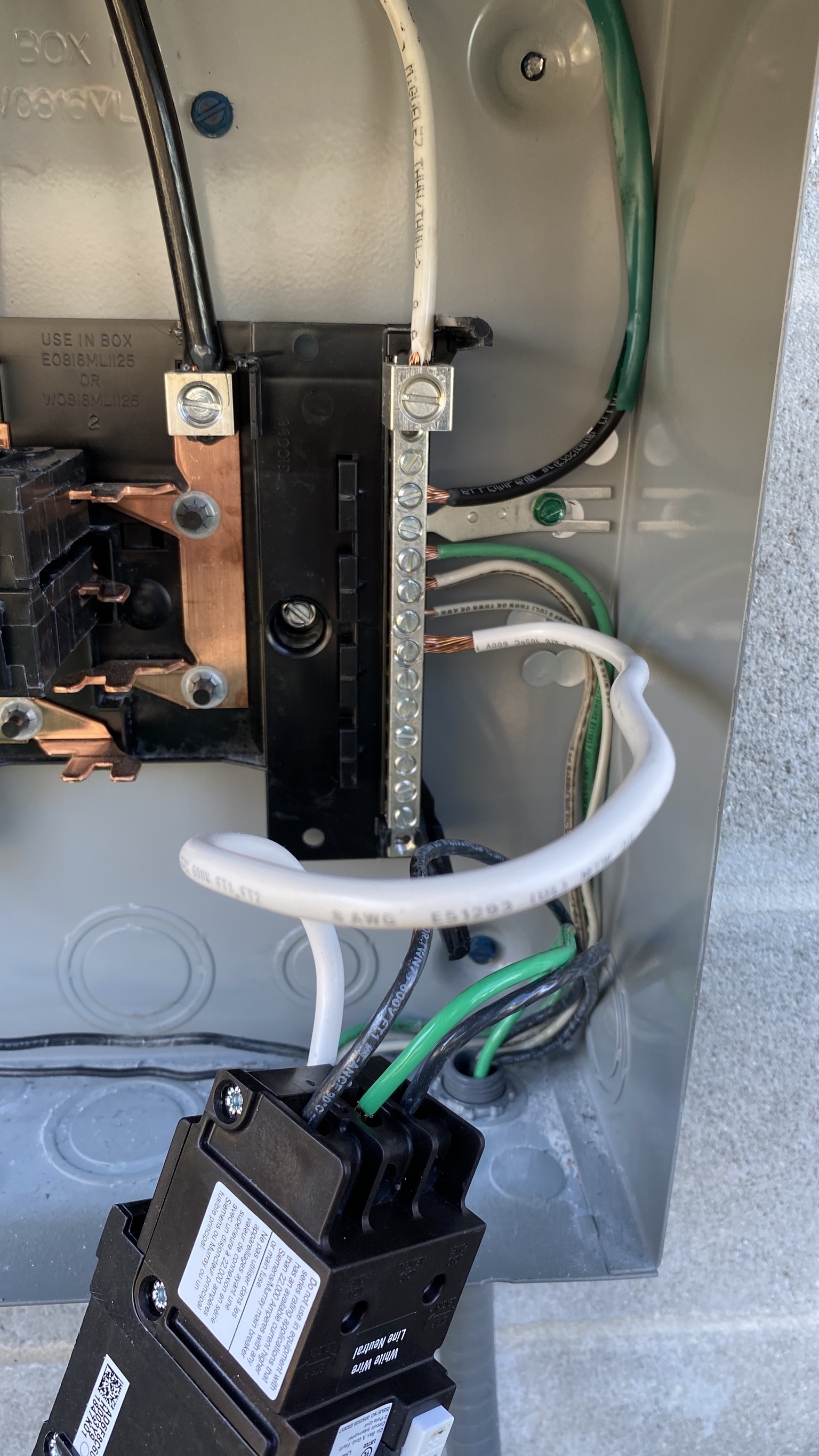
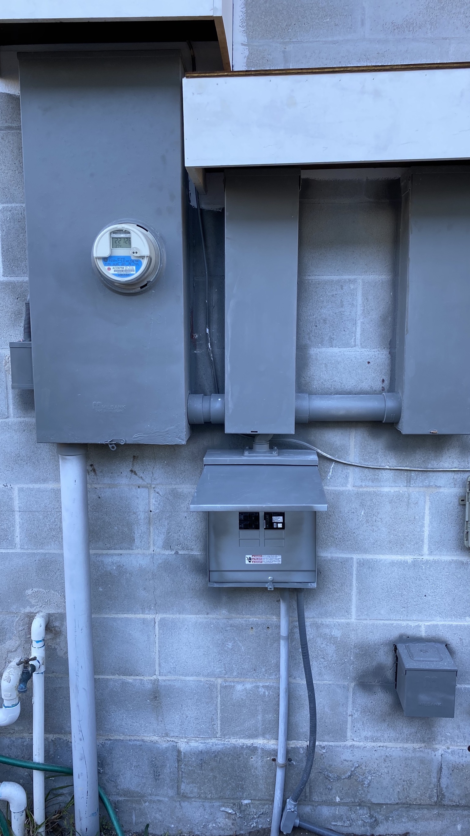
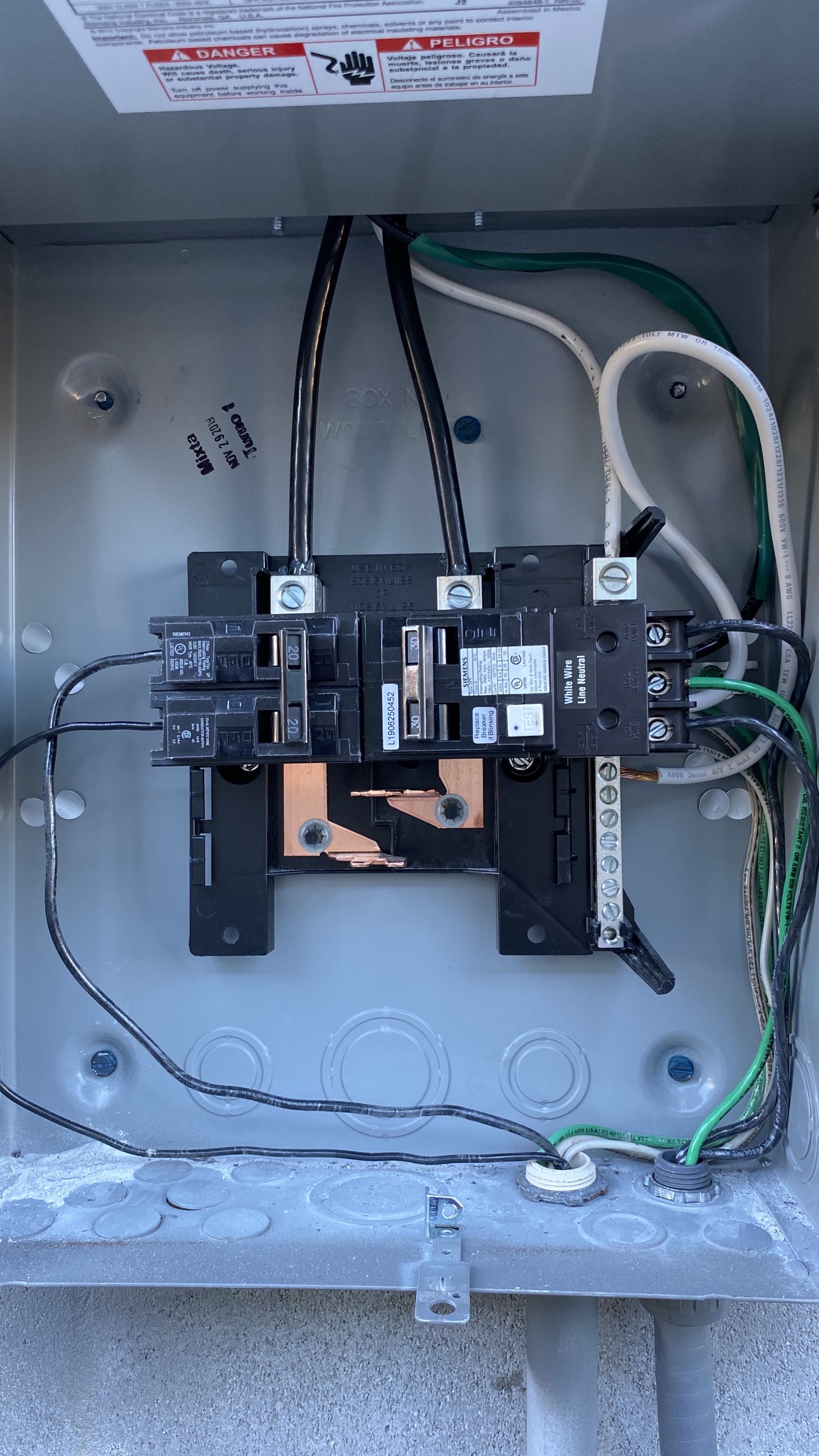
So last nights first Brew was a total disaster. I had tested the Brew commander and was having a problem where when the 120 V plug was plugged into the wall it would shut off the controller and trip the 30 amp circuit breaker. That is a new circuit with a 30 amp GFCI running into 100 amp sub panel. The 120 V is simply the closest wall receptacle. I sent that BC unit back thinking there was a problem with it, got another one and the exact same thing happened. I ran an extension cord to an outlet across the room and it worked.tested a full brew session with water. No issues using the other outlet. So in the middle of the actual brew last night I’m about to start recirculating the mash during and as soon as I get push pump button everything shuts off with the brew commander and it has tripped the 30 amp GFCI breaker.
I’m not sure what’s going on here, when powering the unit with just the 240 amp circuit everything works fine. When I plug in the 120 V to the wall receptacle it is tripping the 30 amp breaker but it is not tripping the breaker for the 120 V wall receptacle. I plug the pump directly into both of the wall receptacles that I tried and it works just fine. Any ideas what might be a problem? Thanks
 
Last edited:
Sounds like there is something wrong with the 30A GFCI breaker installation. There appears to be some kind of crosstalk between that circuit and what should be independent 120V circuits.

Brew on :mug:
 

Attachments

  • 35E46A22-E481-4319-874F-AA329CCF0457.jpeg
    35E46A22-E481-4319-874F-AA329CCF0457.jpeg
    960.6 KB · Views: 59
  • 129FF82B-9089-460C-AEC8-1665440E04F2.jpeg
    129FF82B-9089-460C-AEC8-1665440E04F2.jpeg
    871.7 KB · Views: 64
  • 327E75C3-B693-41D4-AE0B-B0B2785E829A.jpeg
    327E75C3-B693-41D4-AE0B-B0B2785E829A.jpeg
    930.5 KB · Views: 67
  • 06DFE465-B03E-4110-9290-49E04FC8D906.jpeg
    06DFE465-B03E-4110-9290-49E04FC8D906.jpeg
    2.6 MB · Views: 62
That 30A GFCI breaker is wired wrong! The green ground wire should connect to the ground bus in the sub panel. Since you don't have a neutral connection in the outlet for the BrewCommander 240V input, there should be no connection to the center load side terminal of the GFCI breaker.

Also, the two 20A 120V breakers should not be mechanically linked together. They are independent circuits, and you want them to trip independently. They should also be GFCI breakers since this sub panel is servicing a wet area. The 30A GFCI provides no protection to your 120V circuits.

Can't see where I assume the panel ground bus is (it appears to be under the end of the 30A GFCI. Can you remove that breaker and get a pic of the ground and neutral buses (leave all wires connected where they currently are.)

Brew on :mug:
 
Ok thanks for taking a look. I’ll get in there tomorrow for pics. . & talk to the electrician about itI don’t have a good understanding of the electrical circuits so didn’t know what to tell him. Odd that everything worked great on the BC 240v side with it being wired wrong
The other breakers were already there in the panel and serve a mini-split a/c.
 
Last edited:
Ok thanks for taking a look. I’ll get in there tomorrow for pics. . & talk to the electrician about itI don’t have a good understanding of the electrical circuits so didn’t know what to tell him. Odd that everything worked great on the BC 240v side with it being wired wrong
The other breakers were already there in the panel and serve a mini-split a/c.
Ok. I assumed the 20A breakers were for the circuits your 120V brewing loads plugged into. That AC unit is probably a 240V load, so ganged breakers are correct. However, that doesn't explain why there are two neutrals going to the AC.

Brew on :mug:
 
As far as why it only trips when you turn on 120V loads on other circuits: My guess is that you may have your grounds and neutrals bonded together at a second point away from the main service panel. Then when you turn on your 120V load, the return current on the neutral raises the voltage at the rogue ground/neutral connection a little bit, and then some current flows (because of that voltage) into the load side neutral connection on the GFCI breaker from the incorrect ground wire. This current then causes the GFCI to trip, just as it's supposed to when it detects imbalanced currents. Move that ground wire to the ground bus, and the problem should go away.

Brew on :mug:
 
Here is a pic. Looks like it’s just the panel neutral bar where the pigtail from the breaker goes
 

Attachments

  • 41E54413-5D9F-4BEC-ACFB-2EB896BCBFEC.jpeg
    41E54413-5D9F-4BEC-ACFB-2EB896BCBFEC.jpeg
    765.6 KB · Views: 70
Here is a pic. Looks like it’s just the panel neutral bar where the pigtail from the breaker goes
That is a GROUND bus bar, not a neutral bus. This causes you to have grounds and neutrals connected together remotely from the main panel, which is not supposed to happen. I'm not an electrician, but I think sub-panels are required to have separate ground and neutral buses. All the spa panels (a form of sub-panel) I have seen have separate buses.

Brew on :mug:
 
# . I took ground off of the breaker load side, left it open. connected ground to the ground bar in the panel. Plugged in the 240&120 from the BC and it powered on fine.
ILL have to talk to the electrician that wired the breaker for me, make sure we’re ok
 
Last edited:
# I see you just answered that

Can the ground and neutral wire go on same bar? Doesn’t seem correct.
Grounds and neutrals get connected together at the main service panel. They are supposed to be kept separate everywhere else. Your sub-panel would be ok for 240V only use, since there are no neutrals in that case.

If your split unit AC is 240V only, then the white wires going to that unit are actually grounds, and should be green wires (or the ends painted/taped green.) If your AC uses any 120V internally, then you should put in a different sub-panel. And since you are only plugging the 240V input to the BrewCommander into that panel, then you meet the 240V only restriction for that panel. If this is the case then you should disconnect the neutral coming from the main panel feed from the bus bar, and disconnect the green wire from the center load side terminal of the GFCI breaker, and connect the green wire to the bus bar. The white wire coming out of the GFCI breaker should remain connected to the bus bar, or the GFCI will not work.

Brew on :mug:
 
Is anyone using the BC to run an ss brewtech e kettle? It looks like the ss probe is Pt-100 so should work with the BC. I emailed ss and they said it should, do I ordered the BC and ss kettle, but someone told me in another thread they have this setup and the temp does not work... is it maybe a different temp input than Pt-100? Could an adapter exist or be made?
 
Maybe you can get more info from Blichmann about their temperature probe.
All they offer on their site is this:

Lab Grade Precision Thermometer - Superior to RTD's.


PT-100 is an RTD.

Blichmann does sell a temp probe separately you could adapt to your Ss kit.
https://www.blichmannengineering.com/temperature-sensor-probe.html
Anyone know what a "Lab Grade Precision Thermometer" that is superior to RTD's is? I was under the impression that Pt RTD's were the "gold standard" for temp measurement.

Brew on :mug:
 
Here’s a blowup of the BC plug. It Looks close to the plug pt100. Im not sure the BC probe is long enough to get into the kettle if you go that way. Worst case u drill a 1/2 hole and install the BC temp bulkhead or thermowell in the kettle
-the plug for the element is the same L6-30 so that will work.
 

Attachments

  • A752959C-BF8B-48F4-9242-FA53703D2A28.jpeg
    A752959C-BF8B-48F4-9242-FA53703D2A28.jpeg
    53.1 KB · Views: 32
Last edited:
Here’s a blowup of the BC plug. It Looks close to the plug pt100. Im not sure the BC probe is long enough to get into the kettle if you go that way. Worst case u drill a 1/2 hole and install the BC temp bulkhead or thermowell in the kettle

My BC probe is 4" long on the straight run before the 90 degree bend on the wire side. Shouldn't have any problem reaching into a kettle.
 
Yeah I know that’s what blichmann said, but I bought a kettle w tri clamp to get awa y from weldless bulkheads and really don’t want to drill a brand new kettle. I’ll probably end up putting it in the whirlpool port and foregoing the whirlpool, or just dangling the temp probe in the mash
 
Here’s a blowup of the BC plug. It Looks close to the plug pt100. Im not sure the BC probe is long enough to get into the kettle if you go that way. Worst case u drill a 1/2 hole and install the BC temp bulkhead or thermowell in the kettle
-the plug for the element is the same L6-30 so that will work.
That plug only supports two wires, so it is not a precision RTD (which requires 3 or 4 wires.) More likely a thermistor. Never seen anyone claim those are more accurate than an RTD before. Can you measure the resistance between the two poles on the plug (I'm guessing it will come in around 10K ohms)?

Brew on :mug:
 
So does that mean it’s not as accurate as rtd? And is it possible to buy an adapter or is it totally different types that make them incompatible
 
Might be in K ohms?

Cheers!
That would make sense for a thermistor. An 11.4 ohm resistance type sensor would need 4 wires to maintain accuracy, as it would be more sensitive to wire resistance than a ~100 ohm RTD.

Brew on :mug:
 
I turned dial to the ohm symbol and checked as noted above. I don't know what anything else if for. didn't seem to be a high setting. checked with a fieldpiece HS35..... whatever that is
 
I turned dial to the ohm symbol and checked as noted above. I don't know what anything else if for. didn't seem to be a high setting. checked with a fieldpiece HS35..... whatever that is
This meter is autoranging, which means there should be something else on the display that indicates the multiplier that needs to be applied to the displayed value to indicate actual value. Found an online manual for the HS35, but it didn't give any detail about what kind of indicators are on the display.

Brew on :mug:
 
That figure said M on the screen. Pushed buttons and got a K. That bounced between .01-.02
Something super small at top says: range afo
 
Anyone know what a "Lab Grade Precision Thermometer" that is superior to RTD's is? I was under the impression that Pt RTD's were the "gold standard" for temp measurement.

Brew on :mug:
Not for sure, but I google’d that term and found this page:
https://www.omega.co.uk/prodinfo/thermistor.html

Seems to fit the bill.
They claim limited range of freezing to boiling, and there’s a 10kOhm version.
If this is what’s in the Blichmann product, here’s the worst news:

Unlike RTDs and thermocouples, thermistors do not have standards associated with their resistance vs. temperature characteristics or curves. Consequently, there are many different ones to choose from.

A message to Blichmann should clear this up.
I’ve been watching this thread as I’m a potential buyer, but want a TC probe myself.
Got away from this product research as I dove into BrewPi research.
Seems like I might be able to use one of those for my RIMS and fermentation chamber....
 
That figure said M on the screen. Pushed buttons and got a K. That bounced between .01-.02
Something super small at top says: range afo
M would be mega ohms, or millions of ohms. A K would be kilo ohms, or thousands of ohms. If the number went down after switching from "M" to "K", that is not a resistance temp probe, but more likely an active (semiconductor based) probe. I have no idea what the various active probes measure for resistance (and the may change if you switch the probe leads.) The mystery continues.

Brew on :mug:
 
There are 10 Meg Ohm NTC thermistors, but wrt usage they're a rare beast compared to the ubiquitous NTC 10K sensors.
And they wouldn't particularly friendly to noisy environments...

Cheers!
 
Back
Top