Brainstorming for a keezer build, looking for ideas/recommendations, etc

Homebrew Talk - Beer, Wine, Mead, & Cider Brewing Discussion Forum

Help Support Homebrew Talk - Beer, Wine, Mead, & Cider Brewing Discussion Forum:

This site may earn a commission from merchant affiliate links, including eBay, Amazon, and others.

QTikiBrew

Well-Known Member
Joined
May 12, 2020
Messages
65
Reaction score
22
Location
Greater Boston area
So, a few months back, I was musing on how I would get a chest freezer into our basement, because I didn't want to put it in the garage - it's detached.

The wife suggested putting it on our enclosed three season patio (last owner bricked it over, walled and roofed it, and put windows all around - the walls are mostly windows).

We'd discussed trying to turn the patio into a sort of "tiki" bar, and, given the bric a brac I have from various deployments, we hit on a beachcomber/trader concept - no tikis, moai, or aku will be used in the place, but nautical stuff, maybe a few nets, some glass fish floats, etc.

I was rather surprised and delighted that she'd be okay with putting a keezer on the patio.

Looked at a few freezers on Craigslist, etc, and then COVID-19 happened, I had to go away for a month or more, and, when I get home, it's unlikely there will be any freezers in stock in the greater Boston area.

Which gives me a lot of time for planning!

There are two builds I like: TheUrbanOutdoorsman's "easy load" and Process Brewing's two board fascia build.

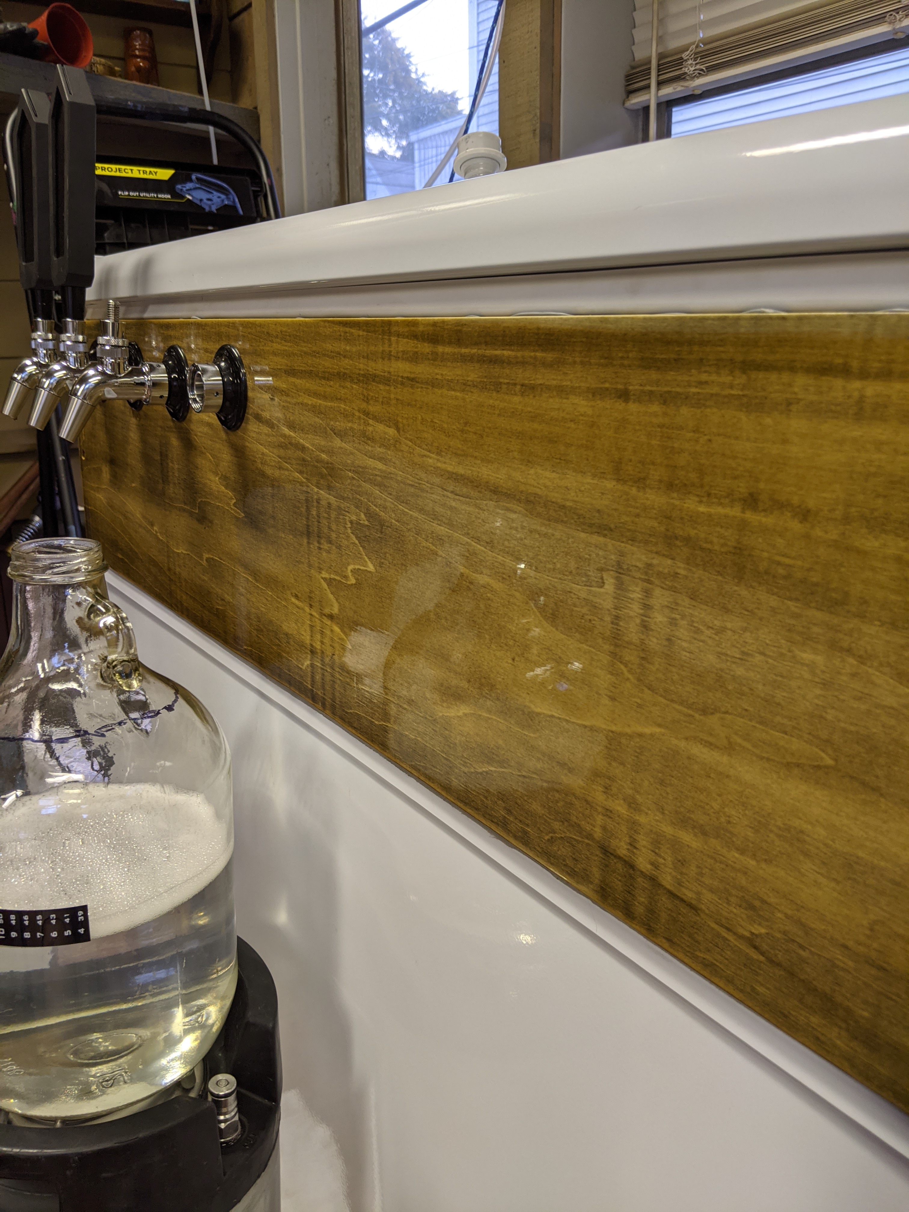
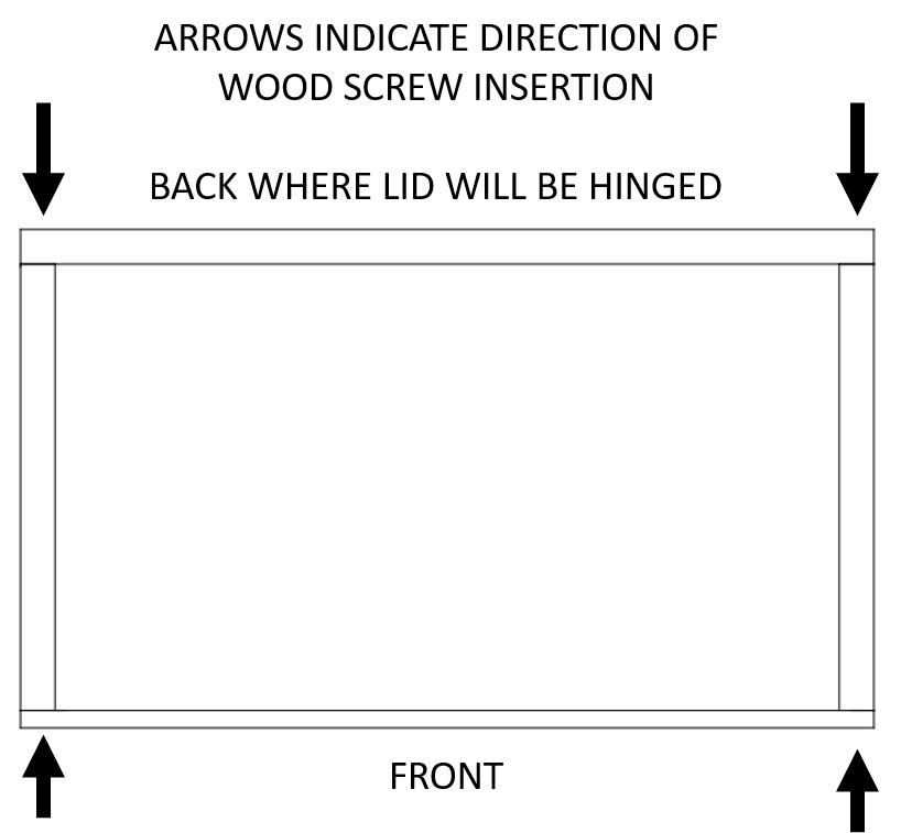
I like the split top for easy loading (26 years of service is finally beating my body apart with a bulging disc), and I like the 1x8 bolted to an inner collar concept, as well - before anyone asks, I'm not sure why, maybe it's the idea of the overhang providing stability for the collar against the body of the freezer (besides liquid nails, what else, when not using a double collar, prevents the collar from sliding backward when you lift the lid?).

However - I'm also considering adding a Rocket Pump for cask ale, and as far as I can tell, that pump has to be mounted on a horizontal surface.

My thought is to cut the front face 1x8 board so that it has an exposed "tail", possibly as long as its width plus thickness (8.75) to which I'd attach a 7.25x7.25 square projecting backwards, attached to the front face - essentially making a four-sided box (front face, extra side panel, top deck, side fascia/collar;

Some futzing around in sketchup (which I just taught myself to use in the last four hours) makes me think that first ofF - combining the doubled collar with the easy-load might result in a LOT of wood to move when lifting the lid.

Hopefully I've figured out how to attach the pictures:
First up is what it looks like with an inner 2x6 collar, with a 3-sided out fascia of 1x8, and a cask box (DC-EL-CB)
Second is just the easy load 2x8 on three sides fronted by a 1x8, with a cask box (EL-CB)
DC-EL-CB.JPG
EL-CB.JPG
 
If you're going for nautical, what about planking the outside of the freezer, making it look like a shipping crate or something. That way your collar can attach to the outside, not the inside.

As for the pump, I've seen plans where there was a small shelf built in along the back wall of the keezer.
 
So, I'm not too interested in completely covering the body of the freezer with anything that would provide insulation on the outer walls.

An inner shelf doesn't really help when I need the handle of the pump to be outside the freezer.

Something like this top mounted pump to start, with an idea to eventually buy or build a swan neck for a fully enclosed beer engine made from the Rocket Pump.
 
So, I've ordered the Hotpoint 7.0 cu ft freezer (backordered til August).

If I've read the online information correctly, the floor is 23 3/4 x 15, the compressor hump is 7 1/2 x 15.
Thanks to the last owner of my house (40+ year union sheet metal worker) I've got soapstone drawing sticks, so I drew those dimensions on my basement floor - looks like, of the used cornys I have, I can only fit four, even with a collar: 1 with a 2' 3.5" circumference, 2 with a 2' 3.75" circ, , 1 with a 2' 4" circ.

That works out to 1 - 8.75" diameter, 2 - 8.83" diameter, 1 - 8.91" diameter.

Now, I've been considering buying Slim Line Torpedo kegs from MoreBeer, in 1.5G and 2.5G, so that I could fit in more than the max 5 gallon cornys my keezer will hold - this revelation cinches that decision.

I've been talking with SWMBConsulted, and I'm looking into fermenting in my corny kegs, and naturally carbonating (especially when I consider making cask ale), so the "fat" 5 gallon kegs will be great fermenting vessels as well storage for transfer to smaller serving kegs.
 
Given the freezer I ordered, I played around in sketchup with what the official external dimensions are (I WILL double check those measurement when it's on the ground, twice!), and using The UrbanOutdoorsMan's easy load configuration,, plus my idea of a side box for a cask pump, here's what I've got so far.

While futzing around I heard my late father's voice in my head while i was measuring pieces for that side box:
"So, you extended the front fascia, which is a 1x8, 7.25 inches so it's square when looked at with the side plate?"
"Yep."
"And the side plate is a 1x8 ripped to a square of 7.25x7.25?"
"Yep."
"So. The top plate, which you're cutting from a 1x8 . . . needs to be 7.25 MINUS .75, by 7.25? Or do you want the front fascia and side plate, when viewed from the right, to be square? Meaning cutting the side plate to be 6.5 inches long . . . and the top plate has be to 6.5 by 6.5? So you not only have to cut the board's length, but rip its width, too? Do you have a table saw?"
"Ye . . . fu . . . .@#$%!!!"
"You could go with the sideplate being full board width high by full board width long - and do the same with the top plate, IF you extend the front fascia length by board width PLUS thickness."
"Hmm."

FRONT_VIEW.JPGLEFT_SIDE_VIEW.JPGRIGHT_SIDE_VIEW.JPGBACK_VIEW.JPGTOP_DOWN.JPGCLOSE-UP_OF_PUMP_MOUNT_FROM_BEHIND.JPG
 
Last edited:
I know. I'm more than willing to take that risk, as I most definitely want to be able to run a beer engine - even if it's one based on the rocket pump for RVs.

Given that I've seen builds that incorporate a set of shelves in the side, this seems like a minor issue.
 
I'm revisiting this.

Not doing the box on the side.

Now what I'm trying to figure out is the best way to connect the four faces.
I'm doing butt joints for simplicity.

My issue is - do I keep my woodscrews parallel - screwing through both front and back boards into the ends of the side board (box 1), or do them 90 degree offset - through the front board into the two side boards, then through the side boards into the back board (box 2)?

I think that because I'm going to be applying some torsion to the back board, having the lid attached to it, that I should aim to reduce withdrawal force on the screws attaching the sides and back to each other, thus, have the side boards long enough to overlap the thickness of the back board, and screw through the sides into the ends of the back (box 2).
 

Attachments

  • BOX1.png
    BOX1.png
    14.9 KB · Views: 34
  • BOX2.png
    BOX2.png
    17.1 KB · Views: 35
And how did you join your collar? I think that's what the OP is going for.

Anyway, the front face will pretty much go along for the ride, so I'd use a full length for that board, overlapping the ends of the side rails.
The back, otoh, will be doing all of the work, and I'm not a fan of screwing into end grain as that's pretty much the weakest option. I'd use a full width back (same as the front) then use pocket screws from the ends of the side rails into the back rail. And if one is equipped to use pocket screws, they can be also used to attach the front to the sides, so no screw heads will show.

All joints should be trued and glued, of course. And while the lid will tend to prevent wracking, corner gussets are never a bad thing...

Cheers!
 
The question is which of the two options provided (and illustrated by the two attachments) to join the four faces of the frame would provide superior strength. So, perhaps describing which option(s) you used might give the OP some confidence - or not :)

Cheers!
 
And how did you join your collar? I think that's what the OP is going for.

Anyway, the front face will pretty much go along for the ride, so I'd use a full length for that board, overlapping the ends of the side rails.
The back, otoh, will be doing all of the work, and I'm not a fan of screwing into end grain as that's pretty much the weakest option. I'd use a full width back (same as the front) then use pocket screws from the ends of the side rails into the back rail. And if one is equipped to use pocket screws, they can be also used to attach the front to the sides, so no screw heads will show.

All joints should be trued and glued, of course. And while the lid will tend to prevent wracking, corner gussets are never a bad thing...

Cheers!
I don't really have the option of doing pocket screws, and I'm looking for simplicity.

I'm going to be using corner clamps, and of course predrilling before putting the screws in, as well as using glue and probably corner gussets.

The way I foresee things, there will be some torsion on the back board, and to avoid stressing the connection, fighting sheering force is easier than fighting withdrawal force.
 
Your drawings show 4 sided. I replied my build was 3 sided. Really unsure how this doesn't help. Thank you.
Actually, your first response DOESN'T say that, and NONE of what you've posted addresses screw directions.

I'm trying to be polite, and I chose not to respond to your first comment, but day trippr said what I would have.

Good day.
 
So one part of the torsion is actually dictated by the hinge resistance, which isn't much. The other part is how the lid rests when fully raised. As an example of that, I have a 6 tap t-tower planted dead center of my keezer lid, and when fully opened the tower is hanging way out beyond the back of the keezer cabinet and effectively keeps the lid open. But that means it's apply torque to the hinge line and its connection to the lid - which would be that back rail on your build...

Cheers!
 
Still wrestling with this (in between applying floor polish coats to my shop floor - which need 30 minutes to dry in between) and honestly given the screw type constraint I still can't offer more than an aesthetics-driven answer. That being, make the front rail full width so you're not looking at the ends of the side rails, then make the back rail sit inside the ends of the side rails so its ends are hidden - again, aesthetics-driven. If gussets are added at the back/side rail corners at least, I don't think it makes much difference in structural strength which way the screws are driven...

Cheers!
 
Are you using dimensional lumber or plywood? If you are using lumber (e.g. 2x6) then having the sides overlap the back, and screwing parallel with the back of the kegerator will give you the best strength. Add some wood glue, and it will make a very strong joint. A half lap , mortise and tenon, or dovetail would be stronger still, but pre-drilled 6 inch long 3/8" lag bolts won't go anywhere. If you are really concerned, you can add some blocks inside the joint and screw in from both directions.

You probably don't need that to attach the front. I would have it completely cover the end grain of the side boards. Glue and some 3" deck screws would be just fine.
 
Last edited:
I'm revisiting this.

Not doing the box on the side.

Now what I'm trying to figure out is the best way to connect the four faces.
I'm doing butt joints for simplicity.

My issue is - do I keep my woodscrews parallel - screwing through both front and back boards into the ends of the side board (box 1), or do them 90 degree offset - through the front board into the two side boards, then through the side boards into the back board (box 2)?

I think that because I'm going to be applying some torsion to the back board, having the lid attached to it, that I should aim to reduce withdrawal force on the screws attaching the sides and back to each other, thus, have the side boards long enough to overlap the thickness of the back board, and screw through the sides into the ends of the back (box 2).

Recommend you use a Kreg Jig & stainless screws. Hidden from the inside, and hold like crazy. Add a dab of wood glue if you feel like it.
 
Recommend you use a Kreg Jig & stainless screws. Hidden from the inside, and hold like crazy. Add a dab of wood glue if you feel like it.

So, in a prior post, I said " I don't really have the option of doing pocket screws, and I'm looking for simplicity."

I also don't care as much about screw heads showing, as I'm aiming for a rustic look - sort of weather and ship beaten to fit with my beachcomber tiki bar theme.

If I ever decide to actually put wood on the body of the body of the freezer, I'm probably going to make it look somewhat like a sea chest - so exposed screw heads will likely end up covered by strips of leather with copper rivets studding them (the rivets are free, left by the last owner of this house).
 
Last edited:
Still wrestling with this (in between applying floor polish coats to my shop floor - which need 30 minutes to dry in between) and honestly given the screw type constraint I still can't offer more than an aesthetics-driven answer. That being, make the front rail full width so you're not looking at the ends of the side rails, then make the back rail sit inside the ends of the side rails so its ends are hidden - again, aesthetics-driven. If gussets are added at the back/side rail corners at least, I don't think it makes much difference in structural strength which way the screws are driven...

Cheers!

Personally I go with this suggestion for the aesthetics. Unless you're planning to add a whole lot of weight to the lid for some reason, the torsion on that back panel is negligible in the grand scheme of things.

In fact, you'll hear from most woodworkers that wood glue is actually stronger than the wood itself. In other words, the wood fibers will break before the glue joint does. I built my collar with only 3/4 inch thick cherry (and foam boards for insulation, but that's not structural) an didn't bother with screws. It's been going strong for over a year now.
 
So, I'm going with the full width front, and the side pieces covering the ends of the back wall as suggested.

Had some issues where even though I measured twice and cut once, I was off, because of blade kerf - specifically on the intersection of the 45° cuts and the board width - twice, I cut into the 9.25" end.

Ended up buying another piece of 2x10.

Found I had to do some thinking to figure out how to clamp the pieces that have a 45° cut on them to the front board, with just what I've got (no swivel clamps).

Solution: use the piece from the other side of that 45° angle to act as a part of the clamp.

Clamp three pieces together - the two that need to be joined and the "negative" of one of them.

One clamp to hold the positive and negative even in the vertical plane, and one to squish negative, positive, and other glued piece together along the horizontal.

Corner clamps top and bottom to hold things square, and an additional horizontal clamp due to slight bowing of the front piece being glued.

Also - 1x10 poplar and a spade bit + a drill jig to ensure 90° drilling don't work as well as I'd hoped, when the shaft of the jig is not faceted, but completely round; two different drills got a little bite, then spun on the jig shaft.

Took multiple stops, reverses, and restarts to get through the board.

The spade bit is extremely aggressive in its cutting and pulling.

But: I've got four holes drilled for tap shanks, and they fit.
 

Attachments

  • IMG_20200902_095612.jpg
    IMG_20200902_095612.jpg
    1.4 MB · Views: 34
  • IMG_20200902_095634.jpg
    IMG_20200902_095634.jpg
    2.9 MB · Views: 36
  • IMG_20200902_101403.jpg
    IMG_20200902_101403.jpg
    2.5 MB · Views: 34
Front section unclamped, back section clamped, unclamped, glued, and quadruple clamped (prototype sides pointed in, so I put a second piece, same size as back wall, up front between the ends of the side boards), and glued.

Set the front section in place to take measurements, I'm just 1/8" too deep, but breaking the bottom front edge should take care of that.
 

Attachments

  • IMG_20200902_163423.jpg
    IMG_20200902_163423.jpg
    1.9 MB · Views: 29
  • IMG_20200902_162207_01.jpg
    IMG_20200902_162207_01.jpg
    2.6 MB · Views: 26
Going for the shipwrecked/Beachcomber look to go with the theme of my eventually tiki patio, first coat of varathane weathered wood accelerator applied to the front section.

I've learned a lot in this project - this time, stain before assembly: my glue mistakes are showing.
 

Attachments

  • IMG_20200902_220511.jpg
    IMG_20200902_220511.jpg
    3.5 MB · Views: 24
Hopefully people are still paying attention to this build.

All the wood is stained and polyurethaned, and dry. I'm just carving my pink foam boards (I hate this stuff).

Looking for a recommendation - glue the back half of the collar to the freezer, THEN glue the pink insulation in, or glue the insulation into the collar before mounting the collar onto the freezer?
 
think I would solve the lumber connection first. That way you can see the whole joint and seal it properly.

Adding the insulation becomes easy to fit as needed with some expanding foam to seal all the oddball areas.
 
think I would solve the lumber connection first. That way you can see the whole joint and seal it properly.

Adding the insulation becomes easy to fit as needed with some expanding foam to seal all the oddball areas.
Well, I decided against expanding foam, but I'm glad I went with your suggestion of mounting the bare wood first.

Still, my angled cuts of the foam edges where they intersection the freezer wall, were way off, they don't match the angle of the inside - but they do touch top and bottom, thanks to taking your advice.

One inch pink foam on the back and sides, two layers of one inch on the front, all that covered with reflectix, and the seams sealed with foil tape.

Just glued the lid to the front part, and I've got over 15 gallons of water sitting on top of it instead of rigging a clamp.
 

Attachments

  • PXL_20200913_173015367.jpg
    PXL_20200913_173015367.jpg
    1.8 MB · Views: 46
Well, I learned something important today.

Leak test items in a safe environment before testing.

Evidently I lost a head gasket for one of my beer faucets.

I found out while trying to run sanitizer though my first two beer taps, on the keezer.

They're cheap, until you factor in shipping.

I'll check LHBS (Local HomeBrew Store) before I order, but I've still got other products I'm looking to order.

In other news, the amber ale I brewed on 1 January, and never got around to bottling?

Tastes great and pours fine from the tap.

The bar is open.

I'll add photos of the inside shortly.
 
Ok, here's the inside.

Instead of a four way manifold or prebuilt secondary regulator, I built a four way secondary out of duotight components and inline secondary regulators.

I bought the regulators before the inline secondary regulators WITH gauges came out. Having played around with the blowtie spunding valve, I'm glad I didn't spend the money on the new gauged inline regulators.

I don't think there's enough precision in those tiny gauges to use where I want accuracy.

So, I built a spunding valve using a digital pressure gauge, and I hook that on the outlet of my inline secondary regulators to dial in the serve pressure.

So I need to keep a screwdriver readily available if I have to tweak something.

Big deal.

I wasn't sure how I was going to mount the four way, because kegland had not yet started selling the polycarbonate project panels they now have.

I had some spare mdf. I primed that and screwed the regulators to it.

Then I added some command strip based hooks rated for 5lbs each, two on the gas panel, two on the inside back wall, and used a split ring key ring between each pair.

Used command hooks to hang the circulation fan (120mm usb powered) on the left inner wall. There it won't get in the way of kegs on the hump.

Intertap faucets with springs installed, and the 4" shanks designed for duotight connection - I like the modularity of their components.

I'm including a close-up photo to show the finish on the front by way of reflection.
 

Attachments

  • PXL_20200918_223743336.jpg
    PXL_20200918_223743336.jpg
    2.8 MB · Views: 62
  • PXL_20200918_222455467.jpg
    PXL_20200918_222455467.jpg
    2.7 MB · Views: 65
  • PXL_20200918_222423726.jpg
    PXL_20200918_222423726.jpg
    3.1 MB · Views: 66
Looks like a cask beer engine from here. Sweet :mug:

Cheers!
It is indeed a beer engine - an Angram CQ model, which I purchased from someone here on HBT.

I was thinking about building a rolling platform and side cabinets for the keezer, and making one of the side cabinets a mount for the engine, but I have since decided against that. It is unlikely I will be serving cask all all the time, and I'm not that good of a woodworker that I'm wil;ling to undertake that project.

I ordered a demand valve (sometimes incorrectly called a check valve) from a store in the UK, which, even with international shipping and the GBP-USD exchange, was less expensive than buying it from an American store.

While they recommend 1/2 in tubing for the beer engines, given that I'm going to serve from a corny keg, which has a much narrower diameter in the liquid out tube, I'm sticking with 9.5mm eva barrier tubing and connections, with a cask breather built from a lpg regulator.

Eventually.
 
Back
Top