240VAC Toolbox Control Panel with Pics

Homebrew Talk - Beer, Wine, Mead, & Cider Brewing Discussion Forum

Help Support Homebrew Talk - Beer, Wine, Mead, & Cider Brewing Discussion Forum:

This site may earn a commission from merchant affiliate links, including eBay, Amazon, and others.
I'm not sure what you consider a steal....the lowest I could find on Ebay for a D2425D is ~$36/unit.

I paid $28 each from a seller named "brinkercontrols". Shipping was $6. They are $64 each on Digikey, so I thought it was a good deal.

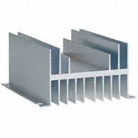
Also, here is the heatsink I used. It has a low thermal resistance ( deg. C per Watt). You can mount 2 normal SSRs on it. Click pic for link to Digikey.


So you went with the 25A SSRD's....has that caused any issues? I guess you're switching 23A, but it IS close.

You say you can mount 2 "normal" SSR's on the heatsink....but you obviously fit 2 SSRD's...any mods?
 
So you went with the 25A SSRD's....has that caused any issues? I guess you're switching 23A, but it IS close.

You say you can mount 2 "normal" SSR's on the heatsink....but you obviously fit 2 SSRD's...any mods?

No problems ever. Not a single one. I've made a lot of beer with this exact system. And no mods. the footprint of these DSSRs is exactly the same as single SSR.

The D2425D datasheet has curves for the power rating for this SSR. The 25A limit assumes a 5.0 C/W heatsink.

The heatsink I show above is 0.7 C/W. I used Arctic Silver 5 to join the heat sink and the SSR. According to the Crydom derating curves, I can drive nearly 50A per section. So, I think it's fine.

An improvement I just thought of: Right now, both 230VAC legs to the HLT go through the same DSSR (and same for the BK). So when the HLT is on, for example, both halves of the same DSSR are getting hot. What I should do is split the legs across the 2 DSSRs so that exactly half of each one is being used, the the heat is spread better across the heat sink. Did that make sense?
 
An improvement I just thought of: Right now, both 230VAC legs to the HLT go through the same DSSR (and same for the BK). So when the HLT is on, for example, both halves of the same DSSR are getting hot. What I should do is split the legs across the 2 DSSRs so that exactly half of each one is being used, the the heat is spread better across the heat sink. Did that make sense?

Yup, that made sense and sounds like a good idea.
 
Yup, that made sense and sounds like a good idea.

Sure, I guess you "criss cross" everything....it makes sense.

But isn't low thermal conductivity a bad thing? Seems like I'd rather have 5C/watt conducted through the heatsink and released into the atmosphere. Or is that bad, because you don't want the heatsink getting too hot?

It seems like a muffin fan with a splashproof intake and exhaust on the box would be easy and really effective. You could put it inline with the accessory 115v receptacle (vs the switched one for the pump) and it could always be on.
 
He's not talking about low conductivity but rather a more distributed production of heat on the sink; One really hot spot vs two not-so-hot spots.
 
So is the general consensus that you should have 2 SSRs per 240v element? One for each leg. Then do you need also 2 PID's per element?
 
So is the general consensus that you should have 2 SSRs per 240v element? One for each leg. Then do you need also 2 PID's per element?

Nope, just 1 PID. You want 2 SSR's or a Dual SSR so you can switch off both hot legs of the element, not just one. With only 1 SSR you still have 120V running through the element when it's "off".
 
Nope, just 1 PID. You want 2 SSR's or a Dual SSR so you can switch off both hot legs of the element, not just one. With only 1 SSR you still have 120V running through the element when it's "off".

that's what I thought. Just send the PID's one output to both SSR inputs then? I have the Auberin PID and 1 SSR for a BK build, but haven't looked at stuff yet. I'll have to pick up another SSR for it.
 
He's not talking about low conductivity but rather a more distributed production of heat on the sink; One really hot spot vs two not-so-hot spots.

I understand the discussion about heat distribution across the heat sink....I guess I was referring to the heat sink C/W "rating" that was mentioned earlier.
 
FYI: you do not *need* to use a second SSR. Some folks prefer it, but some don't.

I have a kill switch that cuts both hot lines going to the element when I want to power it down completely, and I just use one SSR controlled by the PID for the actualy automated heating stuff.

It's a personal preference. Neither way is right or wrong, but both ways have their pros and cons.
 
I totally understand the concept of having 1 ssr for each leg...I guess it's a matter of how you want to integrate safety. Either way is fine, breakers/contactors are nice too. I guess I wonder if you decided to only switch 1 leg and you had multiple elements, would there be a current draw to factor in for the one that was not in use?
 
FYI: you do not *need* to use a second SSR. Some folks prefer it, but some don't.

I have a kill switch that cuts both hot lines going to the element when I want to power it down completely, and I just use one SSR controlled by the PID for the actualy automated heating stuff.

It's a personal preference. Neither way is right or wrong, but both ways have their pros and cons.

Right. I understand the 2nd SSR is thought of as a "safety precaution". Does having 120 through the element constantly effect the performance? You would think the PID want's to shut off the element because you are up to temp, say in an HLT, but the element is still on via 120VAC. So say with a 5500W element, when the it needs to be off to maintain a temp, you'd still have ~2500W running through it, over heating your water?
 
But isn't low thermal conductivity a bad thing? Seems like I'd rather have 5C/watt conducted through the heatsink and released into the atmosphere. Or is that bad, because you don't want the heatsink getting too hot?

Well, maybe that should have been thermal resistance; smaller numbers are better. You take the C/W (degrees C per Watt ) and multiply it times the watts you are trying to disappate, and you easily calculate the temperature rise over ambient. For example, if my SSR is 0.050 ohms, and I running 23A through one leg of it, the the power (watts) = I^2 * R = 23^2 * 0.050 = 26W.

Then, 26W * 0.7 C/W = 19 C (33 degrees F over ambient; if it's 80F, I would measure 113 at the SSR.

Now, since both legs are used at the same time on that SSR, I need to double that, so I would expect to see a 66F rise on the SSR: it would get to about 143F today. In fact, that is very close to what I am seeing.
 
you'd still have ~2500W running through it, over heating your water?

No, the element doesn't work that way. When one leg is cut there is no voltage because you're not completing a circuit. The danger is if you complete the circuit with that 120V running through the element by touching a ground/neutral/hot. (Someone correct me if I'm talking outta my @$$.)
 
Right. I understand the 2nd SSR is thought of as a "safety precaution". Does having 120 through the element constantly effect the performance? You would think the PID want's to shut off the element because you are up to temp, say in an HLT, but the element is still on via 120VAC. So say with a 5500W element, when the it needs to be off to maintain a temp, you'd still have ~2500W running through it, over heating your water?

Nope, you're confusing current and watts. Voltage does nothing; it's the current that creates the heat. by turning off one leg, you have clamped off the current.

If it helps, electrical current is analogous to water flow in a hose. If you step on one end of the hose, there is no flow. The pressure remains, though (pressure = voltage). No flow, no power (watts), no heat.
 
well then I gotta go with walker on this and I'll stick with one SSR but a SPDT switch to cut both legs. (Did I get that right on the Single Pull double throw switch? That always messes me up. I want one toggle to cut two contacts)
 
No, the element doesn't work that way. When one leg is cut there is no voltage because you're not completing a circuit. The danger is if you complete the circuit with that 120V running through the element by touching a ground/neutral/hot. (Someone correct me if I'm talking outta my @$$.)

You are correct.

Electricity needs a complete path to operate. Current must be able to go into the circuit and then come back out. The heating elements are connected to two wires, so cutting one of them breaks the circuit and no current can flow, so no hear is produced.

But, as you say, even though no current is flowing, that one line that is going out to the element (the line NOT going through an SSR) is energized. If you touch it, it will shock you and your GFCI breaker will trip.

I don't touch anything unless I flip the kill switch that cuts both lines compeletely. Even if I was using two SSRs, I wouldn't trust them and would flip a kill switch before I touched anything.

I do, however, trust the large mechanical device that connects or disconnects the wires completely. :D
 
No, the element doesn't work that way. When one leg is cut there is no voltage because you're not completing a circuit. The danger is if you complete the circuit with that 120V running through the element by touching a ground/neutral/hot. (Someone correct me if I'm talking outta my @$$.)

There's still voltage. No current. For the same reason you stated, no circuit.

It helps to consider the water analogy again:

voltage (volts) = pressure, (psi)
current (amps) = flow (gpm)
resistance (?) = resistance (ohms)
The heating potential of an element is rated in Watts. If you are using the voltage recommended for that element, you can calculate the current through it by I = W/V.

I.e., I = 5500W / 240VAC = 23A.​
 
well then I gotta go with walker on this and I'll stick with one SSR but a SPDT switch to cut both legs. (Did I get that right on the Single Pull double throw switch? That always messes me up. I want one toggle to cut two contacts)


Nope.. DPST.

Double pole because you are simultaneously switching two lines.
Single throw because you want to connect or disconnect it.

A SPDT switch would be switching a single wire, but would allow you to connect that single wire to one thing or to another thing.

SPST would switch one wire, but would connect or disconnect it.
 
You are correct.

Electricity needs a complete path to operate. Current must be able to go into the circuit and then come back out. The heating elements are connected to two wires, so cutting one of them breaks the circuit and no current can flow, so no hear is produced.

But, as you say, even though no current is flowing, that one line that is going out to the element (the line NOT going through an SSR) is energized. If you touch it, it will shock you and your GFCI breaker will trip.

I don't touch anything unless I flip the kill switch that cuts both lines compeletely. Even if I was using two SSRs, I wouldn't trust them and would flip a kill switch before I touched anything.

I do, however, trust the large mechanical device that connects or disconnects the wires completely. :D

I myself will be using both a DPST switch and 2 SSR's, maybe I'm overly-cautious, but that's just me.
 
Well, maybe that should have been thermal resistance; smaller numbers are better. You take the C/W (degrees C per Watt ) and multiply it times the watts you are trying to dissipate, and you easily calculate the temperature rise over ambient. For example, if my SSR is 0.050 ohms, and I running 23A through one leg of it, the the power (watts) = I^2 * R = 23^2 * 0.050 = 26W.

Then, 26W * 0.7 C/W = 19 C (33 degrees F over ambient; if it's 80F, I would measure 113 at the SSR.

Now, since both legs are used at the same time on that SSR, I need to double that, so I would expect to see a 66F rise on the SSR: it would get to about 143F today. In fact, that is very close to what I am seeing.

You are absolutely correct. However for clarification sake and to help others calculate power dissipation, the majority of heat is generated by the voltage drop across the device, not the resistance.

typical SSR and thyristors, triacs, whathaveyou have a very low ON resistance...in the neighborhood of 1.0 milliohms. but the voltage drop is around 1.1-1.5V. Do the math with 23A through it you have 25-35W dissipated because of the voltage drop and only 0.5-1W because of resistance. If you stick with 1.5V you'll be worse case when calculating heat.
:mug:
 
Nope.. DPST.

Double pole because you are simultaneously switching two lines.
Single throw because you want to connect or disconnect it.
.

I think my confusion is how I say it. I say it as Double Pull , Pole makes sense d'uh. Believe it or not I do have an electrical background, but it's been about 5 years since I've used any of it short of simple home wiring.
 
I myself will be using both a DPST switch and 2 SSR's, maybe I'm overly-cautious, but that's just me.

That's what I did. Home depot sells 230V 30A DPST switches.

Leviton_30A_240V_DPST_Switch.jpg
 
I myself will be using both a DPST switch and 2 SSR's, maybe I'm overly-cautious, but that's just me.

If you want to be overly cautious, then do you really want to touch a switch that is passing 240V/30A through it? :D (Are your hands ever wet when you brew?)

I actually don't use a DPST switch. I use a 2-pole contactor to do the switching of the 240V lines.

The contactor is triggered with a lower voltage, lower current signal, and THAT signal is the one I mess with with a simple SPST switch.
 
Nope, you're confusing current and watts. Voltage does nothing; it's the current that creates the heat. by turning off one leg, you have clamped off the current.

correct. you don't have 120V at all going to the element...it's only 240V. You open one leg, the other delivers no current.

...well unless you are standing in water with a open cut on your foot and you touch it...then it will do plenty to kill your a$$. :D Hence GFCI breakers, contactors and two SSR's to open both legs of the 240.
 
Hmmm.... maybe $10 - $15

Yeah, that's about right from when I remember. You can find 240V, 30A DPST switches at mouser.com for a little cheaper than $10.

When I looked at 2-pole contactors (which take up a lot of space in the box) I found that the price of a 2-pole contactor and a simple SPST switch was about the same as a big burly 240V,30A DPST switch, so I went for the contactor. Overly cautious and all...
 
I can't find any 30A DPST switches on mouser or automation direct. I must not be looking right. I want industrial panel switches for my control panel.
 
I can't find any 30A DPST switches on mouser or automation direct. I must not be looking right. I want industrial panel switches for my control panel.

Hmmm.. I can't find them on there either... at least not ones rated for 240V. I do see 30A/125V, but not 240V.

I swear to god they had them 6 months ago when I started shopping, but I don't see them anymore.
 
Hmmm.. I can't find them on there either... at least not ones rated for 240V. I do see 30A/125V, but not 240V.

I swear to god they had them 6 months ago when I started shopping, but I don't see them anymore.


IP: mouser's database isn't accurate on everything.

This switch is listed on mouser as 30A/125V:
http://mouser.com/ProductDetail/NKK-Switches/S821-RO/?qs=sGAEpiMZZMvudeGI7i40XGort1gkgk11B7UtCDbC7nY%3d

But if you look at the manufacturer's data sheet, it can handle 30A/250V with a resistive load.
http://www.nkkswitches.com/pdf/stoggleshighcap.pdf

edit: just noticed that this switch is $22. :eek:
Thanks all., I thought I'd gone retarded for a minute :D
 
IP: mouser's database isn't accurate on everything.

This switch is listed on mouser as 30A/125V:
http://mouser.com/ProductDetail/NKK-Switches/S821-RO/?qs=sGAEpiMZZMvudeGI7i40XGort1gkgk11B7UtCDbC7nY%3d

But if you look at the manufacturer's data sheet, it can handle 30A/250V with a resistive load.
http://www.nkkswitches.com/pdf/stoggleshighcap.pdf

edit: just noticed that this switch is $22. :eek:

The little rubber boot that I list on my schematic would probably screw right onto that (I think its a NKK boot).
 

Latest posts

Back
Top