• Please visit and share your knowledge at our sister communities:
  • If you have not, please join our official Homebrewing Facebook Group!

    Homebrewing Facebook Group

110v Recirculating eBIAB 2.5 gallon batches

Homebrew Talk

Help Support Homebrew Talk:

This site may earn a commission from merchant affiliate links, including eBay, Amazon, and others.
Very cool info. Makes me wanna try it :). Does anyone know if this element http://m.grainger.com/mobile/details/?R=15A569 would work? Looks like it draws the same volts and amps, but I am definitely not anyone you want playing with electricity.

3000w seems pretty high for 120v. I'm not an electrician either, but I think that would need a 30 amp breaker! 2000w is the highest I've seen used on 120v. Maybe someone else can chime in.
 
3000w seems pretty high for 120v. I'm not an electrician either, but I think that would need a 30 amp breaker! 2000w is the highest I've seen used on 120v. Maybe someone else can chime in.
You are absolutely correct. A 3000W element on 120V will draw 25A all by itself and requires a 30 amp feed.. A 2000W element on 120V will draw 17A and therefore requires a 20A 120V breaker.
 
I have had several requests for the first diagram (page 1 on this thread) to have an added 2nd element for a 120V system.

So I spent some time making a drawing for that setup. Power is being fed from 2 seperate 20A 120V GFCI outlets. It includes E-Stop that will trip both GFCI outlets at once.

I hope this is of help to thedude00 and others that have requested it.

As always - Click on the image to see a full scale diagram printable on Tabloid paper (11" x 17")


Wishing all the best.

P-J
 
Just out of curiosity (and the fact my wife and daughter hate when I brew in the kitchen) what would a single element system like this cost to put together? This would make brewing in my garage a much or realistic possibility. Unfortunately a propane burner isn't really an option for me.
 
I have had several requests for the first diagram (page 1 on this thread) to have an added 2nd element for a 120V system.

So I spent some time making a drawing for that setup. Power is being fed from 2 seperate 20A 120V GFCI outlets. It includes E-Stop that will trip both GFCI outlets at once.

I hope this is of help to thedude00 and others that have requested it.

As always - Click on the image to see a full scale diagram printable on Tabloid paper (11" x 17")


Wishing all the best.

P-J

:off:

I apologize if I am off topic for this thread but I have a few questions about the switches in the wiring diagram from the previous post. I am also sorry if these questions are a little remedial.

1. I assume that switches 1 and 2 are designed to manually turn on the elements that are wired to each switch. If this is true will switches 1 and 2 turn on the elements even if switch 4, the PID switch, is off?

2. From what I understand about PID control each of them generally has a manual mode. If the PID switch is on but the PID is not in manual mode would switches 1 and 2 control the elements?

3. If the PID switch is off will both of the elements be off regardless of the position of switches 1 and 2?


Thanks in advance for your advice. I am learning so much from these threads and I am getting really close to pinning down exactly what I will want in my upcoming control panel.
 
...

1. I assume that switches 1 and 2 are designed to manually turn on the elements that are wired to each switch. If this is true will switches 1 and 2 turn on the elements even if switch 4, the PID switch, is off?

2. From what I understand about PID control each of them generally has a manual mode. If the PID switch is on but the PID is not in manual mode would switches 1 and 2 control the elements?

3. If the PID switch is off will both of the elements be off regardless of the position of switches 1 and 2?


Thanks in advance for your advice. I am learning so much from these threads and I am getting really close to pinning down exactly what I will want in my upcoming control panel.

Answers:
1) The switches are there to isolate the power being delivered to the kettle. The design is such that very minimal rewiring would be needed to convert the controller to a 240V system. No, it does not turn the element on. The PID controls the power being delivered to the element.

2) The PID controls the power to the element in manual mode & in temperature control mode.

3) Yes they will be off. However, keep in mind that if this controller is converted to 240V power, 120V of the power will be present at the elements even with the PID shut off unless switches 1 & 2 are turned off.

Hope this helps.

P-J
 
Thanks for the bonus drawing P-J! That will definitely help someone, maybe even me if/when I get the urge to upgrade.

Just out of curiosity (and the fact my wife and daughter hate when I brew in the kitchen) what would a single element system like this cost to put together? This would make brewing in my garage a much or realistic possibility. Unfortunately a propane burner isn't really an option for me.

That's the exact reason I built this system, wife and daughter weren't big fans of the house smelling like brew as often as it was. Plus I like to hang out on my back porch. I haven't kept a tally of how much I spent on this, mainly because I don't want to know or the wife to find out! It's not cheap. I would say I have ~ $500 in my system. But I built it with everything I wanted from the beginning rather than upgrading later. You could save a lot going simpler, and a lot of people biab without a pump.
 
Just out of curiosity (and the fact my wife and daughter hate when I brew in the kitchen) what would a single element system like this cost to put together? This would make brewing in my garage a much or realistic possibility. Unfortunately a propane burner isn't really an option for me.

I was planning on building the one element rig I priced out everything kettle,pump,controller so on and it came to around 650 bucks that's with some extra things. With P-J posting the diagram for the 2 element system i am going to build that one. I am expecting the cost will be a bit higher because of the extra stuff need for the second element. Once I figure out the add gear for the controller ill post the price. I also have a break down of all of the prices will post when i get home. (jrb03 dont mean to high jack you thread just want to help out Krieger)
 
I have had several requests for the first diagram (page 1 on this thread) to have an added 2nd element for a 120V system.

So I spent some time making a drawing for that setup. Power is being fed from 2 seperate 20A 120V GFCI outlets. It includes E-Stop that will trip both GFCI outlets at once.

I hope this is of help to thedude00 and others that have requested it.

As always - Click on the image to see a full scale diagram printable on Tabloid paper (11" x 17")


Wishing all the best.

P-J

P-J Thanks bro I appreciate you taking the time to make up the diagram
 
I was planning on building the one element rig I priced out everything kettle,pump,controller so on and it came to around 650 bucks that's with some extra things. With P-J posting the diagram for the 2 element system i am going to build that one. I am expecting the cost will be a bit higher because of the extra stuff need for the second element. Once I figure out the add gear for the controller ill post the price. I also have a break down of all of the prices will post when i get home. (jrb03 dont mean to high jack you thread just want to help out Krieger)

Great info, not a hijack at all. I want to help everyone too. Good luck with your build!
 
Answers:
1) The switches are there to isolate the power being delivered to the kettle. The design is such that very minimal rewiring would be needed to convert the controller to a 240V system. No, it does not turn the element on. The PID controls the power being delivered to the element.

2) The PID controls the power to the element in manual mode & in temperature control mode.

3) Yes they will be off. However, keep in mind that if this controller is converted to 240V power, 120V of the power will be present at the elements even with the PID shut off unless switches 1 & 2 are turned off.

Hope this helps.

P-J

Thanks for the information P-J! Your electrical advice on this forum is making me consider building a basic control panel myself. :mug:

I now understand why you would want to put a switch on the element and the PID. When I build my own system it will be 240v so I should probably have a switch on the element to have the ability to cut off all the power to the element.
 
Here is the break down ..
Kettle
[*]24 Quart bayou classic stainless-stockpot.
http://www.amazon.com/dp/B000FTEQBK/?tag=skimlinks_replacement-20
$68.05
[*] 2 elements
http://www.grainger.com/Grainger/EMERSON-APPLIANCE-SOLUTIONS-Electric-Replacement-2E754?Pid=search
$17.25 X2
[*]Weldless thermometer sight gauge kit
http://www.bargainfittings.com/index.php?route=product/product&path=46&product_id=83
$25.95
[*] 2 Weldless Bulkhead Kit (one for ball valve one for one for lid recirculating)
http://www.bargainfittings.com/index.php?route=product/product&path=46&product_id=178
$16.00 X2
[*]1/2" NPT STREET 90 elbow
http://www.bargainfittings.com/index.php?route=product/product&product_id=120
$5.00
[*]1/2" NPT stainless steel 3 piece ball valve
http://www.bargainfittings.com/index.php?route=product/product&path=36_57&product_id=128
$17.99
[*] 1 1/2" SS Camlock A Style Quick Disconnect
http://www.bargainfittings.com/index.php?route=product/product&path=51_54&product_id=142
$4
[*] 1 1/2" SS Camlock C style fitting Quick Disconnect
http://www.bargainfittings.com/index.php?route=product/product&path=51_54&product_id=135
$6.00
[*] 2 1/2" SS Camlock F style fitting Quick Disconnect
http://www.bargainfittings.com/index.php?route=product/product&path=51_54&product_id=133
$4 X2

Total
201.5

Pump


[*]great breweh
http://greatbreweh.com/Beer_Pump.html
$69.00
[*]1/2" NPT SS 2 piece ball valve
http://www.bargainfittings.com/index.php?route=product/product&path=36_57&product_id=62
$13.99
[*]1/2" SS Camlock A Style Quick Disconnect
http://www.bargainfittings.com/index.php?route=product/product&path=51_54&product_id=142
$3.70
[*]1/2" SS Camlock F style fitting Quick Disconnect
http://www.bargainfittings.com/index.php?route=product/product&path=51_54&product_id=133
$3.99

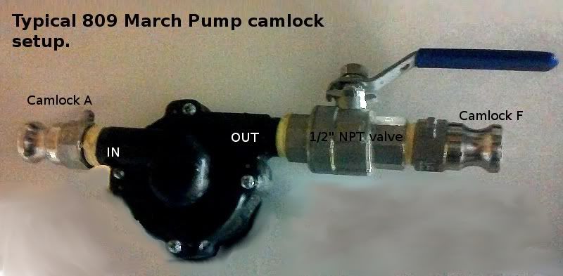
camonpump.jpg


Total 90.69

Control Panel


[*]Project box
http://www.auberins.com/index.php?main_page=product_info&cPath=7_34&products_id=143
$28.67
[*]PID
http://www.auberins.com/index.php?main_page=product_info&cPath=1&products_id=3
$45.50
[*]SSR
http://www.auberins.com/index.php?main_page=product_info&cPath=2_30&products_id=30
$19.00
[*]Heat sink
http://www.auberins.com/index.php?main_page=product_info&cPath=2_30&products_id=244
$12.50
[*] 2 Contactor
http://www.auberins.com/index.php?main_page=product_info&cPath=2_31&products_id=129
$16.00 X2
[*]E-stop
http://www.auberins.com/index.php?main_page=product_info&cPath=7_32&products_id=259
$6.99
[*]Push button switch x3
http://www.auberins.com/index.php?main_page=product_info&cPath=7_32&products_id=223
$11.98 X3
[*]Buzzer alarm
http://www.auberins.com/index.php?main_page=product_info&cPath=7_33&products_id=215
$7.86
[*]Alarm switch
http://www.auberins.com/index.php?main_page=product_info&cPath=7_32&products_id=236
$5.99
[*]Rtd sensor w deluxe cable
http://www.auberins.com/index.php?main_page=product_info&cPath=20_15&products_id=107
$34.00

Total $228.47

Miscellaneous part (wire plugs connectors so on)
Est: total $50.00

Sub Total 570.99

*****tax and shipping not included
***** rounded up in some cases so math may be little off

If you see anything i missed or any place to get supplies for cheaper please let me know
 
Last edited by a moderator:
You will need 2 ssr and heat sinks for 2 elements. Will be pretty tight fitting 2 into the auber project box.
 
You will need 2 ssr and heat sinks for 2 elements. Will be pretty tight fitting 2 into the auber project box.
Ha.! Now is your opportunity to call Suyi Liu, the owner of Auber Instruments (www.auberins.com) and ask for things that are needed for our community (like a larger project box?). He is an outstanding merchant and the owner of the business.

(Drop my name - I suggest 'stuff' all the time.)

P-J
 
Yeah, I thought about emailing him the same thing - a larger project box with the same pre-cut PID opening would be ideal. I'm making a pretty "simple" control panel with one PID for one kettle/element and the room runs out very quickly, especially if you are putting a contactor in there.
 
rack04 said:
What is the purpose of the flash buzzer and the alarm disable switch?

The PID has a built in alarm feature. You can set a high and/or low temp alarm. I use it to alert me when mash in temp is reached. The flash buzzer will blink and beep pretty loud. The switch next to it simply enables and disabled the flash buzzer. It's not a must have, but I'm glad I have it. Especially at its minimal cost.
 
thedude00 said:
The buzzer alarm will go off when you hit your mash temp and the disable switch is just for safety, if something starts to go wrong hit the switch and it will kill power to the control panel.

Ok I get the buzzer but the disable switch is still a mystery. I think what you are referring to is the e stop.
 
Ok I get the buzzer but the disable switch is still a mystery. I think what you are referring to is the e stop.
The alarm disable switch is there to shut off the alarm light/buzzer.

Without the switch in place, you need to change the values within the PID so that the conditions are no longer triggering the alarm. I really believe the switch is a much easier solution than reprogramming the PID on the spot.

Scenario: PID set for strike water temperature. Alarm set to trigger when temp is achieved. (Alarm goes off and a call out goes to you for attention while you are doing other stuff.) Flip the switch and continue with your brew process. Reset PID alarm values at your leisure later on and flip the switch to alert you again when the new event is achieved.

Oh well, I thought it was a good idea so I placed it in the diagram.

P-J
 
Scenario: PID set for strike water temperature. Alarm set to trigger when temp is achieved. (Alarm goes off and a call out goes to you for attention while you are doing other stuff.) Flip the switch and continue with your brew process.P-J

I am excited about this feature! I am planning on setting this kit right on my stove, underneath the venthood. I can already see myself watching football waiting for my strike water to heat up :D
 
Congratulations on the awesome build! I am currently in the "slowly amass bits a pieces" stage of a similar minded system (mash in separate vessel, vis-a-vis jkarp's countertop brutus) and since P-J is on a role with the :eek:nestar:fabulous:eek:nestar: wiring diagrams, I figure I'll try my luck at a blessing as well! ;)

As far as the electronics are concerned, everything would be the same minus the element power leg of the controls. (And using the Auber SYL-2362, but I dont think that changes anything)

I am wondering about the contactor used to switch the element's power. If the system was dedicated to 120V, would this Auber mini relay work for a 2000W element? Secondary to that question, I am planning a little addition on this build's control however. I would like to throw a horizontal float switch into the kettle to prevent dry firing should recirculation become poor and the kettle level drops. Because it has a low amperage switching capacity, I'm assuming it would have to connect to the coil of the relay/contactor. That said, I don't want the float switch to always have control, queue the three position switch!; Such that I can have element power off (says me regardless of anything else on the system), on/off (says the float), or on (says me regardless of float position).

To further complicate things, I am uncontrollably reverting back to my PC-mod days and really would like to have small panel mount LED indicators for things like system power, pump power, element power, and of course water level (do I smell a bicolor high low LED?). Unfortunately and shamefully, I have lost my electrical know-how since those days :(. I'm guessing the drastic change in amperage and voltage will require dusting off the breadboard and making a small project board that interfaces with the status of the control's switches/buttons to feed the diodes.

I would love to start a thread about this build once it gets a little momentum in the physical world. Any help to get the control portion materialized would be great! Thanks everyone, and again congrats on the successful build. :D
 
Last edited by a moderator:
That makes sense. Is there somewhere that explains the pid setting options in manual and automatic?
 
I have received almost all the parts so far, minus the pump.

How long did it take for your pump to arrive after you ordered? I didn't even get a confirmation email from GreatBrewEh. I also emailed them yesterday and they haven't responded. I am hoping this comes in soon as I would will be looking forward to brewing!
 
Sorry for being a noob.. but with the 2 element set up.. i would be able to use those for a 5 gal all grain batch, one in the sparge and one in the boil?? obv 110 setup??
 
You would be able to do a larger batch (~6.5 gal boil) with the two elements in the boil kettle, but you would need two separate circuits to power each element independently; each element connects to different outlets on separate breakers.
 
jrb03,

I see that you have been a member here for several years and I'm honored to be able to answer your first post.

I spent a few hours this morning drawing a diagram that should fit your needs.
The entire build should fit in the Auber Instruments Project Box.

I suggest that you also order their External Mount Heat Sink for the SSR.
The RTD temp probe could be the Deluxe version of Liquid Tight RTD Sensor. It is well worth the extra $9 for it.

I'm not sure how you plan on supplying the 12V power to your pump. I show a 120V outlet that can be used to plug in a transformer. (Edit: I did a search on greatbreweh and found their pumps. They ship with a 12V plug in transformer so the diagram is good to go for that as well.)

I hope this is of some help to you.


As always - Click on the image to see a full scale diagram printable on Tabloid paper (11" x 17")


Wishing you the best.

P-J

P-J you are quite a person to do that. Lots of good people here but a few seem to go above and beyond...such as yourself.

If I had a 'Nice Guy' award I would give it to you.

Ray
 
I have received almost all the parts so far, minus the pump.

How long did it take for your pump to arrive after you ordered? I didn't even get a confirmation email from GreatBrewEh. I also emailed them yesterday and they haven't responded. I am hoping this comes in soon as I would will be looking forward to brewing!

I bought my great brew eh pump from a member of this forum that had an extra for sale. I have read that their customer service has room for improvement, but everyone is receiving their pumps.
 
Back
Top