IS 30A enough for my control panel or am I too close?

Homebrew Talk - Beer, Wine, Mead, & Cider Brewing Discussion Forum

Help Support Homebrew Talk - Beer, Wine, Mead, & Cider Brewing Discussion Forum:

This site may earn a commission from merchant affiliate links, including eBay, Amazon, and others.
So, what's the general feeling on a subpanel versus just using a distribution block? The block is much smaller and I've almost convinced myself that the subpanel is not needed.
 
I'm no electrican but that setup makes sense to me. The only typo I see is that the wire to the elements is 10/3 not 10/4 (there's no need for a neutral). You can use 10/4 wire if you want, just cap the neutral with a marret.
I already have 25' of 10/4 so I will use half to go from the wall to the control panel and the other half from the control panel to the burner. If I didn't already have the 10/4, I agree, 10/3 is what I should use.
 
I'm only using a sub panel because I have a 50 amp gfci breaker in the house panel and I didn't want to use 6 gauge wire everywhere the 220 went. I may not have had to but the sub panel wasn't that expensive and I already had a regular 30 amp breaker for the sub panel. I can also add a 120 v breaker to the subpanel and it will be protected by the gfci as well.
 
I'd go even further and ask what the consensus is on large wire nuts vs distribution blocks?

I used large (to code) nuts on some 6 guage in my basement (inside a box, etc), but that takes up a lot of room, IMO, in a "control panel." Of course, I used wirenuts inside my rig for all the 120V stuff.
 
I didn't want to use 6 gauge wire everywhere the 220 went. I may not have had to but the sub panel wasn't that expensive and I already had a regular 30 amp breaker for the sub panel. I can also add a 120 v breaker to the subpanel and it will be protected by the gfci as well.

In a distribution block, your "out" wire doesn't (and usually isn't) the same size as your out wire.

Also, as far as 120V is concerned, wouldn't you just connect it to one hot instead of two on the block? (Assuming a 3 pole block - 2 hot, 1 neutral)

The Pol, is that how you did yours?
 
I can see by the discussion that there is no real plan. I would suggest an electrical contractor be consulted for the best design of all your wiring. If you choose the wrong plan you may end up spending twice the money by having to change out anything that does not work well. Every person that keeps saying that I am no electrician should not be giving advise when they have no idea what is available or needed (to code). It is better to not find yourself fried on the floor by the paramedics the next day.
 
at work today, i had to go check out a 30 amp disconnect own of my coworkers had installed for a big battery charger. here's the specs on it.
pic5.jpg

the fuse pullout was melted together and i couldn't get the fuse out.
pic3.jpg

the one next to it had a rating of 28 and the disconnect was fine
pic2.jpg

and they' were both inspected and passed by new orleans inspecter, steve bordelon. the one that burnt, was a fault of my coworker carelessly stripping stranded wire. 10 gauge stranded wire don't work so well if u cut half of the strands off...
 
Every person that keeps saying that I am no electrician should not be giving advise when they have no idea what is available or needed (to code).

For the record: there is basically no way to build an electric brew rig to code. We are building (or have built) hot water heaters. However, it's not very hard to wire from main box to the receptacle to code - a basic wiring book has that in it, as well as subpanels, etc. You can actually read the real codes as well (I did for parts of it.) Actually on the brew rig, we can give advice on what has work and should work based on other electrical wiring principles and how other "to code" wiring implementations might be done. In the end, it's just unprofessional advice

That's the disclaimer. Electricity can kill you. Never ever do anything that's not to code. My posts should never be followed and are for reference only.

If you need to hire an electrical contractor or engineer to tell you not build an electric brew rig (because, legally, that's what they should do), then please do. However, if you have issues running a basic 30A circuit, you can hire that out, but I'd recommend you seriously reconsider going electric. If you have trouble with a pretty simple 240V circuit, then you probably don't need to screw around with SSR's and 5400W heater elements.

There, does that make you happy?
 
"legaly" you could actually get a brew rig to "code" and get it passed by an inspecter.... the electrical equipment would for the most part have to be stationary and built into the house, but it would basically be considered an appliance..... i seriously doubt anyone here has tried to get there brew rig inspected.. good idea tho... i will submit a brew rig diagram and i bet i can get it passed. who wants to make a bet? all depends on the "authority having jurisdiction" it wud be up to him to decide if he would pass my brew rig because it's not UL and all that jazz...

mcguires pub in destin fla has a nice electric brew rig but i'm sure it cost a chunk. and i'm sure they had to get it inspected cuz it's in the resteraunt.
pic6.jpg
 
but it would basically be considered an appliance..... i will submit a brew rig diagram and i bet i can get it passed.

Appliances are usually UL approved. (Some places of business refuse non UL approved stuff at the dock, which is a pain in IT...) But, hey, if it could be approved, that would be interesting.

Still wondering about distribution block vs sub panel. I'm thinking of redoing my rig into a 1 tier and would like to shove all the electrical stuff into a single junction box, but the subpanel is just too big.
 
Sorry, maybe marret is a Canadian term. (Like back bacon, tuque, or "eh?"). :)

It's a wire connector/cap:

6309306.jpg


In use:

undercabinet-lighting-9l.jpg


Kal
 
For the record: there is basically no way to build an electric brew rig to code. We are building (or have built) hot water heaters. However, it's not very hard to wire from main box to the receptacle to code - a basic wiring book has that in it, as well as subpanels, etc. You can actually read the real codes as well (I did for parts of it.) Actually on the brew rig, we can give advice on what has work and should work based on other electrical wiring principles and how other "to code" wiring implementations might be done. In the end, it's just unprofessional advice

That's the disclaimer. Electricity can kill you. Never ever do anything that's not to code. My posts should never be followed and are for reference only.

If you need to hire an electrical contractor or engineer to tell you not build an electric brew rig (because, legally, that's what they should do), then please do. However, if you have issues running a basic 30A circuit, you can hire that out, but I'd recommend you seriously reconsider going electric. If you have trouble with a pretty simple 240V circuit, then you probably don't need to screw around with SSR's and 5400W heater elements.

There, does that make you happy?

All I was trying to say here is get someone with electronic experience to help with the engineering of the circuits if you have very little ability with electronics. I am not saying you can not learn but having good help saves time and money and ensures safety in general. There are many ways to do something and some are better than others.
 
Why is it such a bad thing to have one leg still hot to the element?

I'll have my kettle well grounded, and I've always used a plastic spoon.

I guess my question is that if touching the element would cause me to become the easiest path for current... why wouldn't it constantly trip the breaker since the easiest path for it would be through the wort and into the kettle which is grounded?

I can only imagine that means that the element itself won't shock me if one leg is hot, but instead has coatings on it to keep the current away from the water even with one leg still on.

I will have a switch that turns off both legs when I'm done with it, and then I'll also be turning off the breaker when not brewing.
 
All I was trying to say here is get someone with electronic experience to help with the engineering of the circuits if you have very little ability with electronics.

I understand. My comments were not meant to be pointed. I'd take it a step further and say that if you are unsure about it, then don't do it. It's just not worth the risk. If you have electrical knowledge and just need help translating to brewing, that's fine. Not that I'm any master of things, but I read books etc to learn how to wire my basement to code (it was an empty shell). This included subpanels, range outlets (full kitchen in basement - by code that's multiple GFCI circuits, etc.). After that, I felt comfortable around electrical stuff and just needed help understanding PID's, SSR's etc. I ran a few things by a coworker (who is a facilities guy) and built my rig.

So, I think I agree with your comments in general, but was just saying that a good DIY "electrician" shouldn't have any issues with an electric brew cart. However, it should not be your first electrical project, especially if you have not dealt with 240V (2 hots) or GFCI stuff before.

I'm sure someone will post that this was their first electrical project and it turned out great. Hats off to you. Electricity scared the crap out of me until I learned "the rules" about it. (Still have great respect around it though...)
 
I went on a semi-rant about this in another thread:

https://www.homebrewtalk.com/f11/bl...rms-conversion-93217/index14.html#post1036288

Basically, use a DPST switch on the element circuit and turn it off when you want element to be completely off.

I used the DPST switch to cut both legs for one reason only... I wanted to. It assures me that no matter what the PID is doing, the element, outlet... whatever, is totally without power, and I wanted to have a sure fire way to turn it off completely.
I understand that if it is safe to run it with BOTH legs hot, one leg hot is not a big deal. I also understand that it wont heat with ONE leg hot... again, it is just nice to be able to switch off power to that outlet completely.
 
I'm thinking of doing the following:

*Regular* 30A 2-pole breaker in the panel -> 10/4 wire -> some sort of 'disconnect switch' to power the brew panel on/off -> 30A dryer outlet.

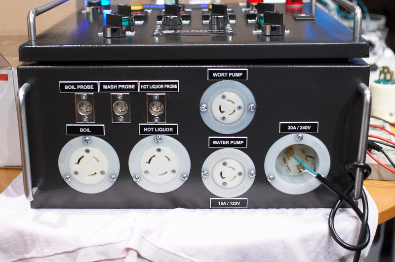
The brew panel will be plugged into the dryer outlet using this 30A/240V 2-pole 4-wire GFI cord to provide protection:

30ampGFI.jpg


$80 off ebay: 30A Ground Fault Interrupt Plug GFI CordCable FREE SHIP - eBay (item 110302613578 end time Jan-19-09 10:23:22 PST)

It's pretty inexpensive. Anyone ever use one of these? They don't mention if it's a "Class A" GFI. That's about my only concern.

One of the nice things about putting the GFI in the cable is that I can then take my brew setup with me elsewhere as we have 'brew day' events around here. 30A dryer outlets are easy to find.

Kal

Got this 30A GFI cable today. The thing is *MASSIVE*. I had concerns about the build quality as it was hard to tell from the pictures but the cord shielding is super-thick and the actual GFI module is almost a FOOT long. It's huge the whole thing weighs almost 8 lbs.

Kal
 
Got this 30A GFI cable today. The thing is *MASSIVE*. I had concerns about the build quality as it was hard to tell from the pictures but the cord shielding is super-thick and the actual GFI module is almost a FOOT long. It's huge the whole thing weighs almost 8 lbs.

I was looking for a cheaper, more portable alternative to buying a GFI breaker...Excellent find! I ordered mine today.
 
Ya I know its an old thread, blame lamara for bringing it back to the top. I noticed when you spec your pumps you stated 1.2 amp ea. This is a running amperage, start up could take 3-6 times as much to get them spinning. Probably closer to 3 amp. So figure 4 amps for each pump when doing you calculations.
 
So I've done a batch now on my setup with one 5500W element going as well as both March pumps and the various lights/PIDs/etc. Total current draw is less than 23A with everything runnning because the voltage is never exactly 240V - it's typically more like 230-232V.

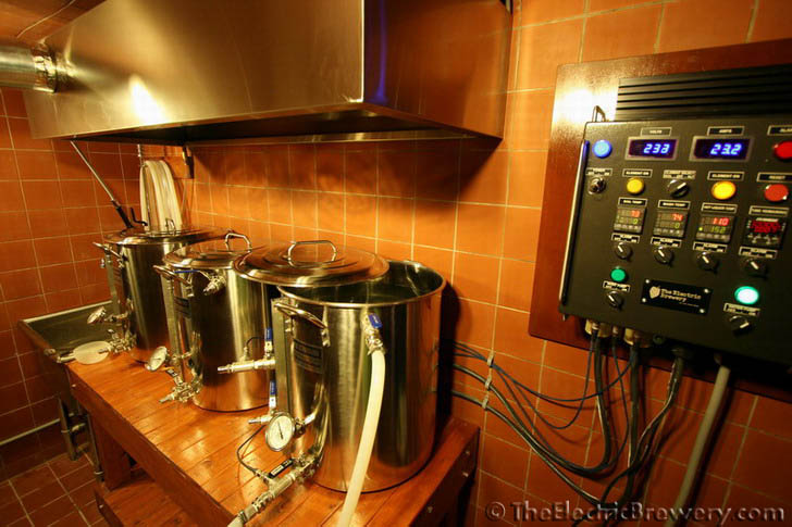
Here's the strike water heating up:

IMG_3387.jpg


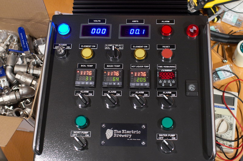
You can see that the voltage is 232-233V (it changed as the camera took the picture) and total current draw is 23.2A. This is one 5500W element running at 100% (manual PID mode) and one pump. With the second pump also running the current draw only goes up slightly.

Building for a 30A service lets me build something portable as 30A dryer outlets are easy to come by. My GFI is on the cord too so it's truly portable.

Kal
 

Nice finish work and I love the Blichmann kettles! :cool:

Where did you purchase the AC ammeter and voltage gauges? I looked around on Ebay a while back and mainly found DC ammeter gauges.

Building for a 30A service lets me build something portable as 30A dryer outlets are easy to come by. My GFI is on the cord too so it's truly portable.

I went the same route (30A inline GFI cable), but I'm not sure I'd call it "portable". The plug won't fit most of the 30a 240v outlets in my area.
 
Nice finish work and I love the Blichmann kettles! :cool:

Where did you purchase the AC ammeter and voltage gauges? I looked around on Ebay a while back and mainly found DC ammeter gauges.
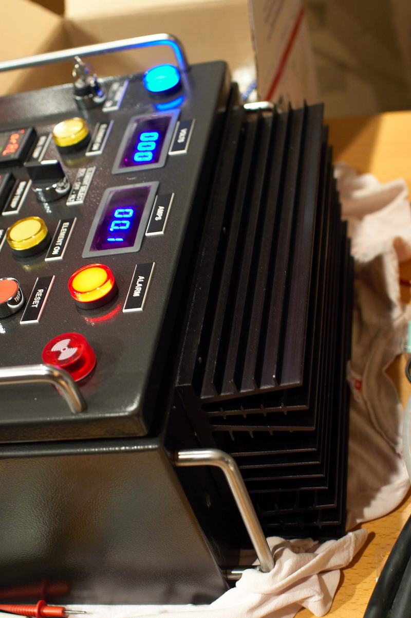
Ebay! Actually, 90% of the control panel was puchased off ebay including the case, heat sink, all switches, buttons, digital timer, relays, etc. The PIDs and SSRs were from Auberins.com

Here's the AC Ammeter: 3½ Digital Blue LED AC 0~50A Amp Panel Meter + Shunt - eBay (item 380144952148 end time Aug-31-09 05:34:58 PDT)

If the auction's gone search for: 3½ Digital Blue LED AC 0~50A Amp Panel Meter + Shunt

Here's the AC voltmeter: 3 Digital Blue LED AC 0~700V Volt Panel Meter New - eBay (item 390084791283 end time Sep-20-09 22:36:19 PDT)

If the auction's gone search for: 3 Digital Blue LED AC 0~700V Volt Panel Meter

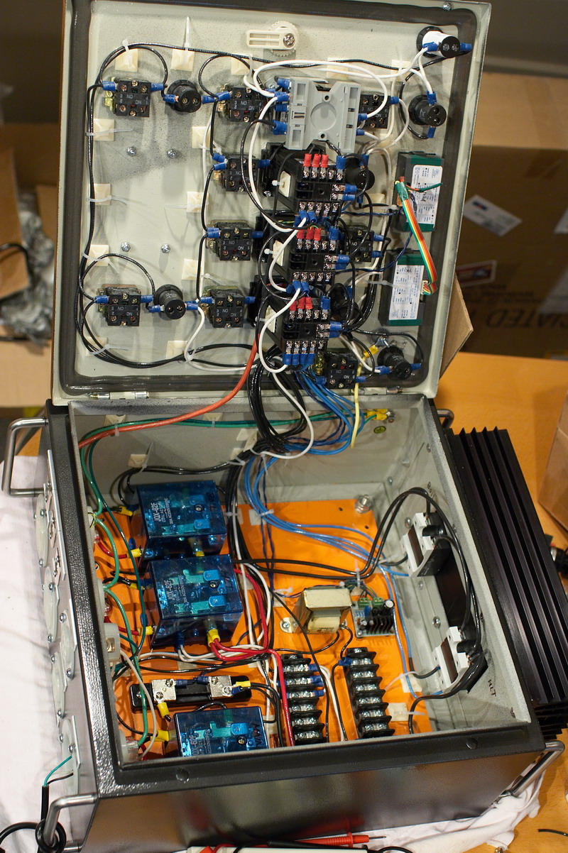
A hint: USE SEPARATE POWER SUPPLIES TO POWER THEM! I tested them both separately first and they worked great but then I blew both of them the first time I hooked them both up to a common 5V power supply because they have one AC line pinned to DC GND on the ammeter! The manual says nothing about this and even says you can use a shared power supply. They sent me new ones. What a pain.

I used two of these tiny power supplies: http://cgi.ebay.com/LM317-In-DC-or-...in_0?hash=item56349acebe&_trksid=p3286.c0.m14

Search for: LM317 In DC or AC 4V-30V Out DC 1.5V-27V 1A Converter

They're variable so that you can adjust the display brightness to match the other displays. Two step-down transformers should be used too. Here's a picture inside back when I only had one 120V->10V step-down transformer and power supply (near the top middle of the backplane):

IMG_1478.jpg


More closeups:

IMG_1475.jpg

IMG_1476.jpg


(The power connection in the above photo is for testing purposes only...) :)

IMG_1477.jpg


I went the same route (30A inline GFI cable), but I'm not sure I'd call it "portable". The plug won't fit most of the 30a 240v outlets in my area.
Strange. It's a standard 240v/30A dryer plug. Fits in my dryer outlet and every other dryer outlet I've seen sold at Home Depot or other electrical stores. If your house is older or not in North America it may be different.

Standard 30A/240V dryer outlet:

dryer-outlet.gif


Kal
 
Looks like you put a lot of time and energy into selecting the components and designing/building the rig. Very impressive. :)

Here's the AC Ammeter: 3½ Digital Blue LED AC 0~50A Amp Panel Meter + Shunt - eBay (item 380144952148 end time Aug-31-09 05:34:58 PDT)

If the auction's gone search for: 3½ Digital Blue LED AC 0~50A Amp Panel Meter + Shunt

Thanks, that's what I was looking for! Since you're measuring total system amperage (120v and 240v components), I assume you installed the shunt in series with the shared "hot" leg, correct?
 
Looks like you put a lot of time and energy into selecting the components and designing/building the rig. Very impressive. :)

Thanks!

Thanks, that's what I was looking for! Since you're measuring total system amperage (120v and 240v components), I assume you installed the shunt in series with the shared "hot" leg, correct?
That's right. There are two 120V hot legs, one neutral, and a ground. Everything goes through one of the hots and then if it's a 120V item it returns across the neutral. If it's one of the two heater elements it returns across the other hot to get 240V total.

Kal
 
Kal I love your setup! Very detailed and very well done. I like that you even have great labels on everything.
Thanks! The labels are easy ... just about any trophy shop or engraving shop will sell them to you for about $1/each.

While the user of the system probably knows exactly what everything does, it just looks completely wrong to have a bunch of lights/dials/controls with absolutely no labels on it. (At least it does to me)

Kal
 
Kal,
To answer the subject of the thread, you ended up going with the 30A circuit correct?
Have you had any problems?

I'm looking at 4500W heater with 2.4A pump running concurrently.
I really like your system including the venting...
 
Kal,
To answer the subject of the thread, you ended up going with the 30A circuit correct?
Have you had any problems?

I'm looking at 4500W heater with 2.4A pump running concurrently.
I really like your system including the venting...
No problems at all. I pull 22-23A with the 5500W element running at 100% and two March pumps and all my dials/switches. So I'm fine.

Kal
 
What's the wire size you are using.
Not sure what wire you're referring to or if the question's directed at me, but for the 30A 240VAC line going between the electrical panel breaker and my control panel which distributes the power, I'm using 10/3 with ground (sometimes called 10/4). This is to code. Anything smaller would be a violation of code and dangerous.

Kal
 
Back
Top