The Beer Robot: BCS-462, Single Tier, eHERMS, two pumps

Homebrew Talk - Beer, Wine, Mead, & Cider Brewing Discussion Forum

Help Support Homebrew Talk - Beer, Wine, Mead, & Cider Brewing Discussion Forum:

This site may earn a commission from merchant affiliate links, including eBay, Amazon, and others.

Denny330

Well-Known Member
Joined
Apr 9, 2010
Messages
117
Reaction score
3
Location
America's Cow Hell
I have been designing this in my head and on paper for over six months and finally decided to take the plunge and build it. This is an ongoing project so the updates will probably be slow coming, but I hope to have everything fully operational by the AHA Big Brew Day on May 5 so my Homebrew Club will have a place to brew.

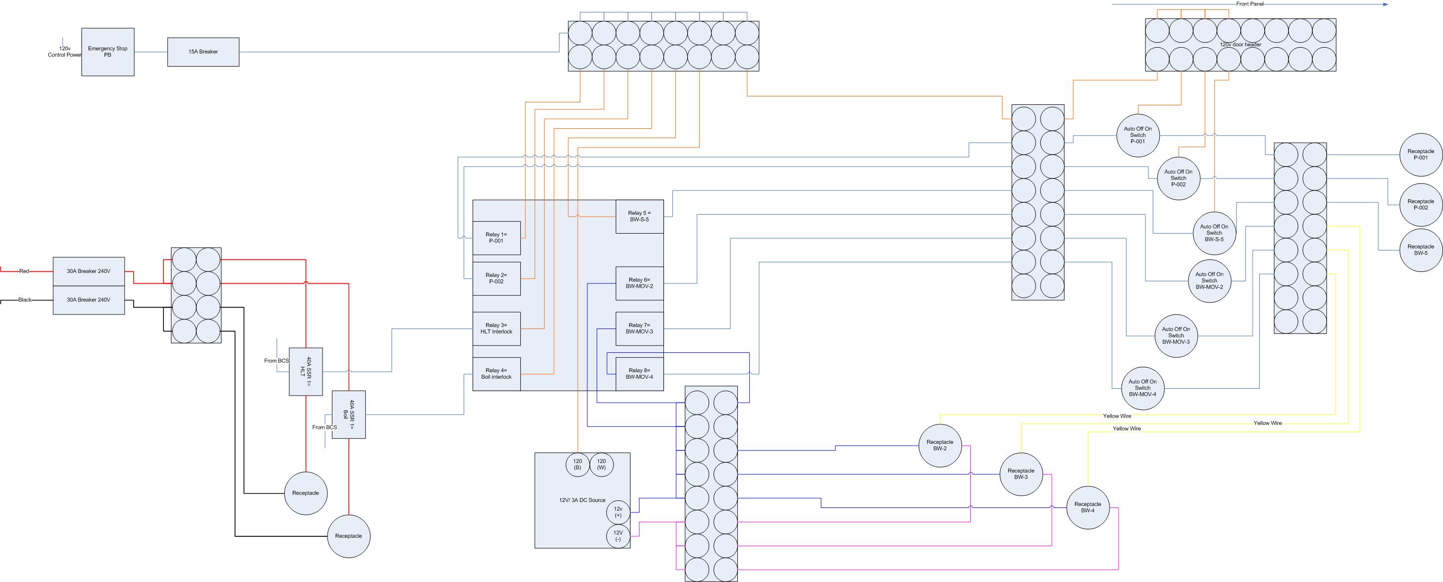
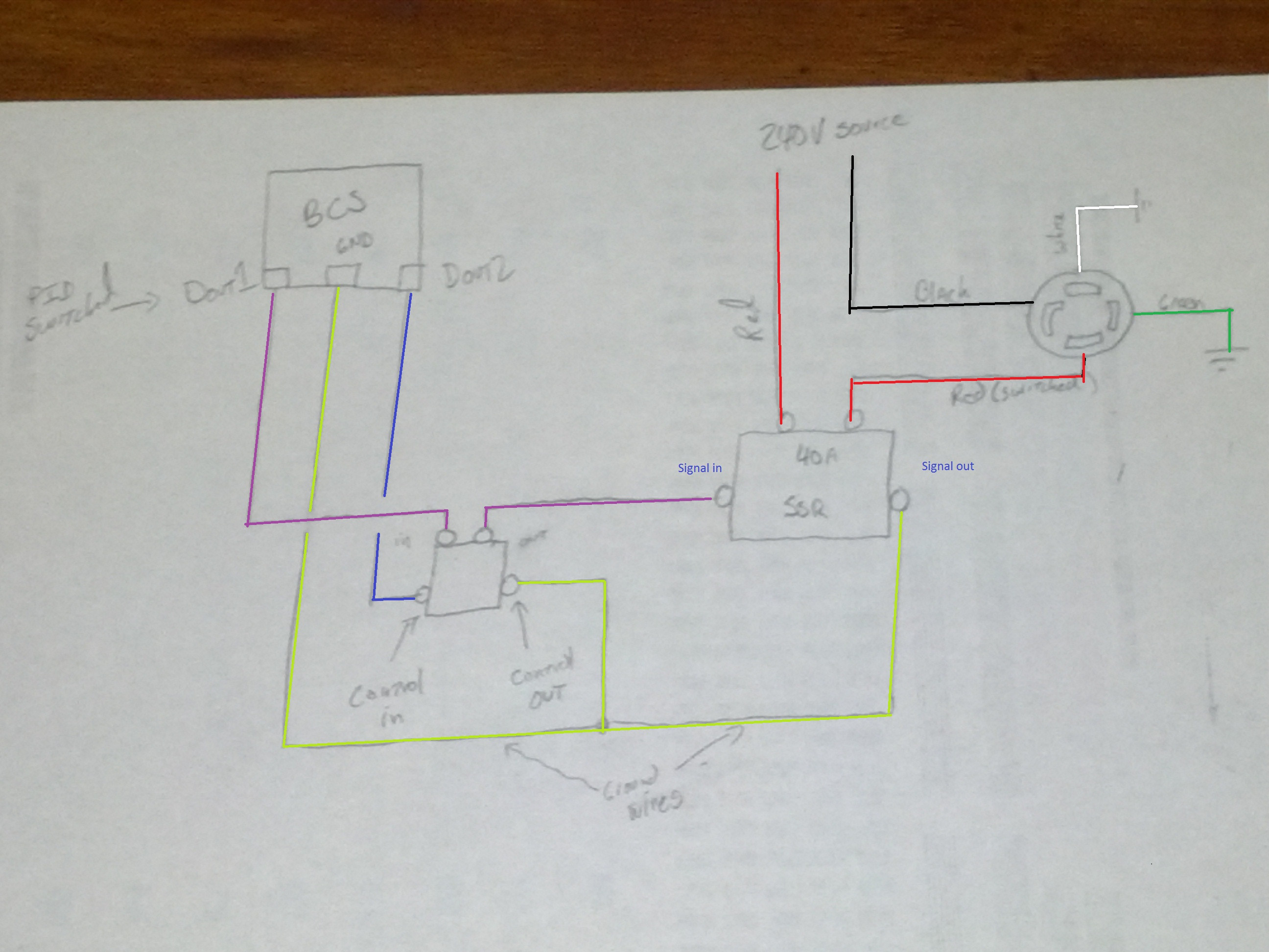
First a little background. I was an electrician in the Navy and currently operate a commercial nuclear power plant, so I know about wiring and diagrams and overdesigning everything, but I don't remember too much from the NEC and I stopped paying attention to the NEC in 1997. If anyone sees anything dangerous or silly that I am doing, please for the love of all things holy tell me. Everyone knows how easy it is to overlook something after you have looked at it for months. I have a visio drawing of my wiring diagram, but I'll figure out how to post it up soon.

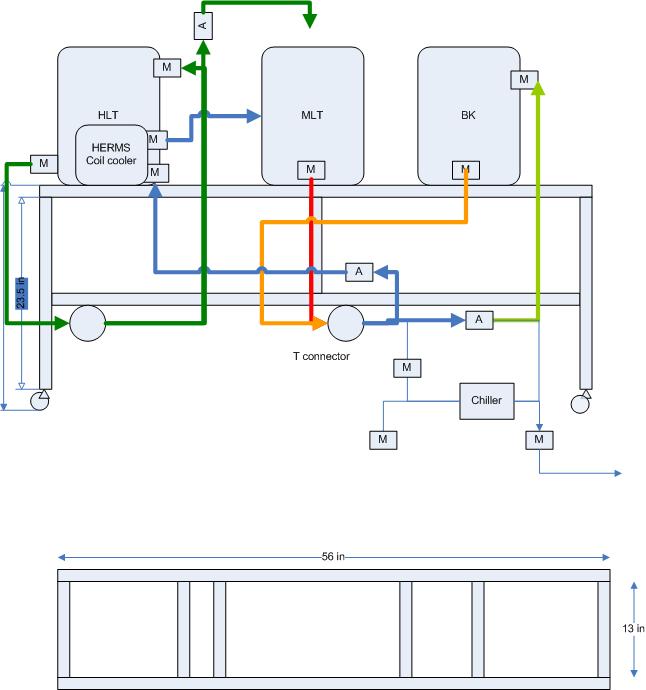
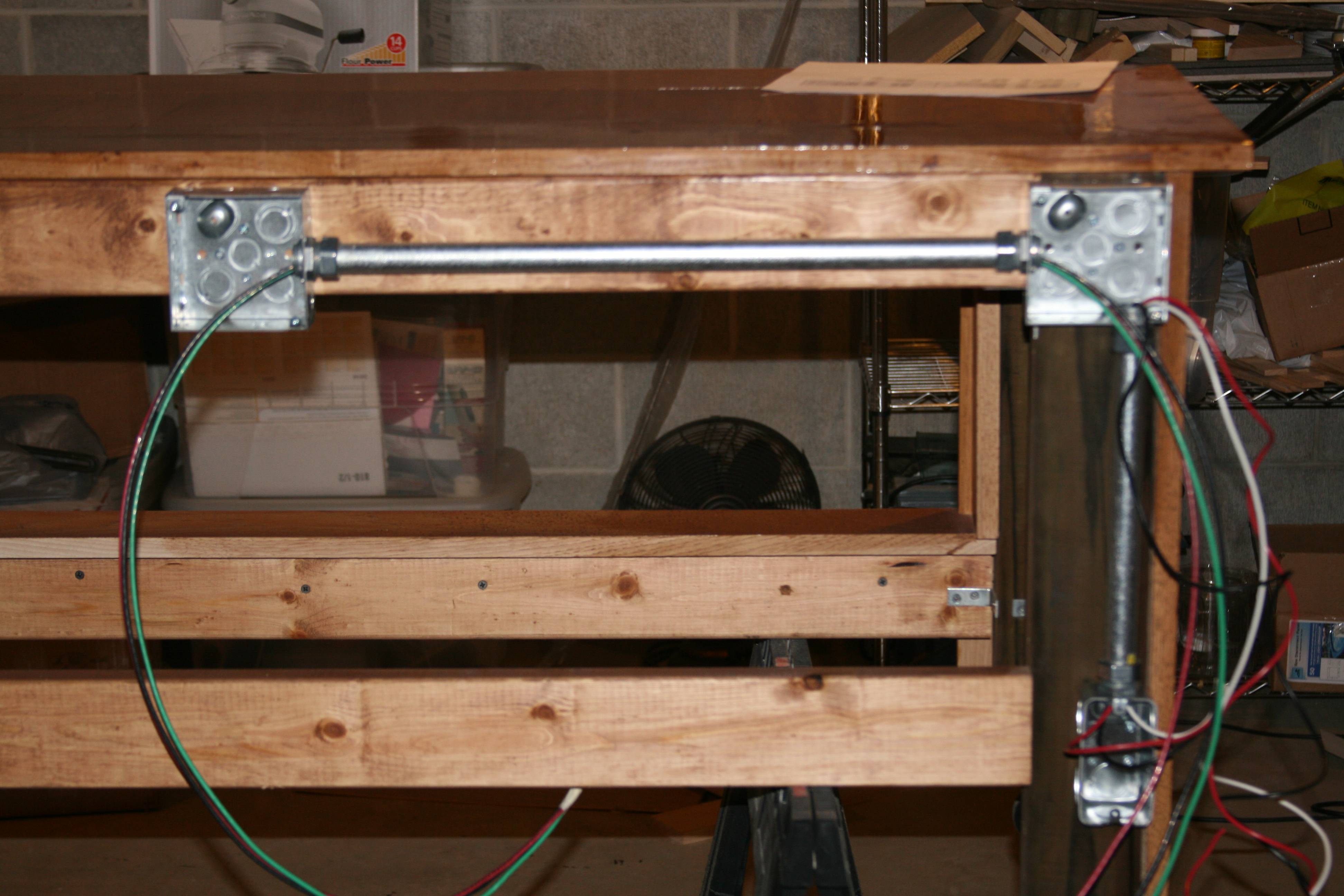
I have a separate thread for the stand if anyone is interested in that: Beer Robot Stand

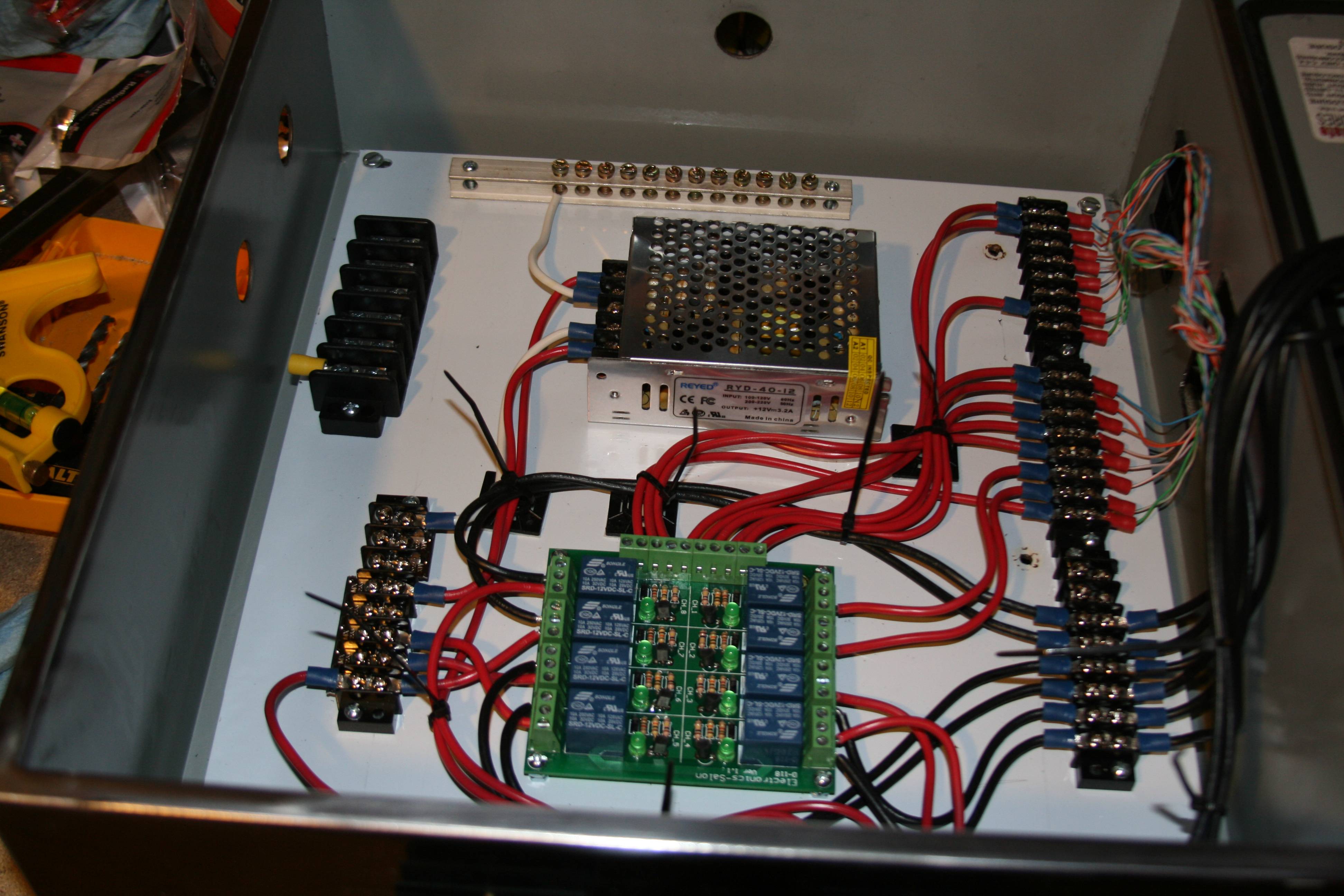
The Beer Robot is an eHERMS design, 5500w element in the BK, 4500w element in the HLT, two chugger pump system, controlling 4 valves, all using the BCS-462 from Embedded Control Concepts. I had planned on using solenoid operated diaphragm valves until yesterday when I found others using these motor operated ball valves. So now I am going to have a 12v component of my control box. (Back to the design drawing board! :mug:)

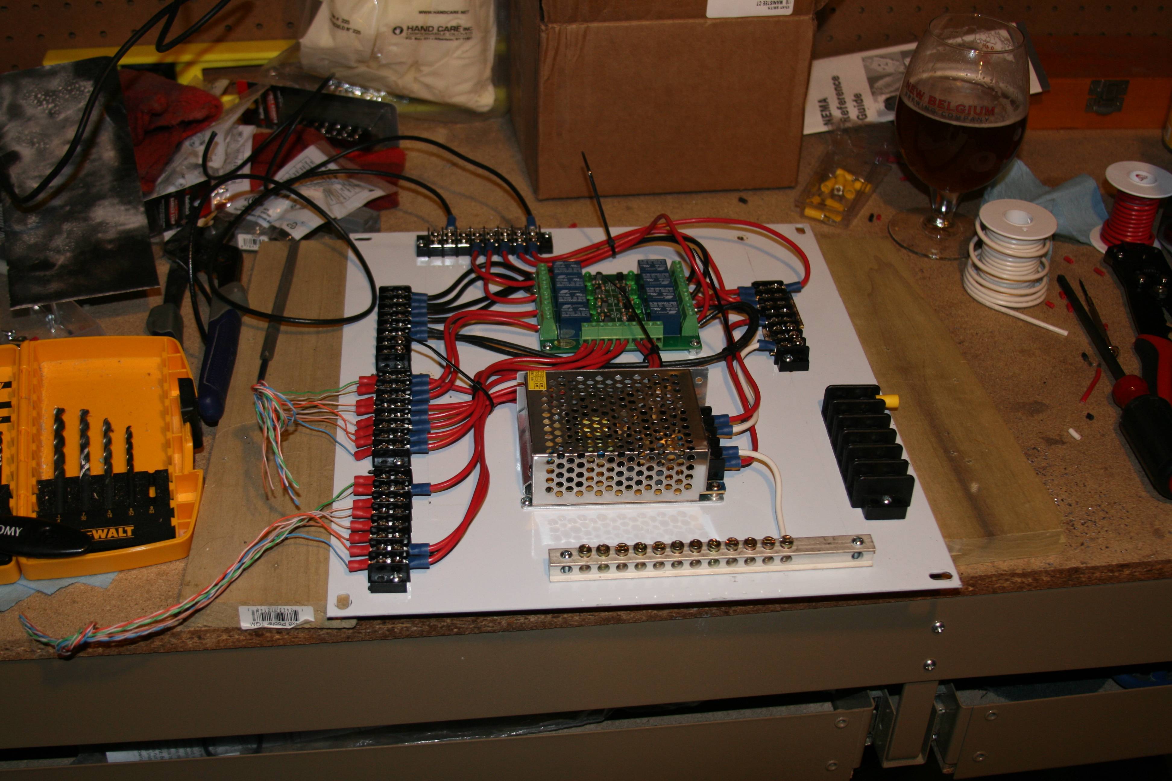
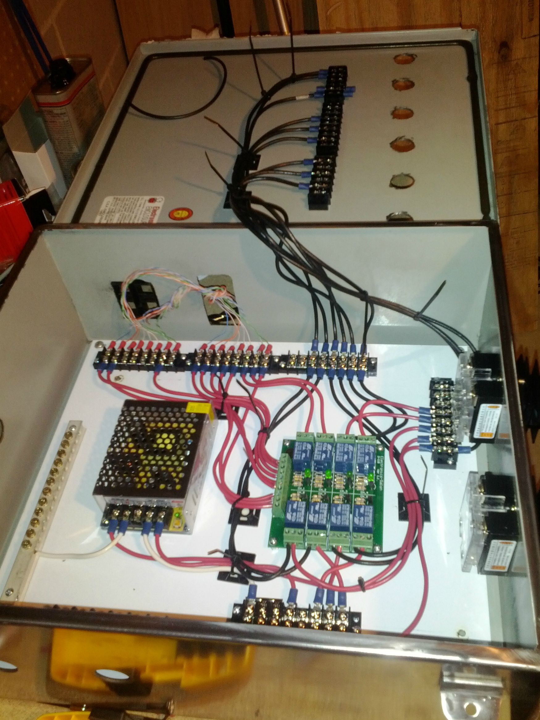
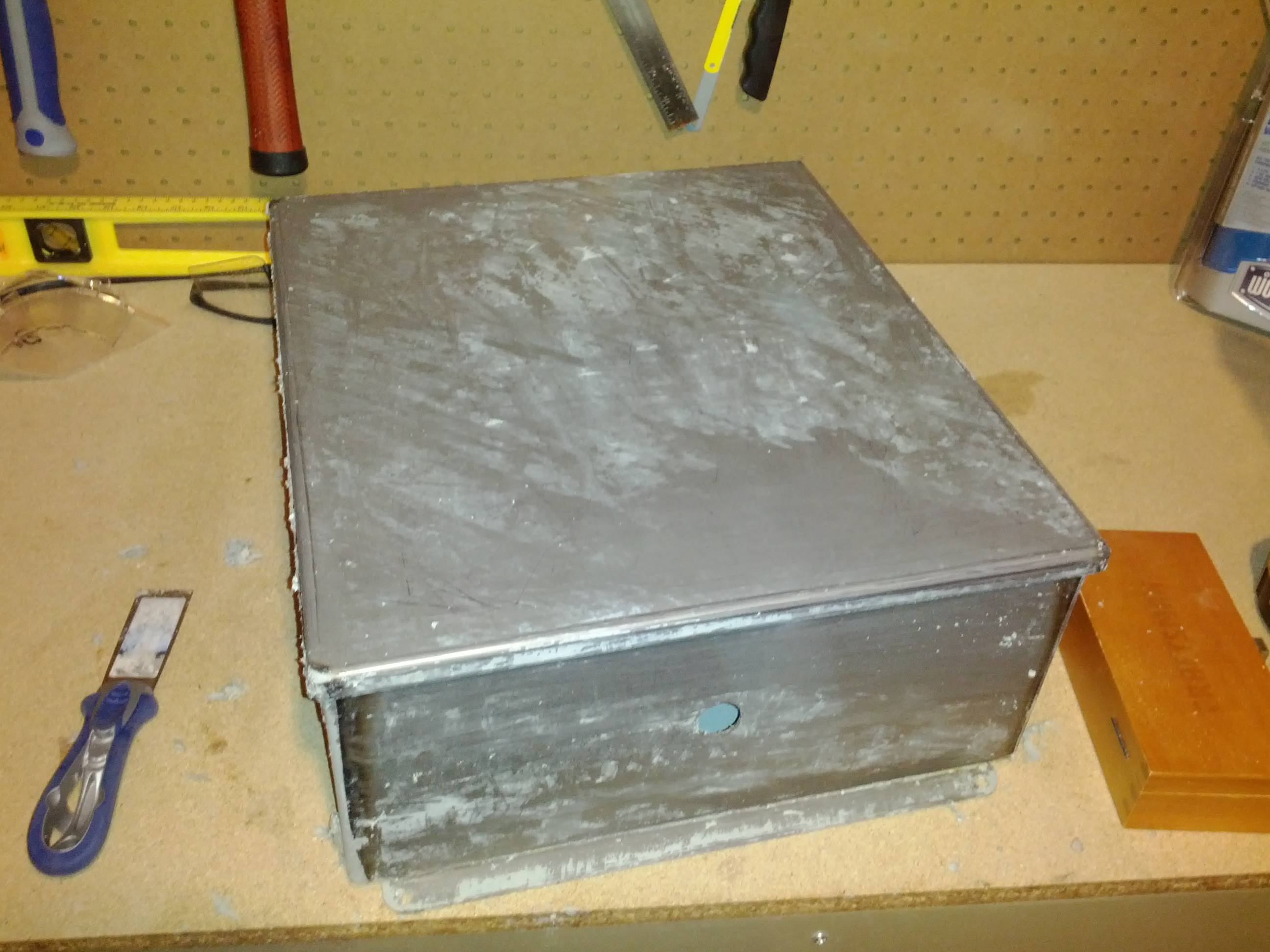
Speaking of control boxes, mine came in that wonderful SeaFoam green color that I promised would never be in my home (anyone who has been on a submarine can attest to the hatred). So I gave it the Bobby_M treatment.

(in process)


After the Bobby_M treatment:


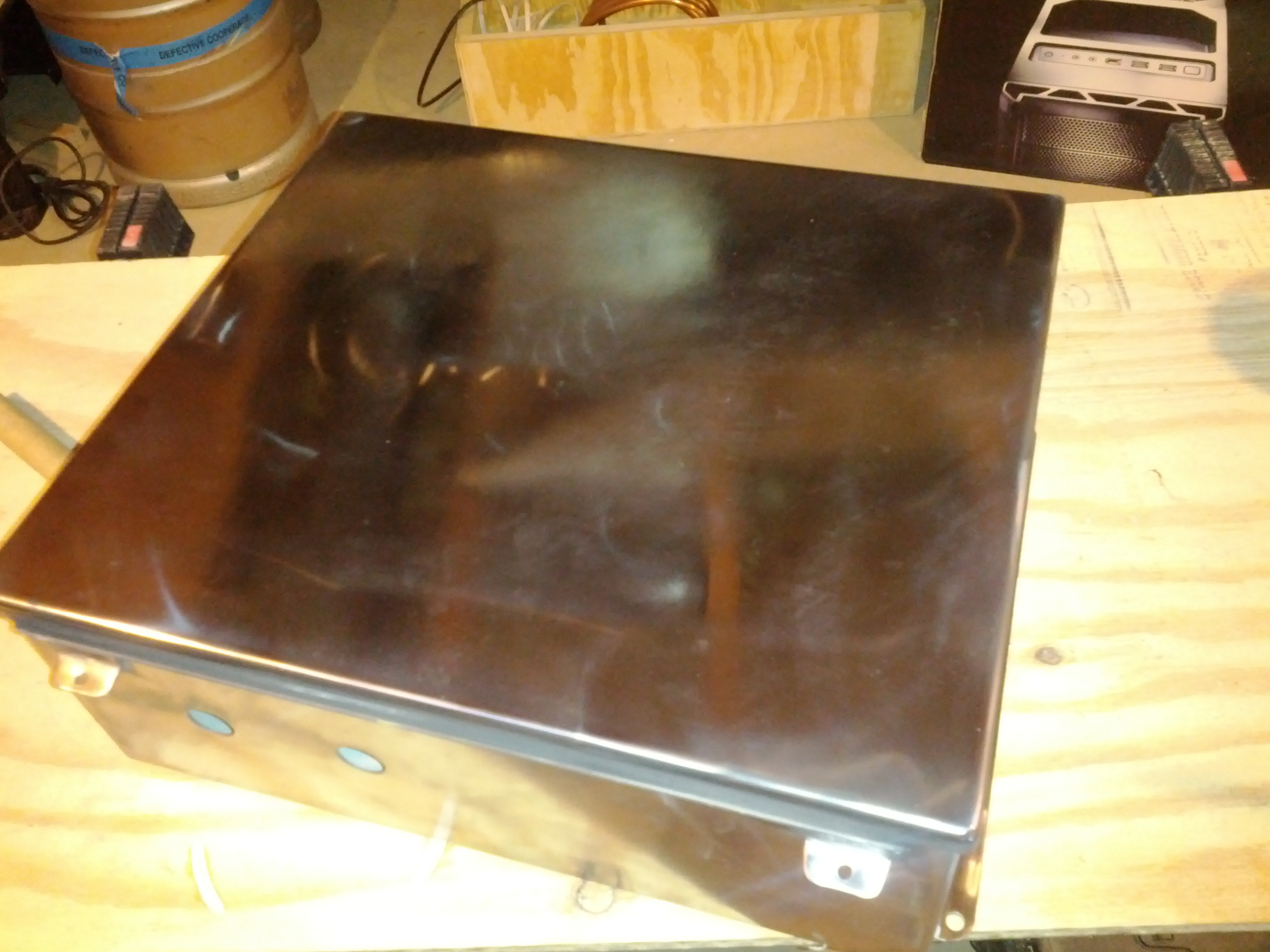
I still have holes to cut so it will get another polishing at the end.

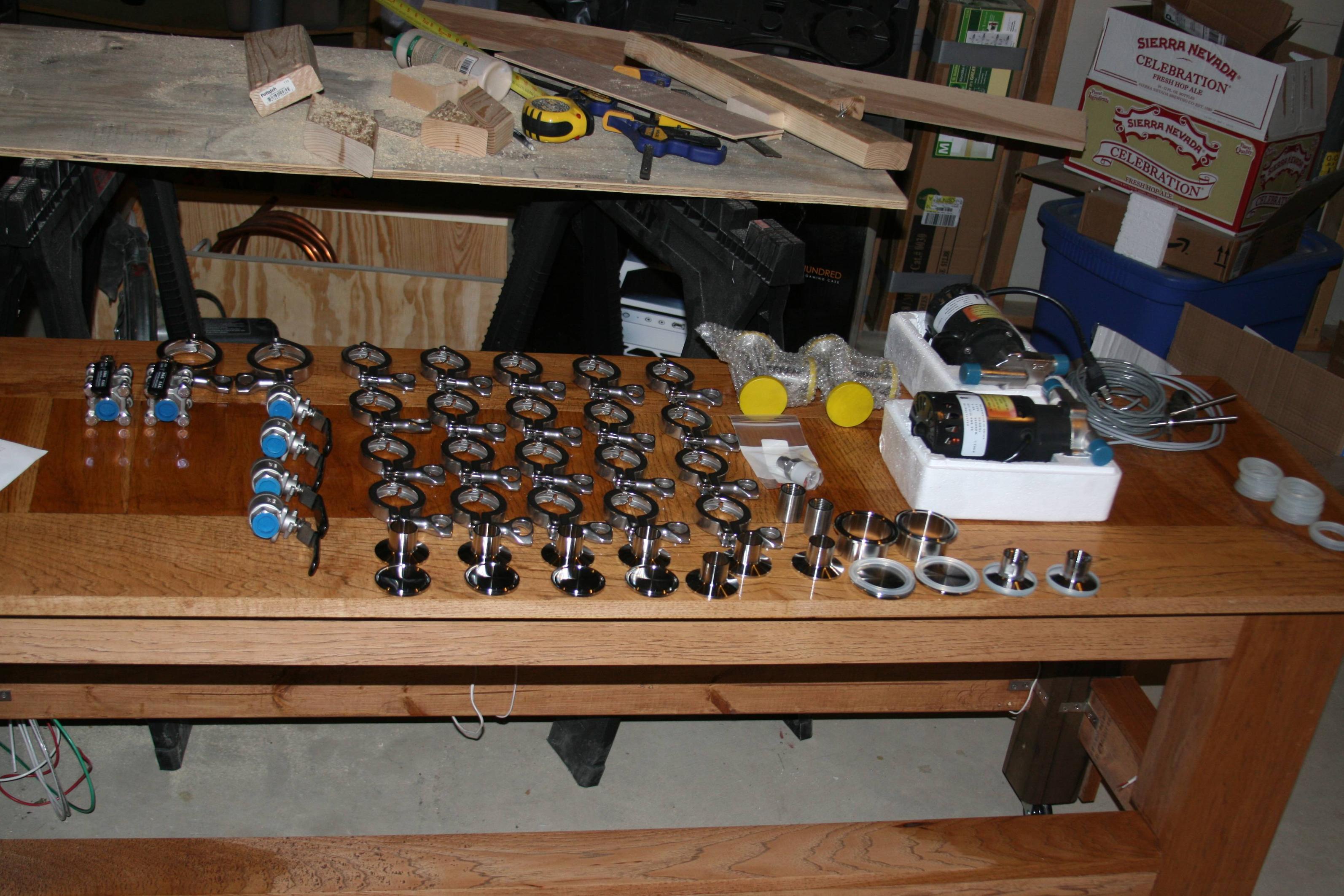
I will post more pictures as the build continues.
 
Man, it's like I'm stalking you. I'm subscribing to this thread too. I'm definitely going in the same direction you are.

Cool. I have learned a ton already from silly mistakes. Today I had to redo my wiring inside the box because I cut the hole for the receptacle that controls the pumps perpendicular to the false backing instead of parallel. Silly mistake, but I will be able to overcome, I think.

How far have you gotten along with yours?
 
Small Update:

Piping/tubing run designs are complete.


The chiller part looks complicated with too many valves because I wanted to be able to do reverse flow cleaning and this was the easiest way to do that while still maintaining SS tubing all the way through. (no silicone tube connectors)


I am trying to decide on a false bottom on the boil kettle with a bottom drain pipe or no false bottom with a side pickup. There seems to be no consensus on which way is better or at least preferred. Any ideas?:confused:
 
Backboard complete.


Now to get the other components wired and connected. Still waiting on my control switches that are apparently riding a slow boat from China.
 
Looking really nice. I'm also trapped somewhere in between the design and construction of a BCS-460 controlled one-tier, 2 pump, 2X5500W E-brewery. I've completed my control panel and finished drilling holes for heating elements (greenlee punch), and the various ins/outs/probes (Harbor freight 7/8" stepbit). Still saving dough for the BCS, probes, pumps and a brewstand.

A couple of ideas to consider. (1) What about a diverter or manifold panel? Search HBT for Wayne1, he has a couple of threads documenting a really nice approach that replicates how a brewery would move fluids. Seems unique as far as homebrewers go, but makes complete sense giving how we do things in industry. (2) False Bottoms: I'm prepared to try out a side-arm whirlpool with side pick-up. Again, Wayne1 has a nice design for this that allows you to whirlpool to centralize your trub cone, and then you transfer with a side pickup. Seems worth trying since you already need an inlet/outlet. I'm actually not sure how well a false bottom works with trub - not really like grain. I think this is why the whirlpool approach is largely favored by the big guys.

Really curious about your automated ball-valves. I love the idea, but since they look to be all-or-nothing, I'd be concerned that you won't be able to "automatically" set the proper recirc rate during mashing, and you'll get stuck mashes. Curious to hear your thoughts on this. The software side of automation is actually the easy part. Marrying it to the right plumbing and hardware seems to be the real challenge.

Good luck! :rockin:
Pete
 
So far I have run my BK with a false bottom center pick up, and no false bottom with a side pick up and a whirlpool. I could never get the false bottom center pick up to work well, I always ended up clogging the pickup tube. As for the side pick up with whirlpool I had trouble with a long pickup and getting a good cone. I have settled on using a 90º 1/2 NPT X Barb connector. where the barb is about 1/2 from the floor of the kettle. Keep in mind I am using an 75QT stock pot and NOT a keggle, and I have not installed my electric element in my system yet, I have been brewing Hybrid with Electric HLT/HERMS Mash with Propane boil, so Im not to sure how the element will effect the trub cone formation.

As for your systems drawing, how do you plan on installing the element in the HLT? Are you planing on putting above your HEX coils?

Also, If you have not cut your control box or bought all the saws and what not for cutting it your self, look in to a water jet facility to cut your control box. They can cut a control box really precise and for about the cost of all the bits and saws necessary for cutting your control pannel.
 
I'm keeping my eye on this project. It is EXACTLY what I have been wanting to build, but I do not have anywhere near the technical skills to design it. I love the idea of using the BCS as the control panel. Keep the updates coming.

I really don't understand the wiring diagram at this point, but it looks like you have just one 30A breaker, so does this mean you are only able to use 1 element at a time? It seems that running both elements at once would be great for doing double batches or starting to heat water for cleaning. I have read that 50A parts are more pricey, but is there a reason not to run two 30A 240V plugs to the brewing area?
 
TL;DR: Pretty pics! Read for my design notes.

Sorry for taking so long to respond. Life has gotten in the way a little bit, but there is some progress, mostly in getting the door wired up and trying to engineer a way to get the control box mounted on the stand. (Lesson learned: Don't build furniture then put a brewery on it, not the best idea)

Plove, you have some of my concerns nailed down, but I think that I have some solutions. Maybe not good ones, but solutions. Regarding the ball valves: yes they are not throttle valves, however I do plan on having ball valves at each tank connection that are manual ball valves, so I should be able to set the flow rates for the mash at the outlet of the HERMS coil. The whirlpool connection is also going to have a manual ball valve in line with it (mostly to help with cleaning) but it will have the ability to throttle if my mash out flow gets too high.

Here is where I think this gets slightly interesting. On the HLT, I plan on having a three way connection that has one manual ball valve, one motor operated valve, and the pump outlet going into it. The manual ball valve will be open at all times allowing the HLT to recirc on itself (and keep the HERMS coil at a more consistent temp). When the BCS demands the motor operated valve to open for fly sparging, most of the flow will still go through the manual ball valve until I start to close it, thereby controlling the sparge rate (in).

I will go look up Mr Wayne1 as well. These are just my unproven theories on how this thing is actually going to work. I originally had planned on using an air operated throttle valve as a bypass on the HERMs in case the temp got too high, but that idea was shot down by the Mrs. pretty quickly when she saw the cost.

Bsquared, I am planning on installing my heating element under the hex coils, mostly to prevent it from being dry fired. I am worried that I will not get enough flow rate out of the pump to keep the heating element from "direct" heating the HERMS coil, but it should work. By my simple calculations, I should be able to recirc the entire contents of my HLT in about 2.5 minutes. That amount of recirc should be able to keep the temperature fairly consistent throughout the HLT. As for how it is going to be connected... I'm still working on that. I plan on having it connected with 2in Triclover fitting and a drilled blank cap. How the backside is going to be connected is anyone's guess. I planned on doing the Kal method, but others on here seem to have their issues with that.

Pics!
I had to wait over a month to get my control switches from a Chinese eBay supplier. I will now buy all of my stuff from Automation Direct/ McMaster Carr. This is only about half of the total wiring that needs to be completed. :(


Micahshaw, I have a 30A breaker on the diagram at this moment, but I just picked up one of those 50A Spa Panels and will be updating the design to reflect that. It is cheaper to buy a 50A Spa Panel from HD with a GFCI breaker in it than it is to buy a 50A GFCI by itself. The major concern that I have with the 50A is that I now have to run a 50A connection into my garage and/ or basement from my main breaker panel. 6/3 wire is NOT cheap. If you have any questions on what any of the wires do, please ask. As you can see, I can make walls of text fairly easy.

Last pic of this update is my way of connecting the heavy gauge wiring.

The top two hobby boxes will have L14-30R outlets in each of them for the boil kettle element and the HLT element. The bottom hobby box has a duplex receptacle that will independently control the two pumps. It is on the backside of the stand so everything still looks nice from the front. Everything will just plug in so I can move things with ease.

May 5th looks like a pipe dream now, but I am on track.

Someone asked about cost. Nice try SWMBO. :mug:


Well over 1k at this point, and no signs of slowing down.
 
If you have any questions on what any of the wires do, please ask. As you can see, I can make walls of text fairly easy.

Well over 1k at this point, and no signs of slowing down.

I have lots of noob questions on the wiring. Fortunately I am a ways off from getting this budgeted in, so no worries about me electrocuting myself yet. Hopefully by the time I am financially ready I will also have acquired the needed technical knowledge.

It looks like the BCS isn't in your wiring diagram, and there are just 2 wire that come from the BCS to the SSRs to turn on and off the BK and HLT. Obviously there needs to be temp probs going to the BCS as well, and you have it controlling all those automated valves. I don't understand how all that is connected to the BCS. But you do have a bunch of relays and other labeled circles that must be doing these things, but I don't understand how. Also, there is a 12V DC source, which I realize must be used to run some DC parts (are the valves DC?) It is not clear to me what all the labels are. What are the BW, BW-MOV, and P labels indicating?

Sorry to be such a ignoramus about all this. If there is some place that already explains these things better, please point me to it. I am not afraid to read, but so far most of what I am reading is like your wiring diagram: vaguely logical, but just beyond my grasp of understanding.

:drunk:
 
I have lots of noob questions on the wiring.

It looks like the BCS isn't in your wiring diagram, and there are just 2 wire that come from the BCS to the SSRs to turn on and off the BK and HLT. Obviously there needs to be temp probs going to the BCS as well, and you have it controlling all those automated valves. I don't understand how all that is connected to the BCS. But you do have a bunch of relays and other labeled circles that must be doing these things, but I don't understand how. Also, there is a 12V DC source, which I realize must be used to run some DC parts (are the valves DC?) It is not clear to me what all the labels are. What are the BW, BW-MOV, and P labels indicating?

Sorry to be such a ignoramus about all this. If there is some place that already explains these things better, please point me to it. I am not afraid to read, but so far most of what I am reading is like your wiring diagram: vaguely logical, but just beyond my grasp of understanding.

:drunk:

I work at a nuclear power plant so most of the labels that I used are just simplified versions of what we have at work. I wasn't really planning on using this diagram for public consumption, but it gets the basic point across. It could definitely be labeled better.
P= pump
MOV= motor operated valve
BW= system designator (Brewing Water)

So what you are seeing there is my shorthand for what the valves are (BW-MOV-2 means brewing water motor operated valve #2) and what the pumps are (P-001 being the first of the two pumps). These names are just there to keep me from getting confused in the design process. Instead of naming the pump main recirc pump, I call it P-001 and I know which one I am talking about.

The valves that I am using are these for the motor operated valves, which are the 12V DC valves. I would have preferred 120V, but beggars can't be choosers when it comes to motor operated ball valves. I was going to go with these but solenoid operated diaphragm valves are a PITA to clean properly and have a propensity to fail in fairly creative ways. Basic ball valves with a motor operator are much better at controlling flow without having to worry about a diaphragm failure. I am probably going to use one of the diaphram valves on my water in portion of my project, but that is WAY out in the future.

I did not put any of the controls from the BCS on the wiring diagram because the connections are dirt simple from the BCS to the control box. If you zoom in on the control box picture above you will see the relay board has a big bank of connections at the bottom; that is where almost all of the BCS connections go into, via two terminal board connections. The terminal board connections have the connections for the temperature probes connected directly to them and they feed the BCS. I have an excel spreadsheet that shows what is on each terminal board and where the connections go. I would definitely suggest using a spreadsheet to keep track of all of your connections.

Also, one of the things that I did not explain very well in my initial post is that I am using two of the small SSRs as interlocks for the main 25A and 40A SSRs. The interlock serves three purposes:
1. it takes two signals from the BCS to turn on the kettles
2. I can have the Emergency stop pushbutton only block 120V to the small SSRs and turn off my 240V to my kettles
3. If I decide to put additional interlocks (level interlocks to prevent dry firing for instance) I can do it at 120V and block the signal to the SSRs or I can feed it directly into the BCS via the DIN connections on the BCS.

Flexibility is key in my design. Most of the circles that you see on the diagram are receptacles of different sizes and shapes (some big 240V female receptacles, some 120V like on your wall and some microphone connectors like these.. There are additional control switches that are labeled with (Auto-Off-On). Those are also there to just provide flexibility, mostly for cleaning.

Keep asking questions! This is kinda fun.
 
Last edited by a moderator:
I work at a nuclear power plant so most of the labels that I used are just simplified versions of what we have at work. I wasn't really planning on using this diagram for public consumption, but it gets the basic point across. It could definitely be labeled better.
P= pump
MOV= motor operated valve
BW= system designator (Brewing Water)

So what you are seeing there is my shorthand for what the valves are (BW-MOV-2 means brewing water motor operated valve #2) and what the pumps are (P-001 being the first of the two pumps). These names are just there to keep me from getting confused in the design process. Instead of naming the pump main recirc pump, I call it P-001 and I know which one I am talking about.

First off, this whole diagram is making a ton more sense now. However, this seems like it should be obvious, but I can't figure out what the BW-S-5 is controlling. I can't think of another 120V system you are using that for.

I did not put any of the controls from the BCS on the wiring diagram because the connections are dirt simple from the BCS to the control box. If you zoom in on the control box picture above you will see the relay board has a big bank of connections at the bottom; that is where almost all of the BCS connections go into, via two terminal board connections. The terminal board connections have the connections for the temperature probes connected directly to them and they feed the BCS. I have an excel spreadsheet that shows what is on each terminal board and where the connections go. I would definitely suggest using a spreadsheet to keep track of all of your connections.

Also, one of the things that I did not explain very well in my initial post is that I am using two of the small SSRs as interlocks for the main 25A and 40A SSRs. The interlock serves three purposes:
1. it takes two signals from the BCS to turn on the kettles
2. I can have the Emergency stop pushbutton only block 120V to the small SSRs and turn off my 240V to my kettles
3. If I decide to put additional interlocks (level interlocks to prevent dry firing for instance) I can do it at 120V and block the signal to the SSRs or I can feed it directly into the BCS via the DIN connections on the BCS.

Ok, a couple questions here. I am still not clear what the "Relays" are. Are these 25A SSRs? Is this what the BCS inputs are controlling? This seems to make sense, if I am interpreting the diagram correctly, but there are no heatsinks on them. Are they not needed here?

But then I look at how the 40A SSR is hooked up, and I guess I don't understand how this part works at all. It looks to me like the 40A SSR has a red 240V line (which is positive 120V?) and a blue 120V line coming in, and a BCS control line. I guess I don't understand how the SSR is suppose to be wired. To simplify it, I thought it basically had an "in", and "out", and an "on/off," but this is clearly not the case here. Also, The black 240V line (the negative 120V?) goes directly into the plug, and will always be powered even when the SSR is off. Without a complete circuit, that's fine, but is this a potential risk if water were to cause a short? Particularly since the E-Stop does nothing to kill this line?

Also, where did you get this relay board?

Flexibility is key in my design. Most of the circles that you see on the diagram are receptacles of different sizes and shapes (some big 240V female receptacles, some 120V like on your wall and some microphone connectors like these.. There are additional control switches that are labeled with (Auto-Off-On). Those are also there to just provide flexibility, mostly for cleaning.

I am still debating on weather or not to have all the on/off/auto switches. Lots of extra wiring/cost, and should not be needed with the BCS web interface. You can just turn things on and off via the web interface from a tablet. However, the physical switch is easy and pretty fail safe. Plus, you know, its just super cool to have lots of knobs, lights, and switches. :D

But for cleaning, I think it would be ideal to have a "cleaning" program that would warm up some oxyclean and start running it through the whole system. (Maybe this level of simplicity in cleaning is a pipe dream, particularly without adding additional input to monitor fluid levels, but I am not a big fan of doing the dishes)

Keep asking questions! This is kinda fun.

Hope I haven't made you regret this remark. I am learning a lot! :mug:

micah
 
Last edited by a moderator:
I'm in the process of running the line between my main box and spa panel. I had an electrcian review my plans, he recommended 8/3 not 6/3 for the wire. My plan was also to possibly run an arc welder off the same circuit in the future.
 
First off, this whole diagram is making a ton more sense now. However, this seems like it should be obvious, but I can't figure out what the BW-S-5 is controlling. I can't think of another 120V system you are using that for.

BW-S-5 (solenoid valve is what the S stands for) is that valve I was talking about earlier for future expansion. I plan on having it be a water in valve that will do the initial fill of the HLT and will provide cooling water to the wort chiller. As of today, all of the wiring will be set up for that part of the project, but I am just going to have a manual valve controlling all of the water in until I am ready for that part of the project.


Ok, a couple questions here. I am still not clear what the "Relays" are. Are these 25A SSRs? Is this what the BCS inputs are controlling? This seems to make sense, if I am interpreting the diagram correctly, but there are no heatsinks on them. Are they not needed here?

The relays are small project relays found here. They are basically computer controlled on-off switches. They do not do any heavy lifting (no major loads, not cycling on and off multiple times a second) so they do not need heat sinks. The reason that the 25 and 40A SSRs need heat sinks is because they are doing the heavy lifting of boiling with high currents and cycling multiple times a second. The BCS puts out a simple 5V signal that is either 5V or 0V (on or off). The relay(s) have either 12V or 120V on the goes in and what the relay is controlling on the goes out connection. When the BCS demands the valve open, it sends a 5V signal down its associated line to the relay, the relay changes state and allow current flow to open the valve. (If this is too basic, I'm sorry for explaining it, just want to make sure that we are on the same page)

But then I look at how the 40A SSR is hooked up, and I guess I don't understand how this part works at all. It looks to me like the 40A SSR has a red 240V line (which is positive 120V?) and a blue 120V line coming in, and a BCS control line. I guess I don't understand how the SSR is suppose to be wired. To simplify it, I thought it basically had an "in", and "out", and an "on/off," but this is clearly not the case here. Also, The black 240V line (the negative 120V?) goes directly into the plug, and will always be powered even when the SSR is off. Without a complete circuit, that's fine, but is this a potential risk if water were to cause a short? Particularly since the E-Stop does nothing to kill this line?

Ok, 240v is essentially two 120V connections, one red wire and one black wire inside your breaker box that is touching two different bus bars that are 180 degrees out of phase from each other (not important for this part of the lecture, don't dwell on that). The red line is not controlled by the BCS, you are correct and it doesn't truly need to be. Some people do put an SSR on both leads, I feel that it is unnecessary. I believe that Ohio-Ed did it this way. So one line is providing 120v at its peak and the other is providing 120V at its opposite polarity valley, thereby giving you 240v across the two. If one interrupts the voltage on one side of that circuit, no current will flow. That is how you can get away with using just one SSR. To read more, the wiki is a good read.

Here is a stick figure diagram of how the BCS control signal is wired to the "big" SSRs.

BCS Dout -------- Small SSR for interlock ------ Big SSR in/out----- BCS GND
Dout=digital out

I hope the description above helps you see why the E-stop will work for blocking power. There may be some bleed through current, but I am not worried about bleed through current on an emergency stop. I am worried about big ass fires. Killing 40A and having maybe 10 milliamps flowing I can take.

Also, where did you get this relay board?
Ebay. See link above


I am still debating on weather or not to have all the on/off/auto switches. Lots of extra wiring/cost, and should not be needed with the BCS web interface. You can just turn things on and off via the web interface from a tablet. However, the physical switch is easy and pretty fail safe. Plus, you know, its just super cool to have lots of knobs, lights, and switches. :D

But for cleaning, I think it would be ideal to have a "cleaning" program that would warm up some oxyclean and start running it through the whole system. (Maybe this level of simplicity in cleaning is a pipe dream, particularly without adding additional input to monitor fluid levels, but I am not a big fan of doing the dishes)


Hope I haven't made you regret this remark. I am learning a lot! :mug:

micah

The switches, if bought on Ebay from Chinese suppliers (see story above about this), will only add about 3$ per switch. Mine cost 19$ shipped for all 6. It just took forever to get here. The wire you are already going to have anyway so that is truly a sunk cost. If you use automation direct, the switches are about 15$ for the LED illuminated ones. The decision is completely up to you. The truth about my design is that my rig was going to be a gas fired basic system with no computer control which is why I had all of the switches already in place. When I found the BCS, I kinda just made it work into the design. To me, that is why there is so much extra stuff in my control box. Some people can get away with mounting their BCS in their control box, putting a few relays in there and closing the door. Mine is a little more complicated, but I like it. There are not many like it, but this one is mine. :)

I do have a cleaning mode on my BCS that runs in a separate tree, but I wanted the ability to turn the pumps on and off at a switch so when I reverse flow through the wort chiller, I can turn the pump off to prevent dead heading the pump. I am kinda old school that way.

Keep bringing it mate!

tator2k, thanks for the tip. I will look again. I may have been looking at using aluminum wiring, which if memory serves would need the larger gauge. I will look at the cost of the copper. I am certain it is still an arm and a testicle though. At least I have two of both!:mug:
 
The BCS puts out a simple 5V signal that is either 5V or 0V (on or off). The relay(s) have either 12V or 120V on the goes in and what the relay is controlling on the goes out connection. When the BCS demands the valve open, it sends a 5V signal down its associated line to the relay, the relay changes state and allow current flow to open the valve. (If this is too basic, I'm sorry for explaining it, just want to make sure that we are on the same page)

This makes perfect sense.

Ok, 240v is essentially two 120V connections, one red wire and one black wire inside your breaker box that is touching two different bus bars that are 180 degrees out of phase from each other (not important for this part of the lecture, don't dwell on that). The red line is not controlled by the BCS, you are correct and it doesn't truly need to be. Some people do put an SSR on both leads, I feel that it is unnecessary. I believe that Ohio-Ed did it this way. So one line is providing 120v at its peak and the other is providing 120V at its opposite polarity valley, thereby giving you 240v across the two. If one interrupts the voltage on one side of that circuit, no current will flow. That is how you can get away with using just one SSR. To read more, the wiki is a good read.

This all makes perfect sense. The 180 degrees out of phase is what I meant by Positive and Negative 120V. Its been awhile since I took a circuits class.

Here is a stick figure diagram of how the BCS control signal is wired to the "big" SSRs.

BCS Dout -------- Small SSR for interlock ------ Big SSR in/out----- BCS GND
Dout=digital out

I hope the description above helps you see why the E-stop will work for blocking power. There may be some bleed through current, but I am not worried about bleed through current on an emergency stop. I am worried about big ass fires. Killing 40A and having maybe 10 milliamps flowing I can take.

And here is where I loose you. I looked up some info on wiring an SSR, and I attached a quick diagram of how I IMAGINE this should be hooked up, but it appears to be different than what you have diagrammed. First, you are using a 120V control to the SSR, which seems reasonable, if thats how the SSRs you have work, but I thought they needed a DC control signal (and I seem to recall it being said that 12V is a more appropriate control signal). But more important, your diagram seems to have the red leg of the 240V being switched, and you have a 120V input coming through the BCS controlled relay, AND another BCS control line. Whats the deal here? Is this just going to BCS ground? I have been assuming that the BCS ground would be tied into a common ground and shared across all those relays, as well as being the ground on the 120V plugs. Also, you keep talking about a 25A SSR, which I do not see in your diagram.

Assuming it is the 120V line coming through the relay that is controlling the 40A SSR, then I see how the E-Stop will cause this to turn off (tho I guess the E-Stop is really not design to protect against electrocution, that's what the GFI is for)


The switches, if bought on Ebay from Chinese suppliers (see story above about this), will only add about 3$ per switch. Mine cost 19$ shipped for all 6. It just took forever to get here. The wire you are already going to have anyway so that is truly a sunk cost. If you use automation direct, the switches are about 15$ for the LED illuminated ones. The decision is completely up to you. The truth about my design is that my rig was going to be a gas fired basic system with no computer control which is why I had all of the switches already in place. When I found the BCS, I kinda just made it work into the design. To me, that is why there is so much extra stuff in my control box. Some people can get away with mounting their BCS in their control box, putting a few relays in there and closing the door. Mine is a little more complicated, but I like it. There are not many like it, but this one is mine. :)

I do have a cleaning mode on my BCS that runs in a separate tree, but I wanted the ability to turn the pumps on and off at a switch so when I reverse flow through the wort chiller, I can turn the pump off to prevent dead heading the pump. I am kinda old school that way.

Alright, you have me convinced. I do love the idea of having all the switches and what-not available.

Keep bringing it mate!

I'm gonna wear you out. ;)

Micah

SSR Hookup.JPG
 
This makes perfect sense.

And here is where I loose you. I looked up some info on wiring an SSR, and I attached a quick diagram of how I IMAGINE this should be hooked up, but it appears to be different than what you have diagrammed. First, you are using a 120V control to the SSR, which seems reasonable, if thats how the SSRs you have work, but I thought they needed a DC control signal (and I seem to recall it being said that 12V is a more appropriate control signal). But more important, your diagram seems to have the red leg of the 240V being switched, and you have a 120V input coming through the BCS controlled relay, AND another BCS control line. Whats the deal here? Is this just going to BCS ground? I have been assuming that the BCS ground would be tied into a common ground and shared across all those relays, as well as being the ground on the 120V plugs. Also, you keep talking about a 25A SSR, which I do not see in your diagram.

Assuming it is the 120V line coming through the relay that is controlling the 40A SSR, then I see how the E-Stop will cause this to turn off (tho I guess the E-Stop is really not design to protect against electrocution, that's what the GFI is for)

I'm gonna wear you out. ;)

Micah

Here is my poorly drawn and crummy handwriting showing you how the interlock is set up. I colorized it in MS paint. That is how hard I am.

Dout1 is the PID controlled line that runs to the big relays via the small guy, Dout2 is a simple on/off line that is exclusively for the interlock.

I see what you are saying now and I may have to go back to the drawing board. The interlocks were put into place where I would have to have two signals from the BCS to get signal power to the Big SSRs. (BTW, I have a 40A SSR for the boil kettle that is covering a 5500W element and a 25A SSR that is covering a 3500W element. They sent me the wrong SSR and I just decided to use it instead of dealing with the hassle of returns and whatnot). I don't have a copy of Visio here to give you a better diagram of this, but I can make one up at work tomorrow. Unless crappily drawn hand drawings work...

Here is where you are right and I missed the problem. I don't have anything that will kill the 240V power going to the big SSRs. I think I need to get a mechanical relay into the mix. Back to the drawing board! Great catch. That is why I put it up here before testing it. I think a simple DPDT relay would work because I could just run the two PID controlled BCS lines through the relay and have 120V as the control circuit. E-stop actuates, the 120v is cut out, relay opens, opens the PID control circuits, kettles go off. That would work. Now... where to put a cube relay in this crammed box.:drunk:

Regarding the BCS ground, I am using it for all of the 5v returns. If the case ground has to be used for any reason, there will be a TON of current that will hit that thing. I would rather waste the money on having all of the signals return to the BCS than have a BCS paperweight in the event of a malfunction.

Thanks again for finding the design flaw.
 
Here is my poorly drawn and crummy handwriting showing you how the interlock is set up.

Dout1 is the PID controlled line that runs to the big relays via the small guy, Dout2 is a simple on/off line that is exclusively for the interlock.

I see what you are saying now and I may have to go back to the drawing board. The interlocks were put into place where I would have to have two signals from the BCS to get signal power to the Big SSRs.

Alright, this diagram is definitely different that what you originally posted. The unlabeled interlock is equivalent to relays 3 and 4 from your original diagram? In the original diagram the relay is controlling a 120V power line which then connects in some way that I don't understand to the SSR. Then there is a second signal from the BCS. Which one of these is suppose to actually control the SSR?

In this new diagram, you have a relay controlled by the BCS switching the Dout1, also controlled by the BCS. What is the advantage here? Do you feel like somehow the Dout1 might get turned on accedentally? And if so, what makes you believe that both control signals won't be turned on accedentally?

I don't have a copy of Visio here to give you a better diagram of this, but I can make one up at work tomorrow. Unless crappily drawn hand drawings work...

I think I understand the drawing.

Here is where you are right and I missed the problem. I don't have anything that will kill the 240V power going to the big SSRs. I think I need to get a mechanical relay into the mix. Back to the drawing board! Great catch. That is why I put it up here before testing it. I think a simple DPDT relay would work because I could just run the two PID controlled BCS lines through the relay and have 120V as the control circuit. E-stop actuates, the 120v is cut out, relay opens, opens the PID control circuits, kettles go off. That would work. Now... where to put a cube relay in this crammed box.:drunk:

I guess I don't see a reason not to put the Double Pole Contactor between the 240V source and the distribution block. Add a master power switch in front of the E-Stop (just for ease of being able to ensure the thing is turned off), and run a control line from the 120V to the Contactor. Then if power is off, or the E-Stop is hit, there is a physical disconnect from both poles of the 240V elements. No bleed through, no 120V differential sitting at one of the poles of the element. This means if a buddy is helping out and grabs the HTL while the black pole of the 240V is somehow shorted to the kettle, the E-Stop will kill that power as well. That being said, I think I just read in another thread that there might be a reason to put the contactor AFTER the SSR. I am not sure why, and it would mean finding space (and money) for 2 contactors instead of one, but I thought I would just mention that.

I am also still confused about the use of the 120V control line. Is your SSR controlled by a 120V AC control line? I though it was controlled via a 12V DC control line. I would think that you should have relays 3 and 4 switching a 12V DC signal instead of a 120V AC signal, and then drop the BCS connection to the SSR completely, as I don't know what its actually doing there.

Regarding the BCS ground, I am using it for all of the 5v returns. If the case ground has to be used for any reason, there will be a TON of current that will hit that thing. I would rather waste the money on having all of the signals return to the BCS than have a BCS paperweight in the event of a malfunction.

Thanks again for finding the design flaw.

That sounds like a reasonable idea for ground connections, I agree with not wanting the BCS to get fried!

I have been reading a lot of E-build design threads trying to get me head around all of the concepts being used. Really thinking through your design and trying to make sure I completely understand every aspect has been a HUGE help in figuring out exactly what I don't know, and what I need to look into more. I do appreciate the responses, and I am glad it has also been at least somewhat helpful for you as well.

BTW: I a really looking forward to you finishing up the wiring and getting some pics of it.

Micah
 
My packages from Brewer's Hardware showed up today.

iZvpy.jpg


That is a ton of stainless. This is going to be an adventure. I definitely need more triclover caps to make fittings.
 
Holy tri-clovers is right!

Interested to see how you like them during brewday. You probably mentioned this, but is this going to be a hard-lined system from the get-go? I decided to go with Camlock fittings over sanitary tri with the idea that I'll eventually build a diverter panel for switch and play like the big breweries.

Following your progress with great interest. My BCS360 is in the mail and I'm hoping to tie it to a bridger router this weekend.

PLOVE
 
Denny330 said:
My packages from Brewer's Hardware showed up today.

That is a ton of stainless. This is going to be an adventure. I definitely need more triclover caps to make fittings.

Not too shabby. Shame I can't take pics at work. Y'all would soil yourselves with all the tri-clamp fittings. Side effect of a plant that handles a couple million pounds of milk daily - lots of equipment porn.

If you've got really obscene amounts of money to throw around, then flowverter panels are passe. We're using sanitary cross-body mixproof valves now. They're about $4k each, plus the programming to drive them, but when you've got a process that requires swinging 50+ jumpers to go from production to sanitation, the payoff in time and ergonomics meant the capital paid for itself in a year or so.
 
Holy tri-clovers is right!

Interested to see how you like them during brewday. You probably mentioned this, but is this going to be a hard-lined system from the get-go? I decided to go with Camlock fittings over sanitary tri with the idea that I'll eventually build a diverter panel for switch and play like the big breweries.


PLOVE

I am doing all hard piping. I am trying to decide (quickly) if I want to stay with 1/2 in or go full 1in tubing. There is very little cost difference between the two and I cannot see going through all of this expense just to bottleneck the piping. All of the valves I have right now are 1/2 in, but I think I can deal with that. It is going to be ten tons of hell getting that last piece aligned perfectly, but I am going to try!

I half regret going hard piping now, but I figured that I would eventually want to go full hard piping, so I just decided to jump in with both feet. It has made this project a royal PITA, but I will survive. Sizing issues, triclover gasket issues, not finding anything at all in the .75 triclover size... it is all just a pain.

bdjohns1, glad to see another Wisconsinite in my thread. I am a bit north of you. I work in a nuclear power plant so there is all sorts of stainless porn at my work, but most of it would be just silly to post. I would be interested in some of the craziness that you deal with on a daily basis.
 
Back
Top