eBIAB PID Controller Wiring Diagram - Feedback Requested

Homebrew Talk - Beer, Wine, Mead, & Cider Brewing Discussion Forum

Help Support Homebrew Talk - Beer, Wine, Mead, & Cider Brewing Discussion Forum:

This site may earn a commission from merchant affiliate links, including eBay, Amazon, and others.
Joined
Sep 4, 2011
Messages
18
Reaction score
0
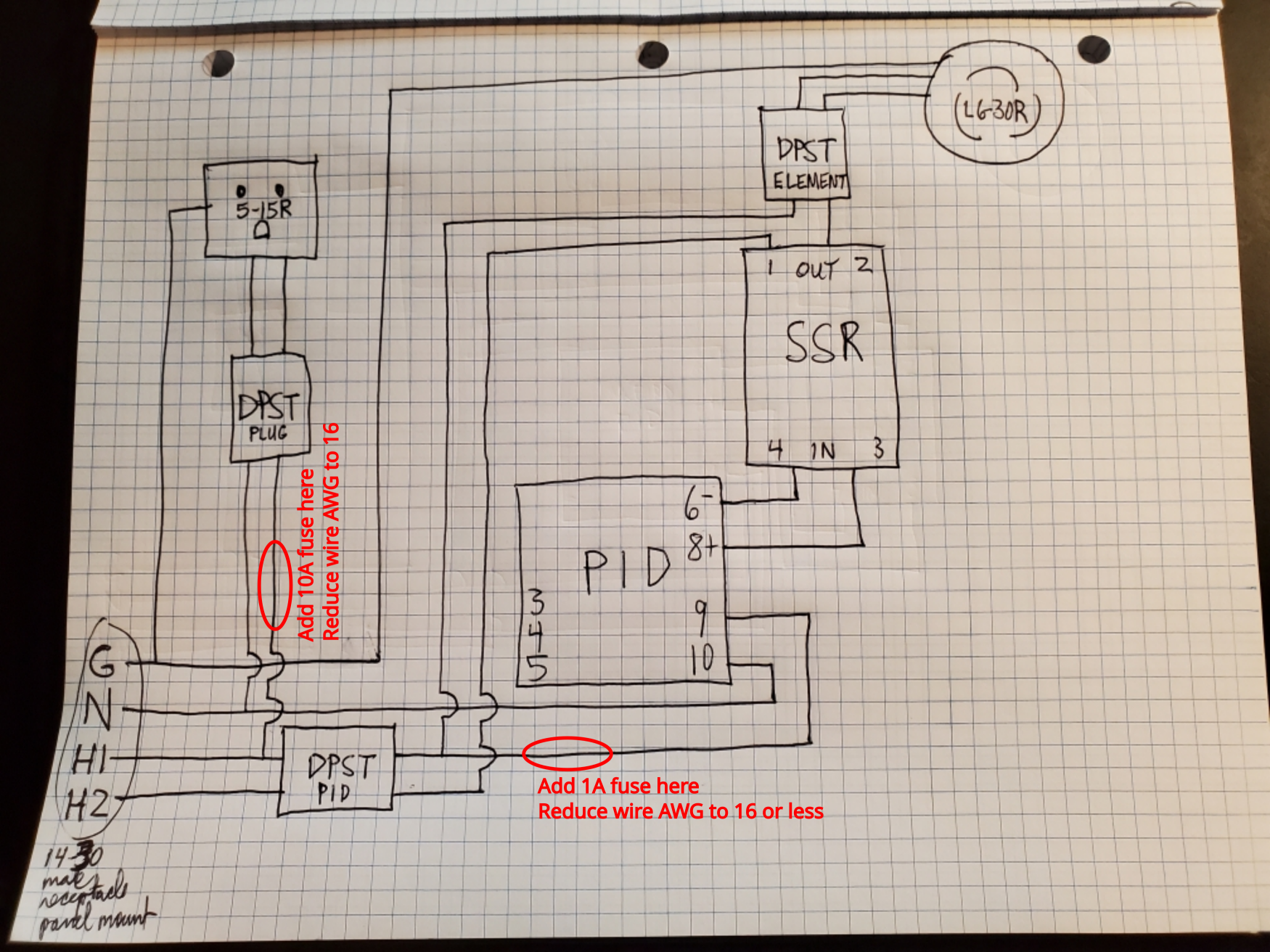
I'm looking for help with my wiring diagram for a controller. First off, some constraints. I have a 240V 14-50R outlet (4 wires) with a 50 amp GFCI breaker in the panel and an Inkbird PID controller. (I know, should've bought a PID that was built for brewing.) Due to the outlet and my desire to preserve the ability to drop a 120V plug in this or a future controller, I'm using a 14-50P to 14-30R adapter, then a 14-30P to 14-30R cord that'll go to the controller. The controller will have a panel mount L14-30R (male) receptacle so I don't have wires hanging out of the box. I'll be powering a 5500 W heating element (drawing 23 amps at 240V), so 10 AWG wire is used for 240V connections inside the box. In my schematic, I have 3 red rocker DPST switches for (1) the PID controller, (2) the L6-30R outlet to the heating element, and (3) the 5-15R outlet. I'm grounding outlets to the incoming ground wire. I've got a 60 amp SSR with heat sink. I don't think I'll have room for my 50 mm 5VDC fan and its power supply. At this point, I haven't added a 30 amp GFCI breaker or fuse(s). I'm not sure they're needed given I have the 50 amp breaker, though I think I won't be protected between 30 and 50 amps. If I installed a fuse, I'm not sure where it'd/they'd go. Would I need two 30 amp fuses, one at each hot wire entry to the box? Anyway, I'll stop here. Please take a look at the diagram. My box is roughly 4x6x8, which leave precious little room due to the two giant flush mounted receptacles. Thanks for taking a look.
 

Attachments

  • PID Controller Wiring Diagram.jpg
    PID Controller Wiring Diagram.jpg
    6.4 MB · Views: 0
Same question as Bobby about the switches. What are the switch manufacturer and PN?

You have to put in 30A overcurrent protection (fuses or breaker) before you drop down to 10AWG wire. Both hot wires have to be protected, so you need two fuses, or a double pole breaker.

If you can't fit everything in the box you have chosen, you need to bite the bullet and get a bigger box.

Brew on :mug:
 
.Same question as Bobby about the switches. What are the switch manufacturer and PN?

You have to put in 30A overcurrent protection (fuses or breaker) before you drop down to 10AWG wire. Both hot wires have to be protected, so you need two fuses, or a double pole breaker.

If you can't fit everything in the box you have chosen, you need to bite the bullet and get a bigger box.

Brew on :mug:
Makes sense, thanks. Here is the switch manufacturer/info. DaierTek 30A 250V KCD2 KCD4 Rocker Switch DPST 4 Pin Red Lighted 120V Rocker Toggle Switch ON Off Heavy Duty T125-3Pack
 
Unless you want to use 10AWG wire for everything in your control box (a bad idea) you will need to add fuses where you reduce wire size. You only have to fuse hots, not neutral. Below are my recommendations:

BIAB controller feedback.png


Brew on :mug:
 
It was very kind of you to take the time to edit my diagram and share your knowledge with me. Thank you.
 
Personal preference, but I don't see a need for the DPST "PID" switch to also carry the full 24amp load. If the whole point is to turn the PID electronics off, you can just switch the line that goes to PID pin 9. You already have the element enable switch doing the heavy lifting.
 
Personal preference, but I don't see a need for the DPST "PID" switch to also carry the full 24amp load. If the whole point is to turn the PID electronics off, you can just switch the line that goes to PID pin 9. You already have the element enable switch doing the heavy lifting.
Yes, that makes better sense. Less load on the switch (and less to hook up to the switch too). Thanks!
 
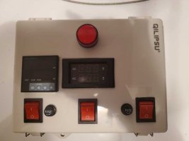
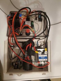
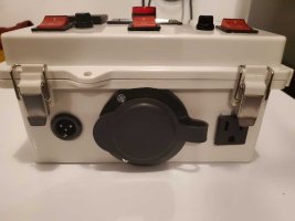
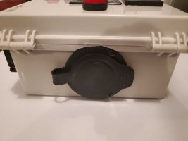
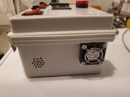
Finished the controller. I barely managed to make everything fit. The illuminated DPST switches don't light up with only 120V passing through just one pole. Also, the indicator light turns on when the element switch is turned on even when the element is not plugged in and drawing power. I think it may be leakage from the switch or lack of insulation on the small gauge wires between switch and indicator light. Other than that, it appears to work as intended, although I haven't yet tested it with the element. Here are the pictures. Oh, I haven't labeled the switches, but left to right it's PID/fan, element (ready to engage), and plug (for pump). I like that no wires stick out.
 

Attachments

  • top.jpg
    top.jpg
    57 KB · Views: 0
  • inside.jpg
    inside.jpg
    123.5 KB · Views: 0
  • front.jpg
    front.jpg
    63.8 KB · Views: 0
  • back.jpg
    back.jpg
    52.9 KB · Views: 0
  • right side.jpg
    right side.jpg
    71 KB · Views: 0
An element lamp/indicator is not a power indicator, not in regard that it depends on the element to draw power to make it light up.

If there is voltage present the lamp will light up regardless if element is connected or not.

SSRs typically have some "leakage" that will show up as passing voltage (but not allowing much current) with no load connected. Could be enough to light a small lamp/LED. It'll probably go out when the element is connected. But, it's sorta a guess since I don't see on the drawing how the element indicator is wired up and not really seeing it based on the drawing. If it's wired on the "hot" side it may just be getting voltage from line.

Also, are those automotive low voltage fuses/fuse holders?
 
Last edited:
I barely managed to make everything fit. The illuminated DPST switches don't light up with only 120V passing through just one pole. Also, the indicator light turns on when the element switch is turned on even when the element is not plugged in and drawing power. I think it may be leakage from the switch or lack of insulation on the small gauge wires between switch and indicator light.
These switches need either hot1 and hot2 switched, or one hot and neutral switched in order to light up. Do your 120V switches switch neutral as well as a hot?
An element lamp/indicator is not a power indicator, not in regard that it depends on the element to draw power to make it light up.

If there is voltage present the lamp will light up regardless if element is connected or not.

SSRs typically have some "leakage" that will show up as passing voltage (but not allowing much current) with no load connected. Could be enough to light a small lamp/LED. It'll probably go out when the element is connected. But, it's sorta a guess since I don't see on the drawing how the element indicator is wired up and not really seeing it based on the drawing. If it's wired on the "hot" side it may just be getting voltage from line.
This is exactly what happens. SSRs are not perfect switches, as they leak a small amount of current when off. It's only a few mA of current, but enough to light up an LED indicator if there is not a load in parallel with the indicator. It will work as expected when the element is connected.

Brew on :mug:
 
Keep an eye on the SSR temperature. I like externally mounted heatsinks but if you must keep it inside, more holes for intake may be necessary.
Good point. I should have looked at the pics. I don't see what I would consider enough air exhaust holes.

Brew on :mug:
 
Finished the controller. I barely managed to make everything fit. The illuminated DPST switches don't light up with only 120V passing through just one pole. Also, the indicator light turns on when the element switch is turned on even when the element is not plugged in and drawing power. I think it may be leakage from the switch or lack of insulation on the small gauge wires between switch and indicator light. Other than that, it appears to work as intended, although I haven't yet tested it with the element. Here are the pictures. Oh, I haven't labeled the switches, but left to right it's PID/fan, element (ready to engage), and plug (for pump). I like that no wires stick out.
Last weekend, I used the controller to brew. It worked well. No issues. I equipped a steam slayer, which requires one to control the percentage output to the heating element. The Inkbird 106VH does have that feature, but it's buried in the menus a bit. You have to switch from PID to manual mode. The menu isn't intuitive, but you can do it. Also, the rate of water loss on the 6 GPH Steam Slayer was basically the same (0.7 gallons per hour at 33-34% output) as what brewhardware.com says it would be with condensate coming out a bit below 140 F. This was most pleasing/reassuring.
 
Back
Top