Ok I'm sure this has probably been asked a few times in this thread but, I can't read 1,000 + posts ...... believe me though I did try. My question is this on page one I fully understand the wiring diagram as I do have a rudimentary education in electrical wiring. I also do notice in that first diagram a few things missing such as switches ( optional ) and indicator lights. I'm pretty sure I understand how to wire in the inicators etc..... My real question is in a lot and I mean a lot of other RIMS posts online not necessarily on HBT I see people putting in extention bars for more terminals as well as dramatically different wiring and control selections. I understand there are many ways to skin a cat ( no offense to PETA ) but, is the OP's diagram only meant for a bare bones simple no frills RIMS or is there any other sources that fully show a schematic with those bells and whistles like indicator lights , manual overrides, safety fuses etc..... ? I want to use the OP's schematic as a jump off point but incorporate fuse protection for the element as well as including indicator light and isolation switches so I can run the pump alone to recirculate and "vorlauf" and then turn on the element and control to step and maintain the mash temps. THanks for any input.
You are using an out of date browser. It may not display this or other websites correctly.
You should upgrade or use an alternative browser.
You should upgrade or use an alternative browser.
RIMS for Dummies
- Thread starter Sawdustguy
- Start date

Help Support Homebrew Talk - Beer, Wine, Mead, & Cider Brewing Discussion Forum:
This site may earn a commission from merchant affiliate
links, including eBay, Amazon, and others.
Here's what I put together. The switches have built-in indicator lights when energized. Buzzer sounds at end of mashout (w/proper programming of PID). 15A circuit breaker. Heater disabled when pump turned off. Pump controllable independently.

Aschecte said:Ok I'm sure this has probably been asked a few times in this thread but, I can't read 1,000 + posts ...... believe me though I did try. My question is this on page one I fully understand the wiring diagram as I do have a rudimentary education in electrical wiring. I also do notice in that first diagram a few things missing such as switches ( optional ) and indicator lights. I'm pretty sure I understand how to wire in the inicators etc..... My real question is in a lot and I mean a lot of other RIMS posts online not necessarily on HBT I see people putting in extention bars for more terminals as well as dramatically different wiring and control selections. I understand there are many ways to skin a cat ( no offense to PETA ) but, is the OP's diagram only meant for a bare bones simple no frills RIMS or is there any other sources that fully show a schematic with those bells and whistles like indicator lights , manual overrides, safety fuses etc..... ? I want to use the OP's schematic as a jump off point but incorporate fuse protection for the element as well as including indicator light and isolation switches so I can run the pump alone to recirculate and "vorlauf" and then turn on the element and control to step and maintain the mash temps. THanks for any input.
Diddo
- Joined
- Oct 10, 2012
- Messages
- 56
- Reaction score
- 7
Here's what I put together. The switches have built-in indicator lights when energized. Buzzer sounds at end of mashout (w/proper programming of PID). 15A circuit breaker. Heater disabled when pump turned off. Pump controllable independently.
One issue I see is that the heater load (13A) is carried through the pump switch. Unless that is a heavy duty switch, perhaps a relay circuit is required...
Jim
Correct; you have to be careful about the current rating of the switches - many are only rated at 10A. I sourced these 20A illuminated switches:
http://www.amazon.com/dp/B007Q84W62/?tag=skimlinks_replacement-20
During my initial testing I saw only about 11A on the heater and 2A on the pump, so there shouldn't be any issues.
http://www.amazon.com/dp/B007Q84W62/?tag=skimlinks_replacement-20
During my initial testing I saw only about 11A on the heater and 2A on the pump, so there shouldn't be any issues.
Last edited by a moderator:
- Joined
- Oct 10, 2012
- Messages
- 56
- Reaction score
- 7
nice find!
Jim
Jim
Borgstrom said:Here's what I put together. The switches have built-in indicator lights when energized. Buzzer sounds at end of mashout (w/proper programming of PID). 15A circuit breaker. Heater disabled when pump turned off. Pump controllable independently.
Awesome !!! That is exactly what I was looking for !! My only other question is why the differnce in control from the op's ? Do the different controls just have different outputs an options or is it specific to the design you have built ? Thanks for this post !
I hope it works out for you; glad to help.
Not sure what you mean by "difference in control"...however, I wanted to be able to program a step mash, so I chose the 2352P PID for programmability; I wanted the heater enabled only when pump was active, so changed the wiring. I also added a switch just for the heater so I could disable it when just using the pump.
I've only done some basic testing on this up until now, but so far it works exactly as I expected. I'll probably brew again in July, so I'll do a more thorough writeup then.
I hope it works out for you; glad to help.
Not sure what you mean by "difference in control"...however, I wanted to be able to program a step mash, so I chose the 2352P PID for programmability; I wanted the heater enabled only when pump was active, so changed the wiring. I also added a switch just for the heater so I could disable it when just using the pump.
I've only done some basic testing on this up until now, but so far it works exactly as I expected. I'll probably brew again in July, so I'll do a more thorough writeup then.
Absolutely the drawing provided was a huge help......What I mean by difference in control is the OP in his drawing on page one uses a syl4342 auber control and the one your using is a syl2352p. My question is more about why choose this control over the syl4342 ? is there different outputs and therefore your able to achieve different variables or is it a internal control difference ie..... relays built in to the control or safety features etc. thanks !!
The SYL4342 in the original post has relay connector outputs rated to 1200 watts, but I wanted to use a 1500 watt heater. Edit: Upon closer examination of the circuit in the OP, I don't see how it could work. It has pins 7 and 8 hooked directly to an Auber DC-triggerd SSR. However, pins 7 and 8 on SYL4342 are the NC terminals of a relay according to Auber's diagram. I think the OP used the wrong part number for the PID; it should be SYL4352. This correction was pointed out somewhere earlier in the thread and is actually referenced on Auber's web site; unfortunately the circuit diagram on the OP hasn't been fixed.
I picked the SYL2352P because (a) it had SSR control output and I planned on using a DC-triggered SSR, and (b) it was programmable, allowing me to automate single-step + mash-out ramps, and possibly automate multi-step mashes in the future. It turns out programming the PID required a fair amount study (from what I can tell you are essentially writing machine code for whatever tiny processor they're using). I'm not sure it is worth the extra effort, but will reserve judgement until I do a full brew session with it.
SYL4352P (a newer version equivalent to SYL2352P with about the same specs) would also work, as would the SYL4352 for manual use. Terminal diagram for these is different from my diagram, so you'd have to make the appropriate changes.
Borgstrom said:The SYL4342 in the original post has relay connector outputs rated to 1200 watts, but I wanted to use a 1500 watt heater. Edit: Upon closer examination of the circuit in the OP, I don't see how it could work. It has pins 7 and 8 hooked directly to an Auber DC-triggerd SSR. However, pins 7 and 8 on SYL4342 are the NC terminals of a relay according to Auber's diagram. I think the OP used the wrong part number for the PID; it should be SYL4352. This correction was pointed out somewhere earlier in the thread and is actually referenced on Auber's web site; unfortunately the circuit diagram on the OP hasn't been fixed.
I picked the SYL2352P because (a) it had SSR control output and I planned on using a DC-triggered SSR, and (b) it was programmable, allowing me to automate single-step + mash-out ramps, and possibly automate multi-step mashes in the future. It turns out programming the PID required a fair amount study (from what I can tell you are essentially writing machine code for whatever tiny processor they're using). I'm not sure it is worth the extra effort, but will reserve judgement until I do a full brew session with it.
SYL4352P (a newer version equivalent to SYL2352P with about the same specs) would also work, as would the SYL4352 for manual use. Terminal diagram for these is different from my diagram, so you'd have to make the appropriate changes.
I'm so glad I posted my original question as I was debating wether or not it would be a stupid question. Turns out it was a good question..... You just spelled out a lot of other questions I had not asked..... Your knowledge is truly appreciated. I will be following your build as it is straight forward as well as does exactly what I want it I do. Again thank you and cheers !!!! I will post the pics once the build is under way.
- Joined
- Oct 10, 2012
- Messages
- 56
- Reaction score
- 7
Attached is a circuit I've designed to control a RIMS. I would be interested of any feedback. I've also got a couple of questions with this circuit;
1) Rather than using a relay and a switch to provide an auxiliary control for the heating element, can I simple insert a switch in serials on the input side of the SSR, or does the SSR require a closed circuit with the controller?
2) I've got a safety interlock using a relay to prevent heating element activation when the pump is not powered. However, I would really like the safety relay to activate when there is current in the pump circuit. In other words, the heating element would not activate if the pump was not plugged in. Is there a simple way to achieve that?
Thanks
Jim
You should be able to switch either the input or output of the SSR. In my system I switch the output so I can directly control whether the heater is connected or not. I don't know what the most common failure modes for SSRs are, but switching the output protects against the SSR failing in the energized state.
I've never used one before, but you might want to look into a "current sensing relay" to provide the feature you describe in 2). These are apparently used in HVAC systems to activate humidifiers when heating systems turn on.
I've never used one before, but you might want to look into a "current sensing relay" to provide the feature you describe in 2). These are apparently used in HVAC systems to activate humidifiers when heating systems turn on.
I noticed on the diagrams that you are breaking both sides of the 120 v. line going to the heater and pump, it is not necessary to break the neutral, instead you can parallel the contacts on your switch on the hot side and double the ampacity of your switch, so your 10 amp switch would be increased by 2x and be capable of carrying 20 amps.
- Joined
- Oct 10, 2012
- Messages
- 56
- Reaction score
- 7
Thanks for that thought. I realize that I only need on side to break the circuit of the relay connected to the main power. My idea of the relay is to be able to disconnect the power to the circuit with the contactor...
Actually, I remembered an earlier post where someone had to hunt for high current switches and relays.
- Joined
- Oct 10, 2012
- Messages
- 56
- Reaction score
- 7
In this circuit does the SSR need a heat sink?
I believe it does according to Auber Instruments, but I had not included one in the picture. I could have used high current switches and eliminated the relay, but I did not want to use a square switch. I've updated the circuit(picture) using information you guys provided.
jaw94087 said:I believe it does according to Auber Instruments, but I had not included one in the picture. I could have used high current switches and eliminated the relay, but I did not want to use a square switch. I've updated the circuit(picture) using information you guys provided.
Thanks... I figured it did need a heatsink, but wasn't sure. Didn't think to read the instructions for the PID.
I've been following this thread for a while and you've presented a circuit that makes sense to me and just what I need. Thanks.
- Joined
- Oct 10, 2012
- Messages
- 56
- Reaction score
- 7
Thanks... I figured it did need a heatsink, but wasn't sure. Didn't think to read the instructions for the PID.
I've been following this thread for a while and you've presented a circuit that makes sense to me and just what I need. Thanks.
Your welcome. One point that I would make is that I found auberins.com very convenient in that they have most of the required components, making it easy to source the materials. One could probably save a dollars here and there, and eliminate the relays, but I was looking for a reasonably robust circuit and not spend a lot of time looking for components. Also, I spent time considering whether to use a SYL-2362 or SYL-2352 PID controller. While both would work equally, after reading both manuals, concluded that the 2362 was a bit easier to program...
Jim
HDIr0n
Well-Known Member
I am trying to figure out how to mount my rims tube so it is easily detachable. I am going to utilize cam locks to pull the element out for cleaning, just curious what hardware y'all are using to easily pull the tube off the stand.
Thanks,
-Glenn
Thanks,
-Glenn
- Joined
- Oct 10, 2012
- Messages
- 56
- Reaction score
- 7
I am trying to figure out how to mount my rims tube so it is easily detachable. I am going to utilize cam locks to pull the element out for cleaning, just curious what hardware y'all are using to easily pull the tube off the stand.
Thanks,
-Glenn
Brewerhardware has this interesting looking bracket;
http://www.brewershardware.com/Mounting-Bracket-for-1.5-RIMS-Tube.html
I am trying to figure out how to mount my rims tube so it is easily detachable. I am going to utilize cam locks to pull the element out for cleaning, just curious what hardware y'all are using to easily pull the tube off the stand.
Thanks,
-Glenn
I use Bungie cords, the ones with the little ball on the end, easy peasy

HDIr0n
Well-Known Member
I have mine mounted vertically, with one of these under each arm of the T. They easily unclip. Got mine from Grainger, but that was just because I could pick it up locally. CADDY Superklip from Erico

Fantastic this is exactly what I have been looking for.
Thanks,
-G
HDIr0n
Well-Known Member
I am looking to interlock my element with my pump. I am thinking that I use the other side of the switch and use a normally open block and hook up the SSR output from the PID so that the SSR will not turn on without the pump on therefore keeping the element off when the pump isn't in the on position. Does this make sense?
Thanks,
-G
Thanks,
-G
misled_drummer
Well-Known Member
...and boom goes the dynamite! You hit the nail on the head and you should be step mashing in no time.
Why not put a receptacle on one side of the toolbox? Then cut the tab in the middle of the receptacles two outlets and have each outlet of the receptacle be on its own circuit. Then just put a plug on the end of your RIMS element and have both a pump and RIMS with plugs. Wire the first RIMS element outlet to an SSR that is in parallel with a second SSR that is powering the pump outlet. That way you can just plug your RIMS element and pump into each outlet and not ruin the pump's nice cord.
That'll allow you more flexibility in the future with your pump and also allow you to unplug and neatly wrap up your RIMS when not in use and have it stored out of sight.
I finally have some time to assemble this thing! Seems like such a long time since I last posted here.
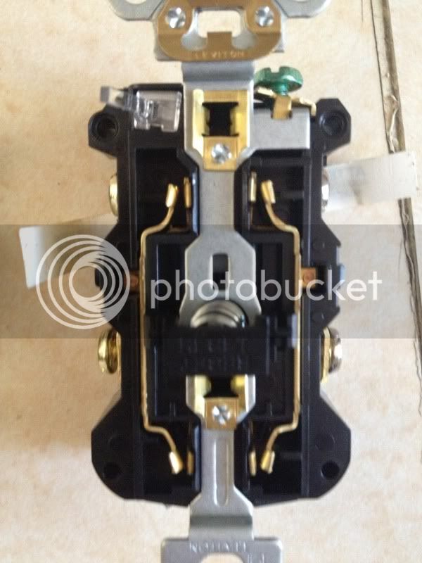
So when you say cut the tab on the receptacle, are you talking about the gold plated metal part running down both sides of the receptacle in this picture?
I finally have some time to assemble this thing! Seems like such a long time since I last posted here.
So when you say cut the tab on the receptacle, are you talking about the gold plated metal part running down both sides of the receptacle in this picture?
I think you're looking at the wrong part. Please send a side view of the receptacle so I can circle what I'm talking about in MS paint or other crude fashion. Make sure you take a picture of the hot side or the side with gold screws on the left in your picture. You want to break the "bridge" between the two screw terminals on the hot side (gold screws). You do not need to break the bridge on the neutral side because it's a common line. If you're having trouble visualizing what I'm talking about check out the following video.
http://video.about.com/electrical/How-to-Wire-Split-Outlets.htm
Edit: In the video, the narrator is talking about making one half of the outlet switched, but that part doesn't really apply to you. In fact, technically you are making both halves switched, just by SSR and not a manual flip switch.
misled_drummer
Well-Known Member
I think you're looking at the wrong part. Please send a side view of the receptacle so I can circle what I'm talking about in MS paint or other crude fashion. Make sure you take a picture of the hot side or the side with gold screws on the left in your picture. You want to break the "bridge" between the two screw terminals on the hot side (gold screws). You do not need to break the bridge on the neutral side because it's a common line. If you're having trouble visualizing what I'm talking about check out the following video.
http://video.about.com/electrical/How-to-Wire-Split-Outlets.htm
Edit: In the video, the narrator is talking about making one half of the outlet switched, but that part doesn't really apply to you. In fact, technically you are making both halves switched, just by SSR and not a manual flip switch.
Here's a picture. Thanks for the video.
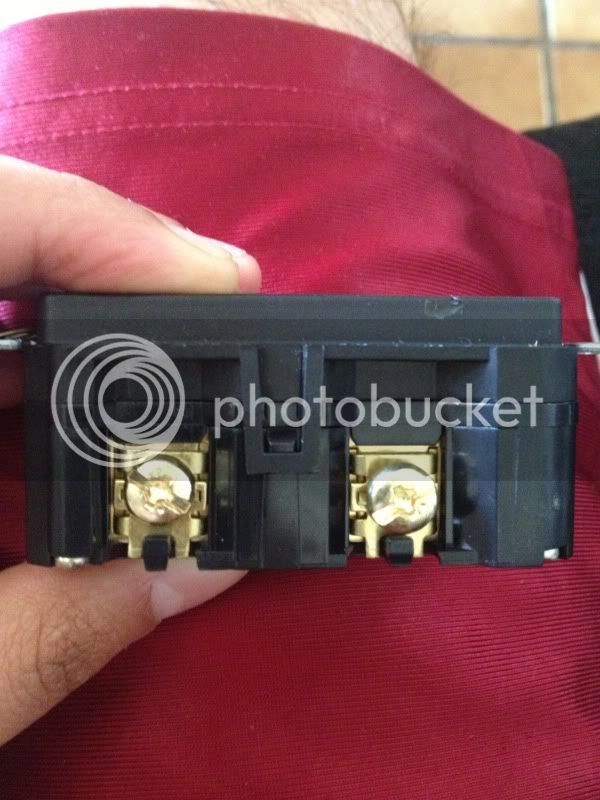
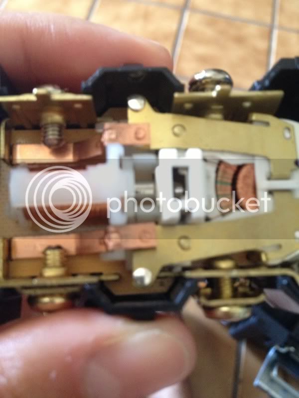
Edit: Here's the inside. Looks like they are not connected.
Carlscan26
Well-Known Member
misled_drummer said:Here's a picture. Thanks for the video.
Edit: Here's the inside. Looks like they are connected.
Get a different outlet.
HDIr0n
Well-Known Member
Get a different outlet.
Exactly, usually there is a jumper that connects the two screws on the side that allows you to remove it and have the outlet switched separately. Get a different outlet that has that and you will be golden.
misled_drummer
Well-Known Member
Exactly, usually there is a jumper that connects the two screws on the side that allows you to remove it and have the outlet switched separately. Get a different outlet that has that and you will be golden.
Damn I was hoping this wasn't the case. I bought the GFCI a few months ago, and I think I am out of the return date. Oh well.
Edit: I managed to get them to exchange the outlet for me. Thanks guys.
k_mcarthur
Well-Known Member
That's a GFCI outlet, I would toss it since you've opened it up and it's tripping reliability can't be guaranteed. The outlet that has the tabs to separate the top and bottom plugs are the normal $.69 outlets. On the gold screw side its obvious the tab they are talking about in between the two screws. Also when dealing with power and water, make absolute sure your power source is properly grounded and GFCI protected. If in doubt, as it seems may be the case, hire an electrician. The right one may even help for some beer, I know I have!
Wrecked
Well-Known Member
I've read a lot of this thread, but not all of it. So, if this question has been asked and answered, my apologies.
I'm confused about the placement of the temp sensor downstream from the heating element. If I'm reading the schematics correctly. The inlet is on the heating element end of the RIMS tube and the temp probe is on the return/outlet end of the RIMS tube, right? With the temp probe located directly downstream from the heating element, how do you get an accurate mash temp. It seems like the probe being directly inline with the just heated liquid would cause an error in the actual mash tun temperature.
I know a lot or brewers have great success with this design. I'm just fuzzy on how, lol.
Wrecked
Yes, the sensor needs to be downstream of the heating element. There are much smarter guys than me in this forum that have the explanation. (I read 'um too). I mounted my tube vertically with the heating element at the bottom so its always submerged. If not, it will melt down. Trust me, its not a pretty picture. The inlet from your MT comes in right above it and fills the tube. There is a difference in temp between what the controller says and what's in the tun, at least til the system stabilizes. Be sure to auto tune your controller in the temp range you mash at and the controller will learn how your system responds giving very accurate temps that maintain well after that. I'm learning by trial and error like you, but its definitely worth it. A well calibrated thermometer is your friend. I made the mistake of taking what the controller said at face value without verifying accuracy. Dumb mistake.
Wrecked
Well-Known Member
Thanks for the response Jay.
I don't doubt the effectiveness of a RIMS. I just couldn't wrap my head around the temp probe location and temp accuracy.
I guess I'll just have to finish my RIMS and find out for myself")
I don't doubt the effectiveness of a RIMS. I just couldn't wrap my head around the temp probe location and temp accuracy.
I guess I'll just have to finish my RIMS and find out for myself
I'm confused about the placement of the temp sensor downstream from the heating element.
I've gotten good results with the heating element downstream from the temp sensor, as documented in this thread.
The system diagram and test run results are shown below. I'm getting +/- 1F from set point, measured in the kettle; seems pretty good to me. For my system, I like having the heating element downstream because I can have the RIMS tube connected directly to the kettle in by BIAB setup, eliminating one hose.
Given the discussion this topic seems to bring, I plan to capture data from another test run after my next brew day when all my gear is out. I'll add a hose, and have the temp sensor downstream from the heating element. It will be interesting to see which approach yields the best performance in terms of temperature stability and responsiveness. Data-driven brewing! :rockin:


misled_drummer
Well-Known Member
I think you're looking at the wrong part. Please send a side view of the receptacle so I can circle what I'm talking about in MS paint or other crude fashion. Make sure you take a picture of the hot side or the side with gold screws on the left in your picture. You want to break the "bridge" between the two screw terminals on the hot side (gold screws). You do not need to break the bridge on the neutral side because it's a common line. If you're having trouble visualizing what I'm talking about check out the following video.
http://video.about.com/electrical/How-to-Wire-Split-Outlets.htm
Edit: In the video, the narrator is talking about making one half of the outlet switched, but that part doesn't really apply to you. In fact, technically you are making both halves switched, just by SSR and not a manual flip switch.
Finally got someone to help me wire this thing. It took longer than expected, but we wired it yesterday.
I just had a few questions before I tested this thing.
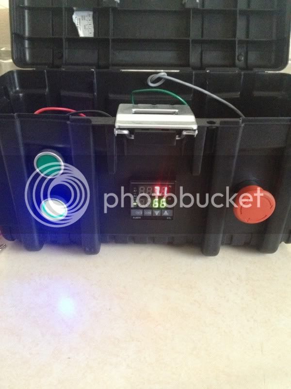
1. Once I set the Sn setting on the PID (2352) to 21 (indicating that I am using an RTD probe according to the Electric Brewery) I got this error:
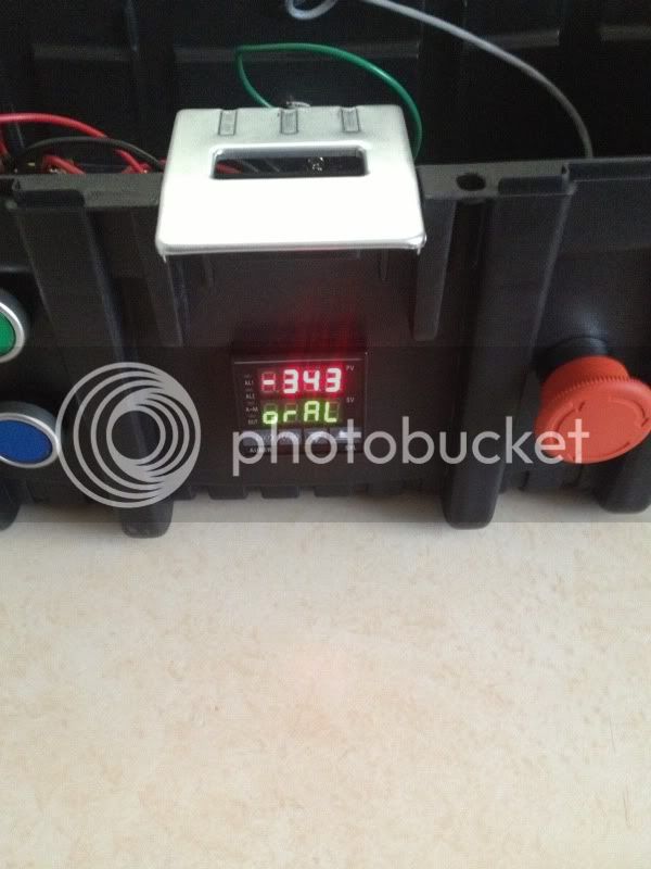
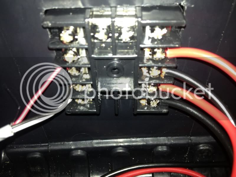
I was not getting an accurate reading before changing the setting. The PID showed a temperature, but it never really changed much beyond plus or minus 72. I have the RTD hooked up to 3-5 on the PID (left side of the pic). According to Derrin, the sensor is on the white and black wires, hooked up to terminals 4 and 5 respectively. I wanted to check whether switching these wires will solve my problem before I mess with this guy's wiring.
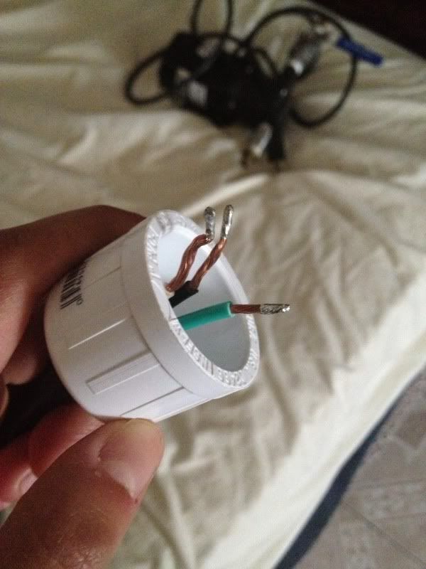
2. As far as grounding the water heater element, how should I go about doing this? I have the cord going into a PVC cap that I am going to JB weld onto the heater element. Should I just leave the ground wire hanging?
3. Finally, According to the Electric Brewery, I should run the PID on auto in order to calibrate it with my system. Is there anything else I need to do to set this up?
Thanks so much for all your help guys. I'm almost there and excited to use this thing.
misled_drummer
Well-Known Member
PVC Cap picture:
Similar threads
- Replies
- 1
- Views
- 525
- Replies
- 112
- Views
- 5K
- Replies
- 7
- Views
- 490
- Replies
- 9
- Views
- 811
