2/6/2016 update - part 2
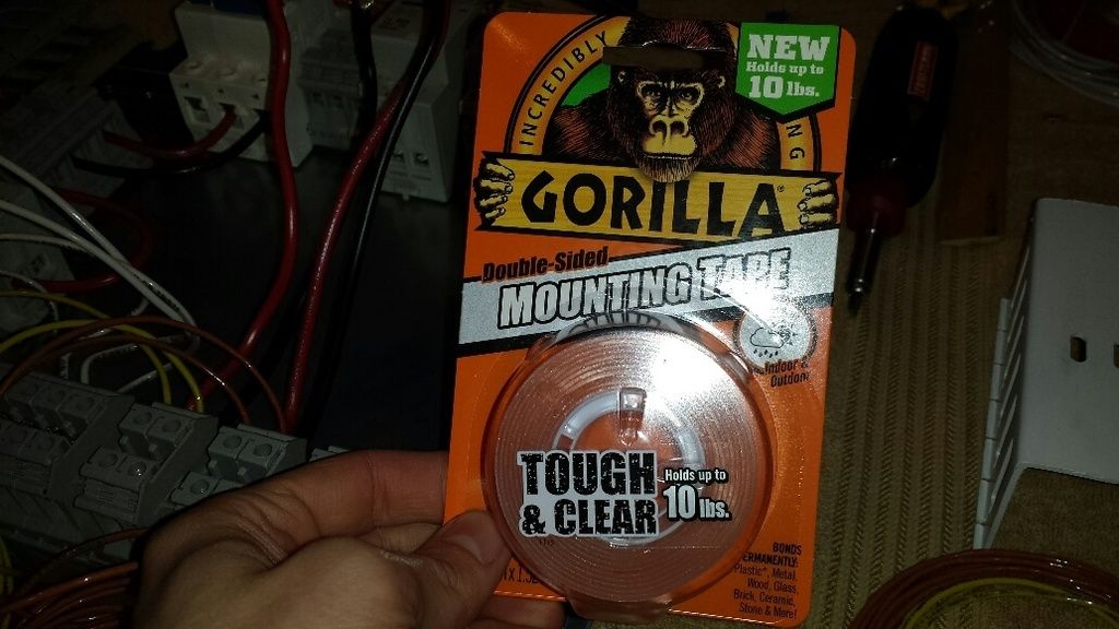
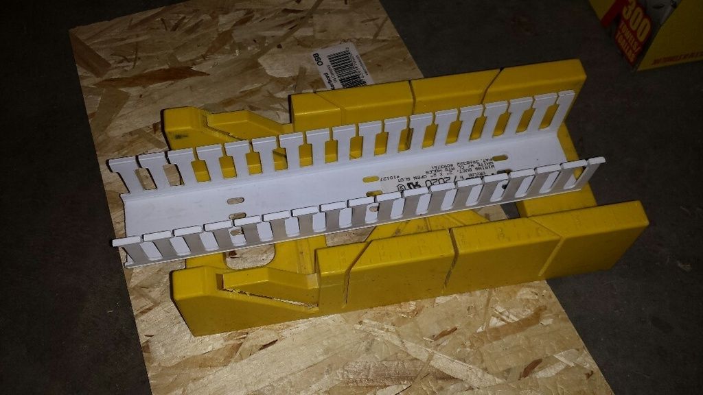
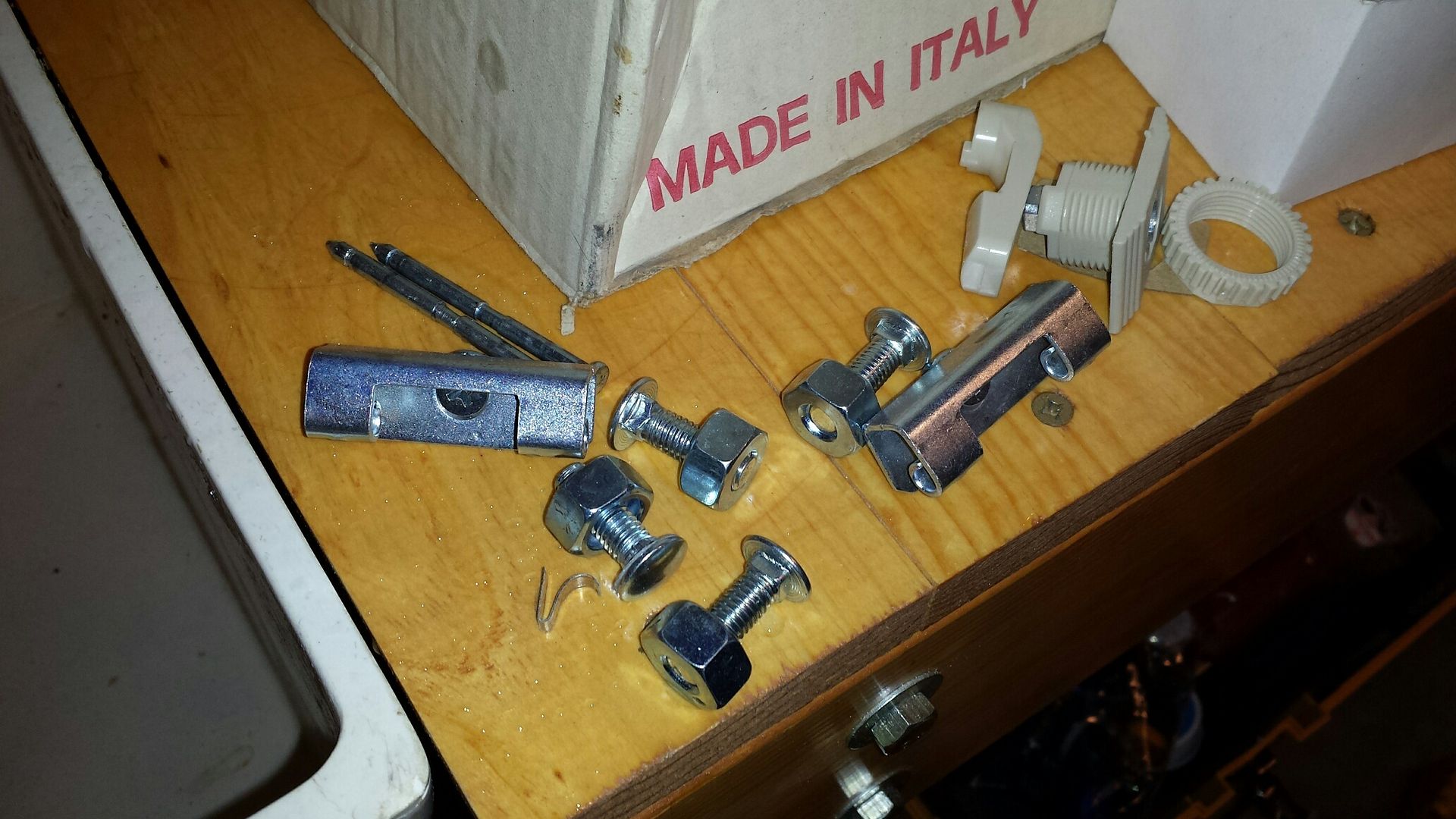
so the more i looked at it, the more i realized how difficult it was going to be to get some nice, neat, straight wiring installation. and i noticed how i was running wires down some 'highways' anyway. i had snagged some wire duct from work with the thoughts of using it in my build but after taking a look at it, i thought it would look weird and didn't have a great way to attach the duct to the door/back panel. i made a game-time decision to start using it. first step was how to attach the duct so i wandered down to menards to see what might be available. and then i saw it:
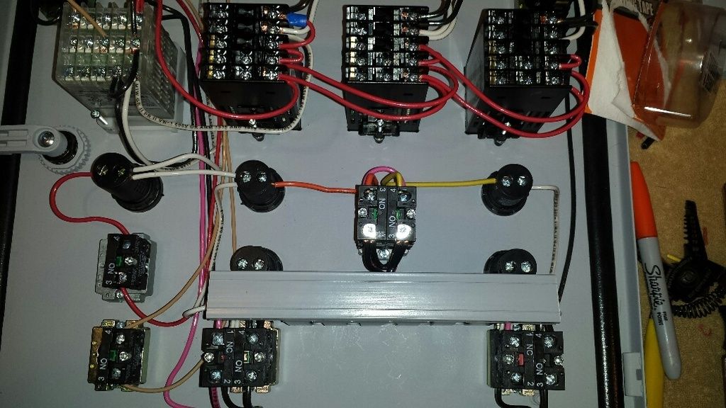
this stuff would work perfectly. i don't have to hold any weight but i want something that was tough and wouldn't fall out. i decided to start with the back panel and cut some duct to length:
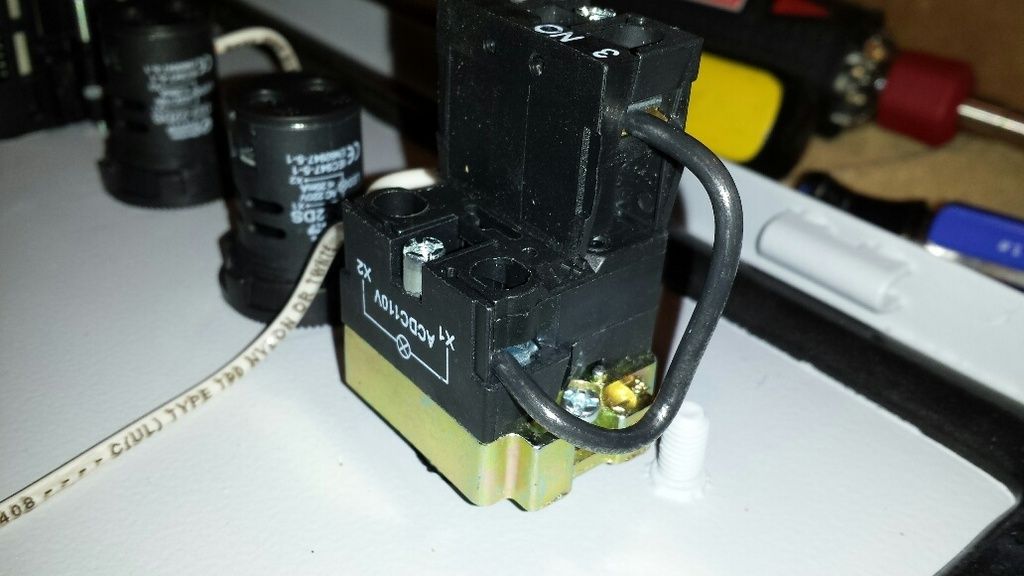
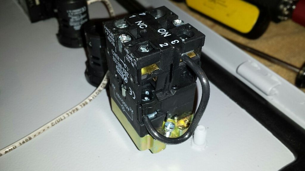
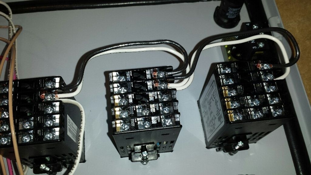
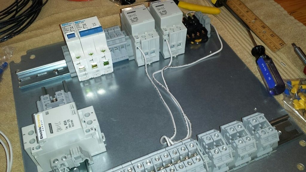
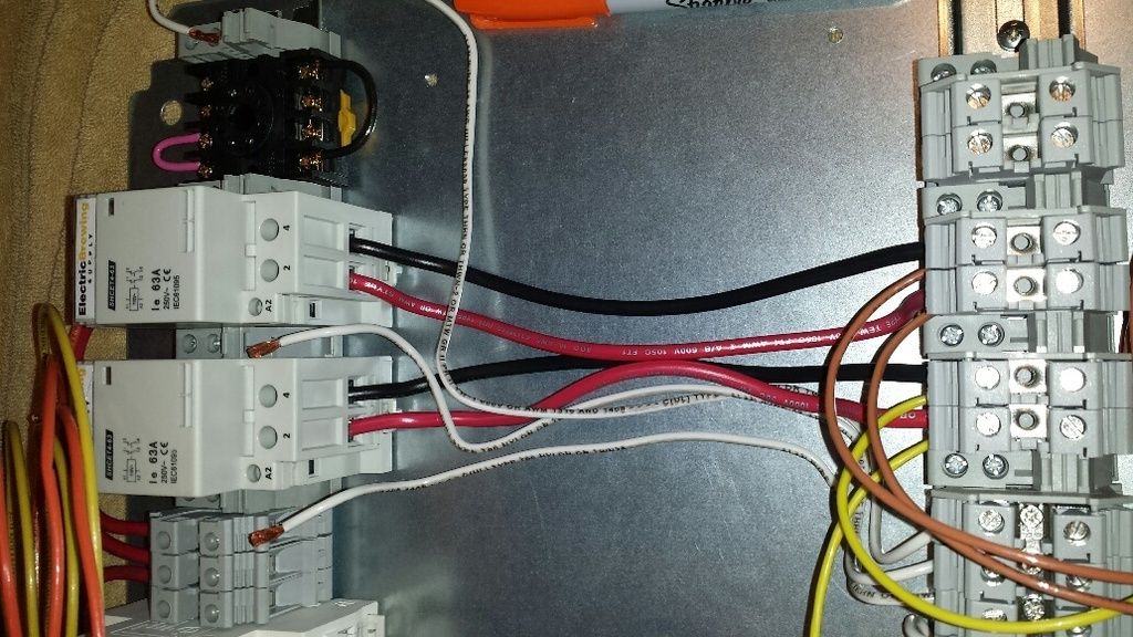
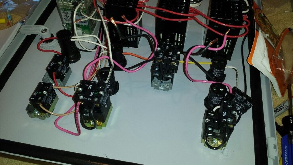
unfortunately, i was going to have to undo some wiring. a 'before' shot, with some wires disconnected:
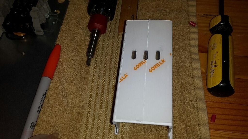
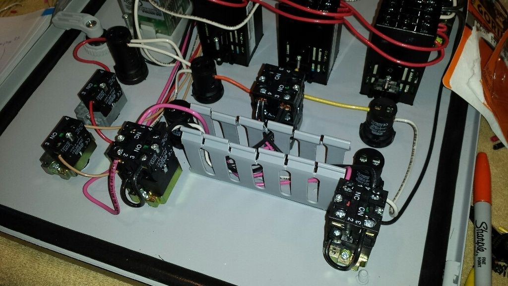
tape applied to the back of the duct:
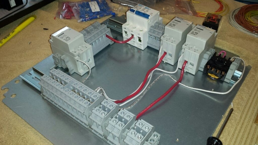
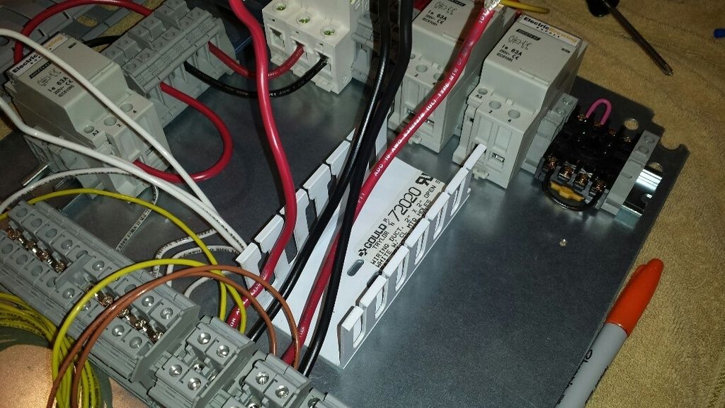
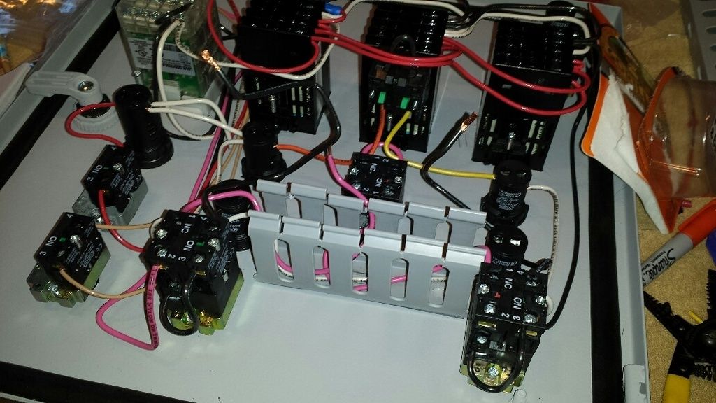
a progress shot:
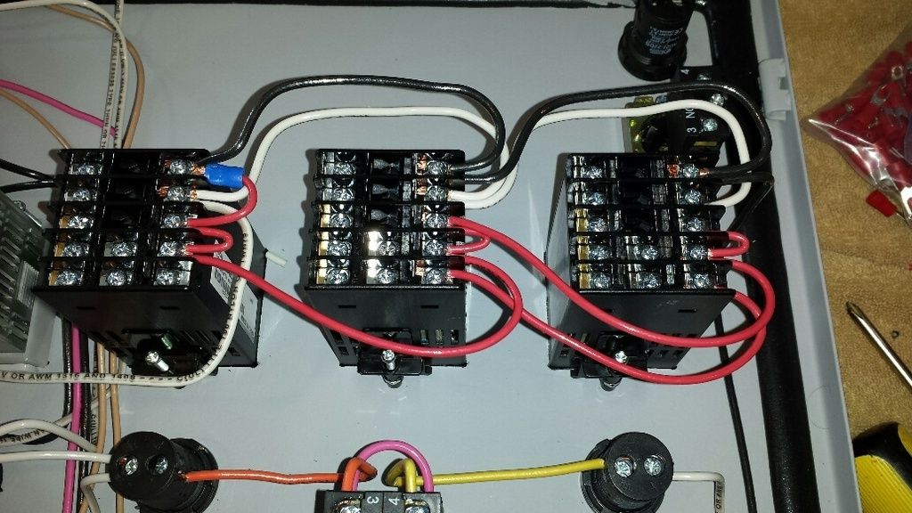
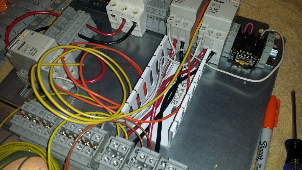
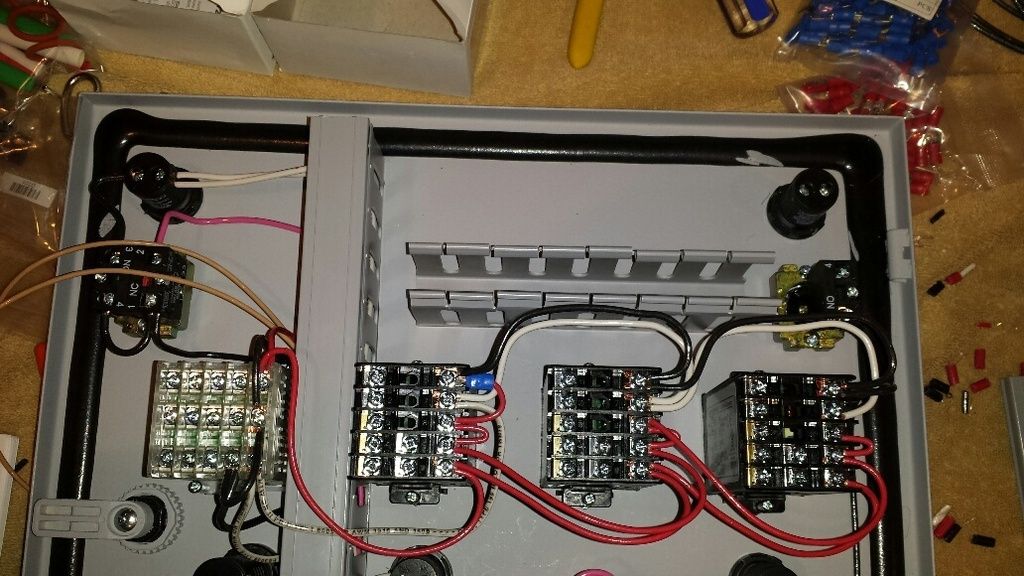
all the wires in:
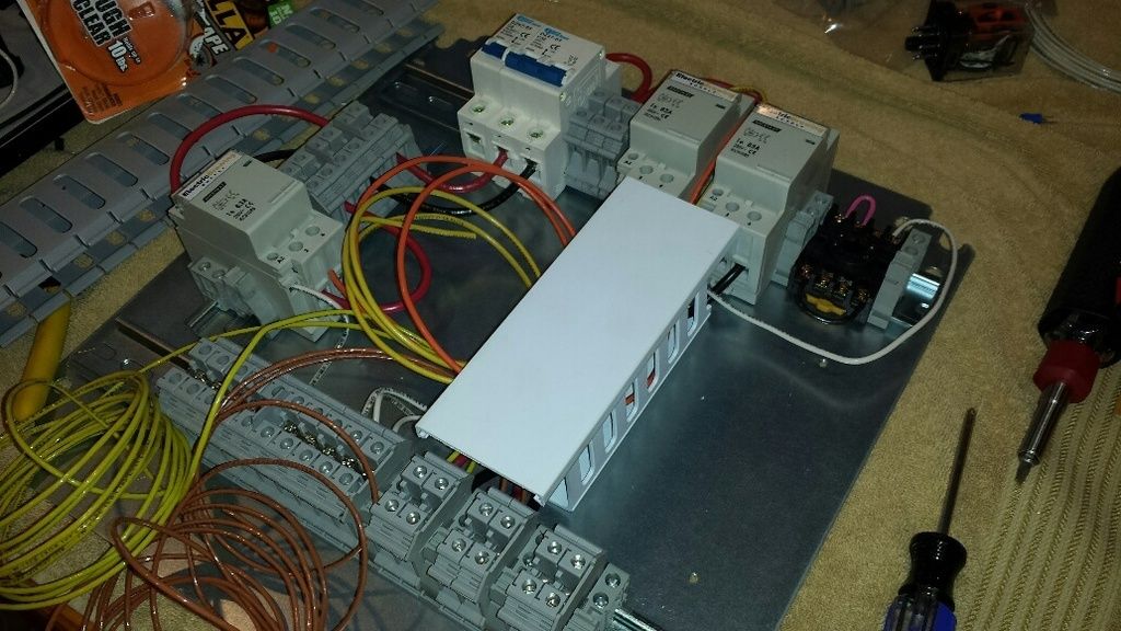
and with the cover on:
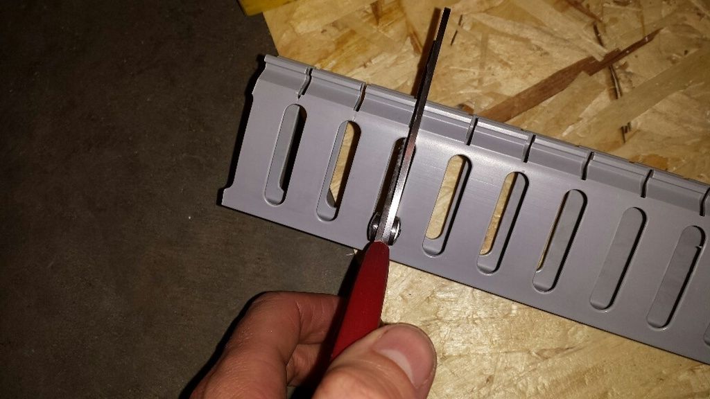
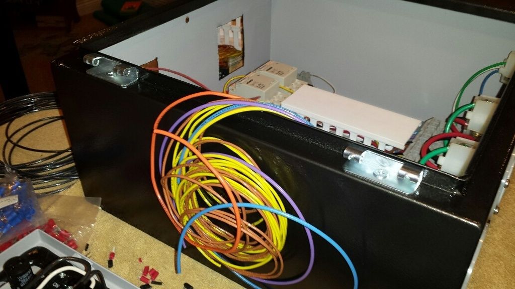
looks great! so i moved on to the door. i used a different type of duct for the door:
this stuff was a little annoying in that none of the ribs were cut so i had to bust out the scissors:
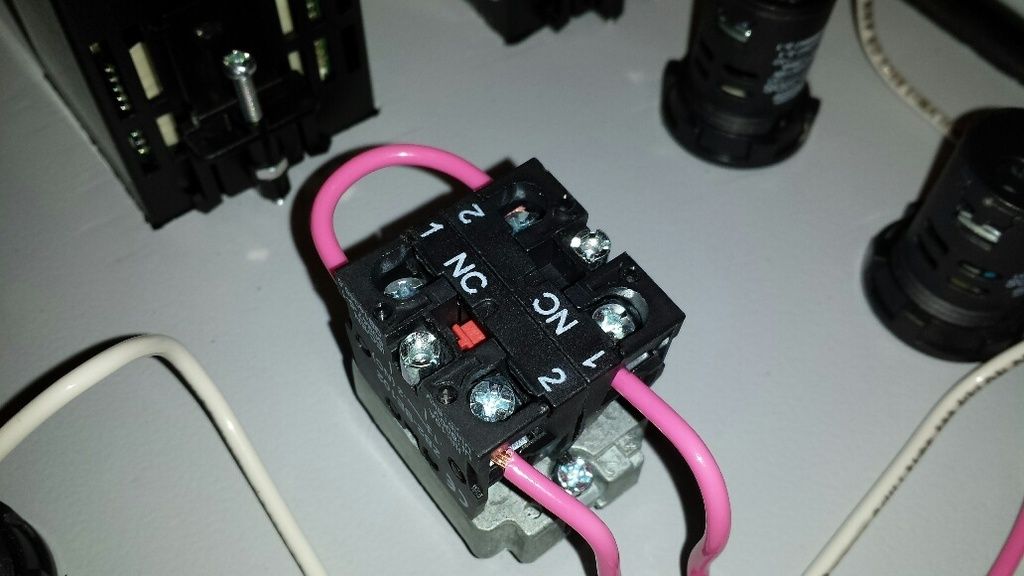
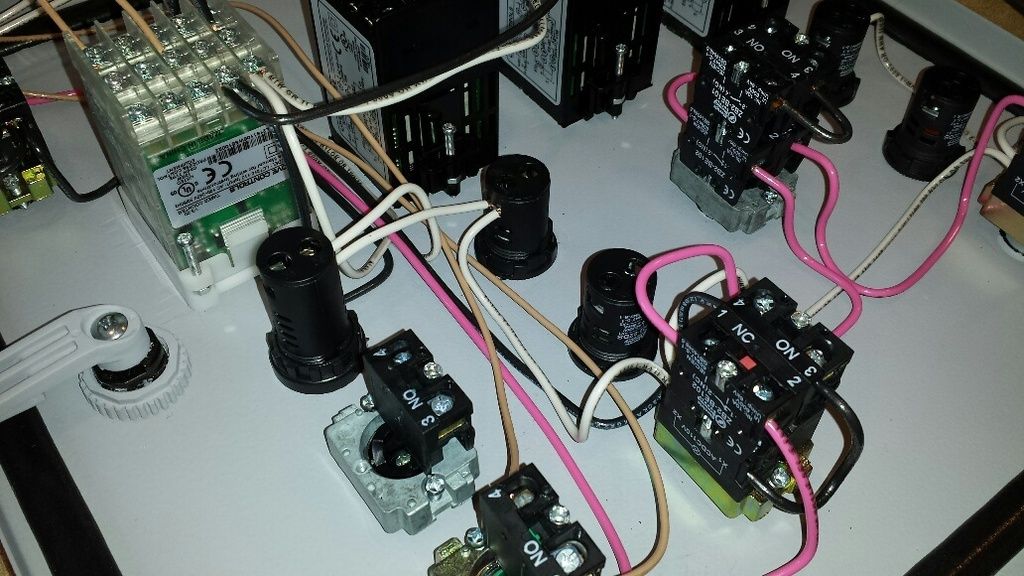
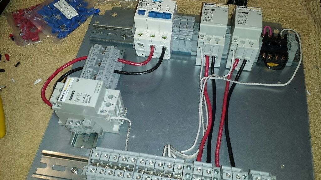
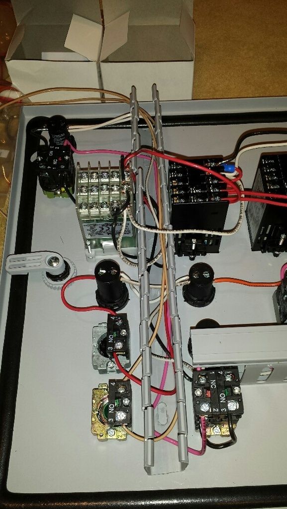
same as before, disconnecting some wiring to accommodate the wire duct:
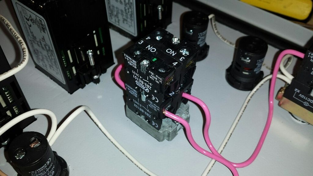
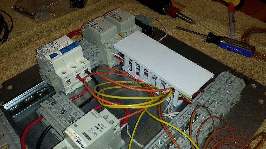
duct installed, some wire in place:
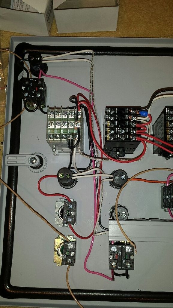
all wires in place:
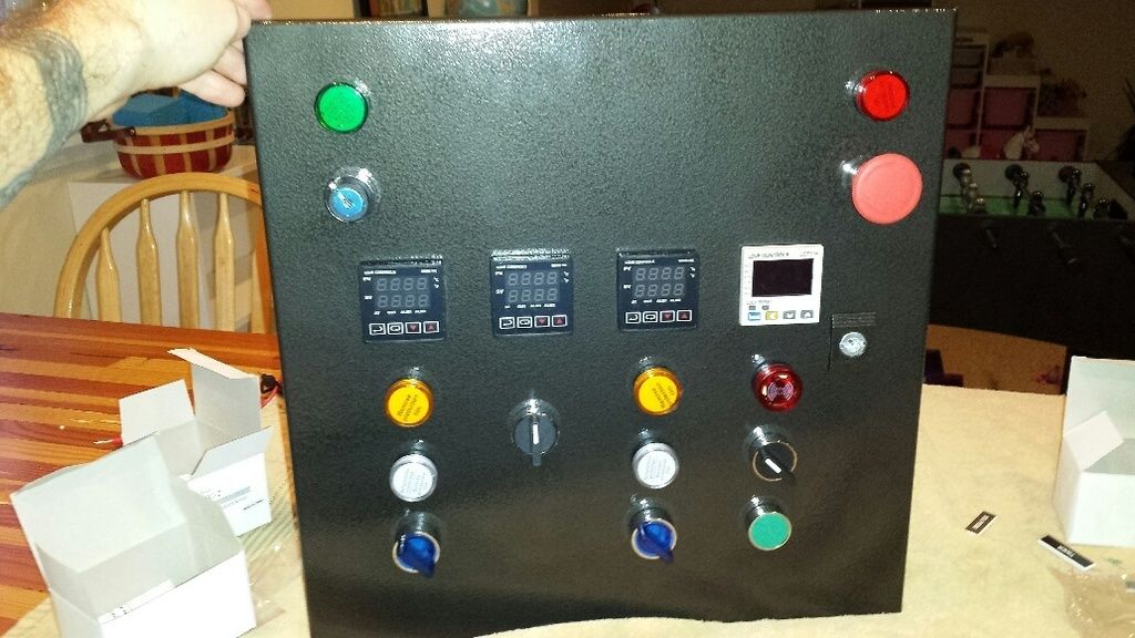
and with the lid on. even for this small bit of wiring, the look is much cleaner:
next place for duct was the other 'highway' on the door:
some of the wiring in place:
cover on, plus some duct in place for the temp probes and ssr wires:
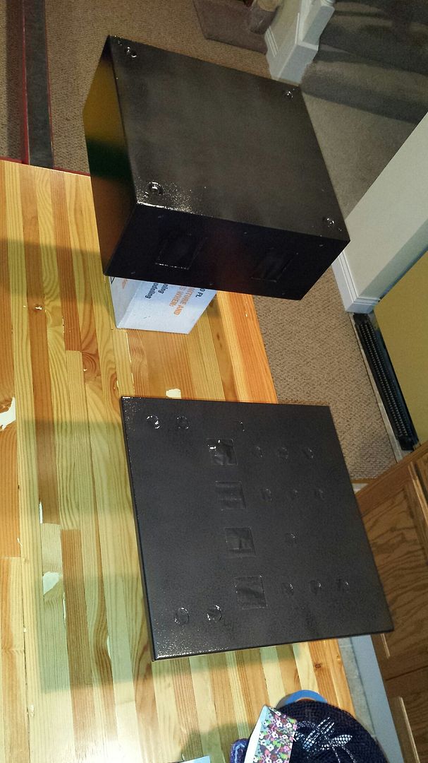
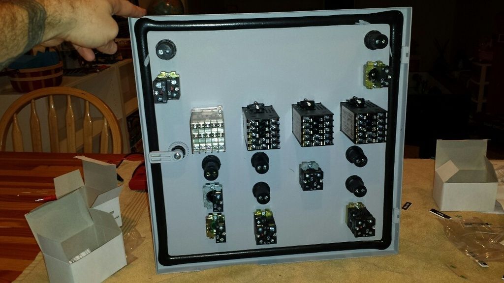
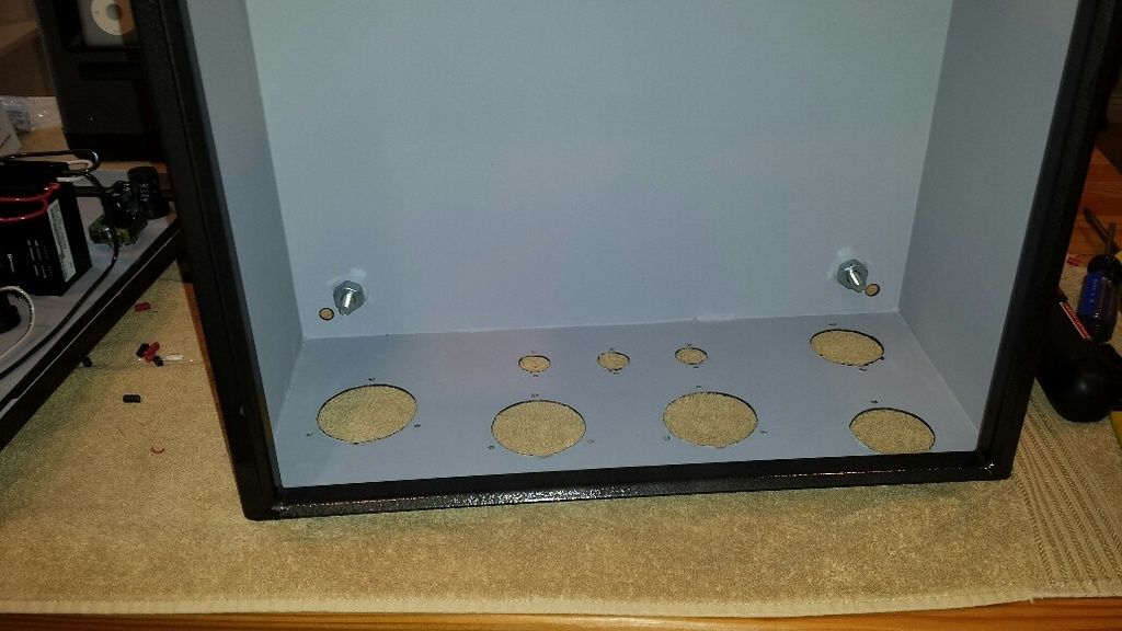
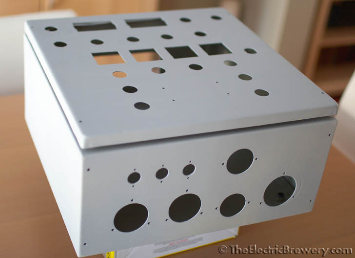
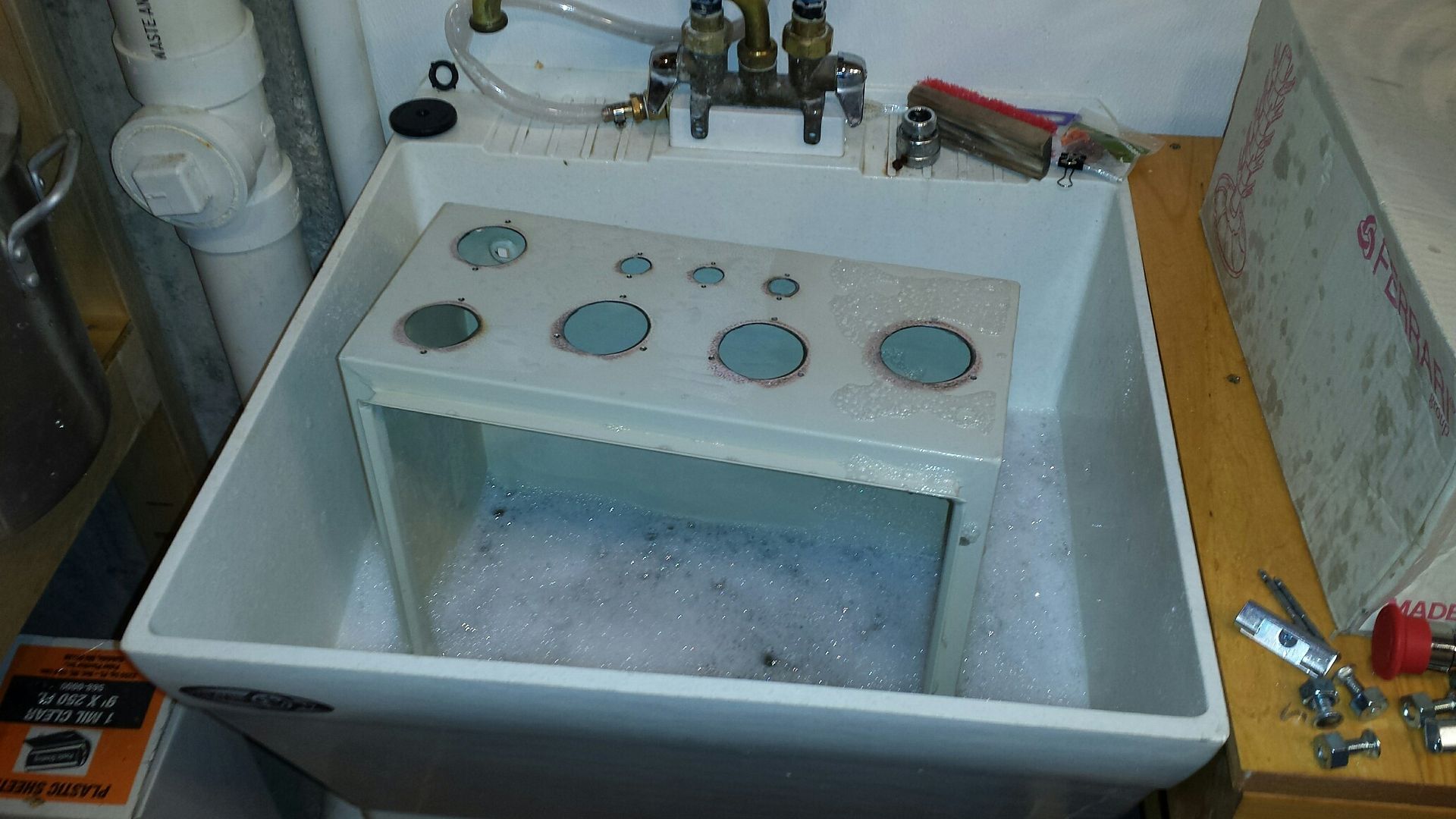
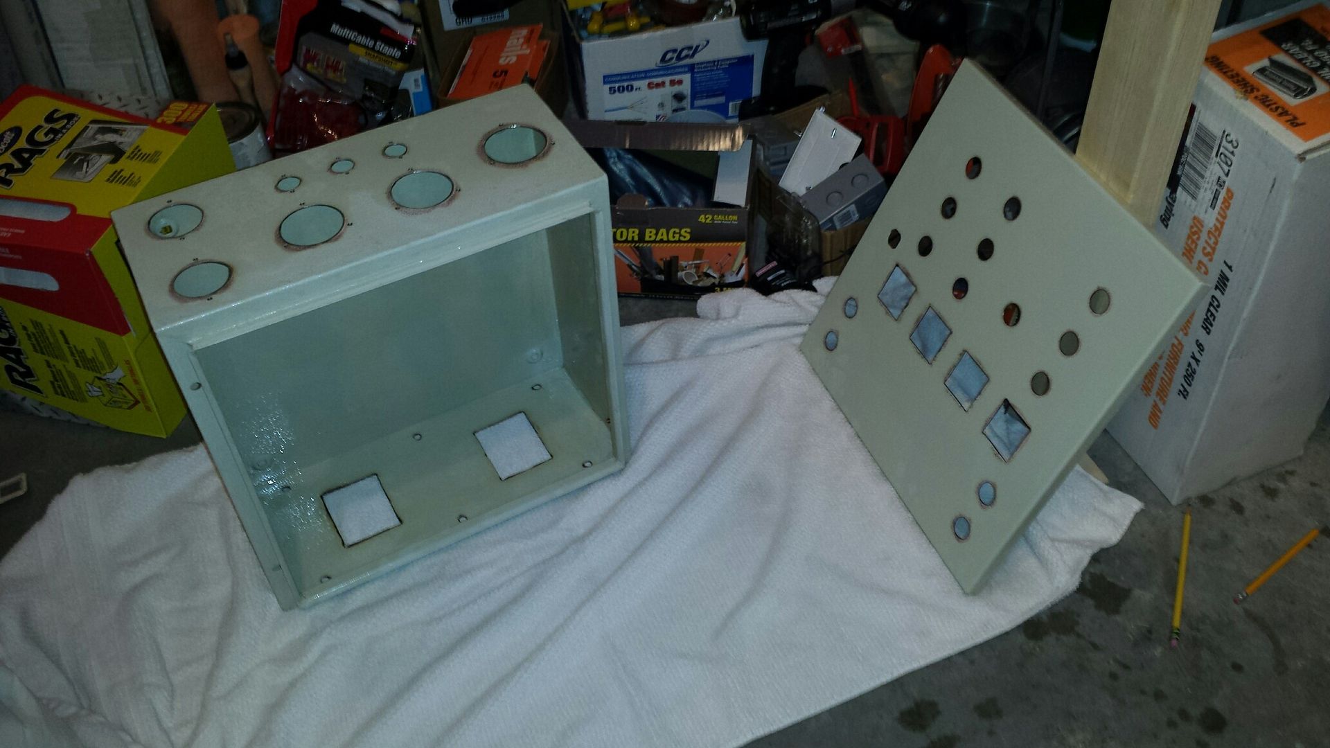
with the back panel wired up, time to mount it in the enclosure. studs re-installed for mounting the back panel:
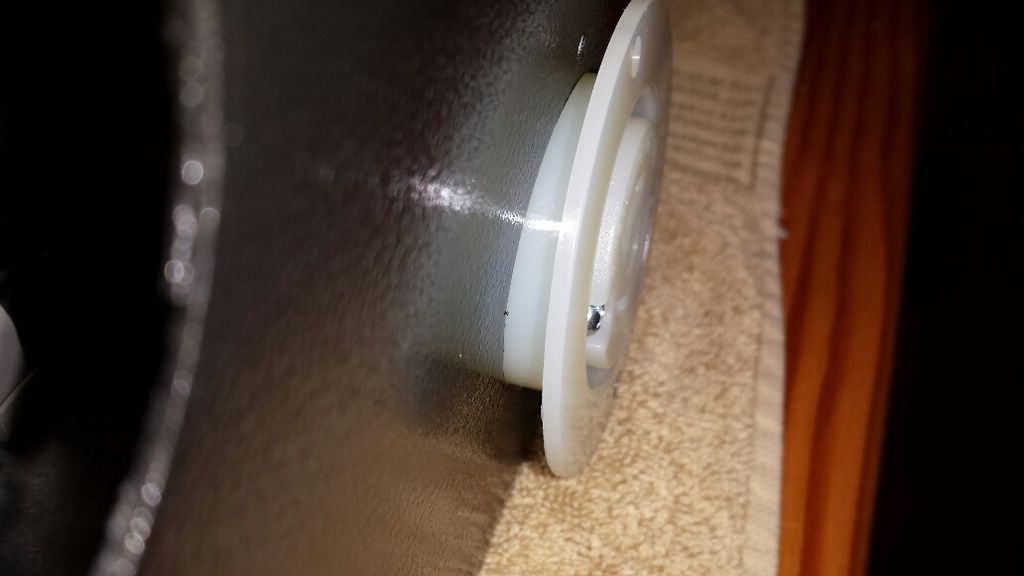
back panel installed, time to move on to the outlets at the bottom of the enclosure. started with one for the pump, noticed a problem when i lined up the holes on the receptacle with the taps on the enclosure:
d'oh, the receptacle body hits the mounting posts for the back panel:
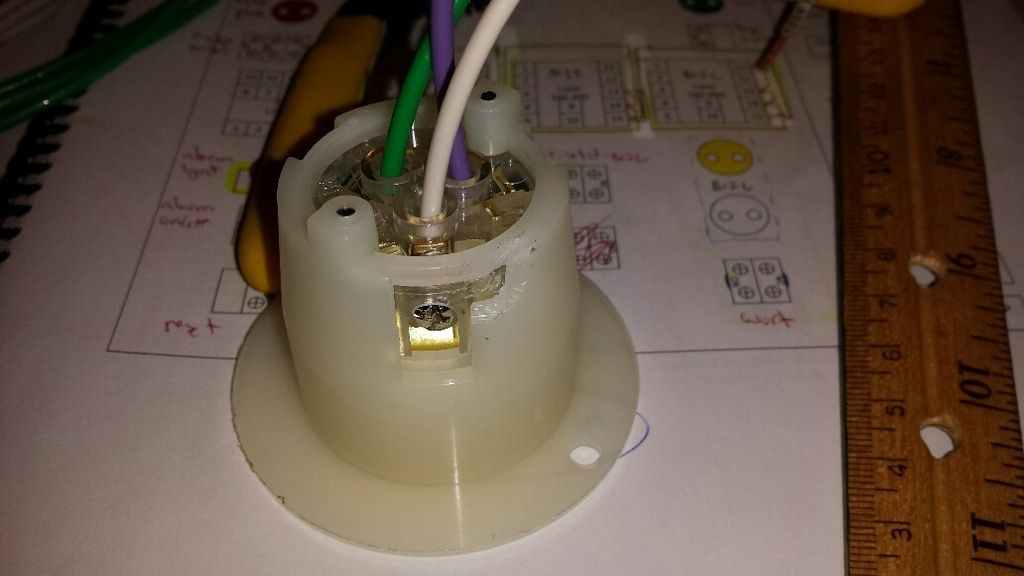
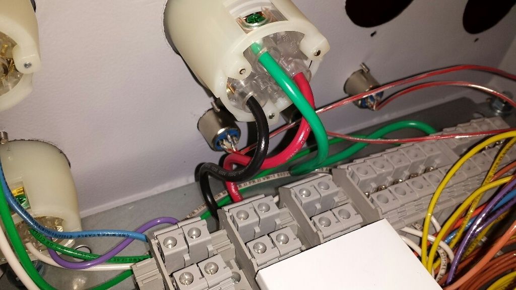
a little trimming with a utility knife and i was back in business. i also terminated the wires in the receptacle before mounting it, no way to get to all the terminal screws otherwise. green is ground, white is neutral and the purple is the line conductor for the wort pump (more color coding):
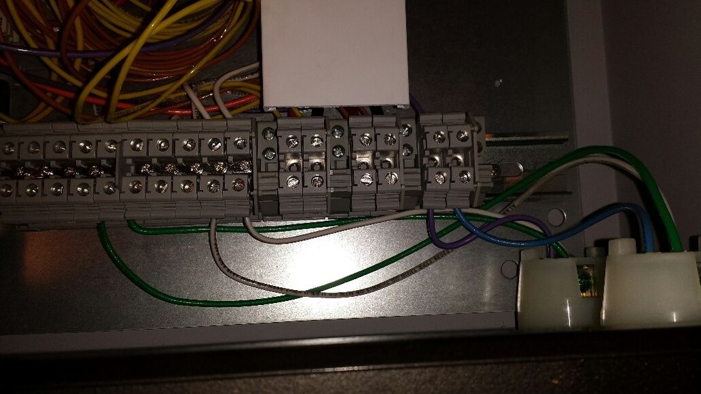
wiring from the receptacles to terminal blocks (water and wort pump):
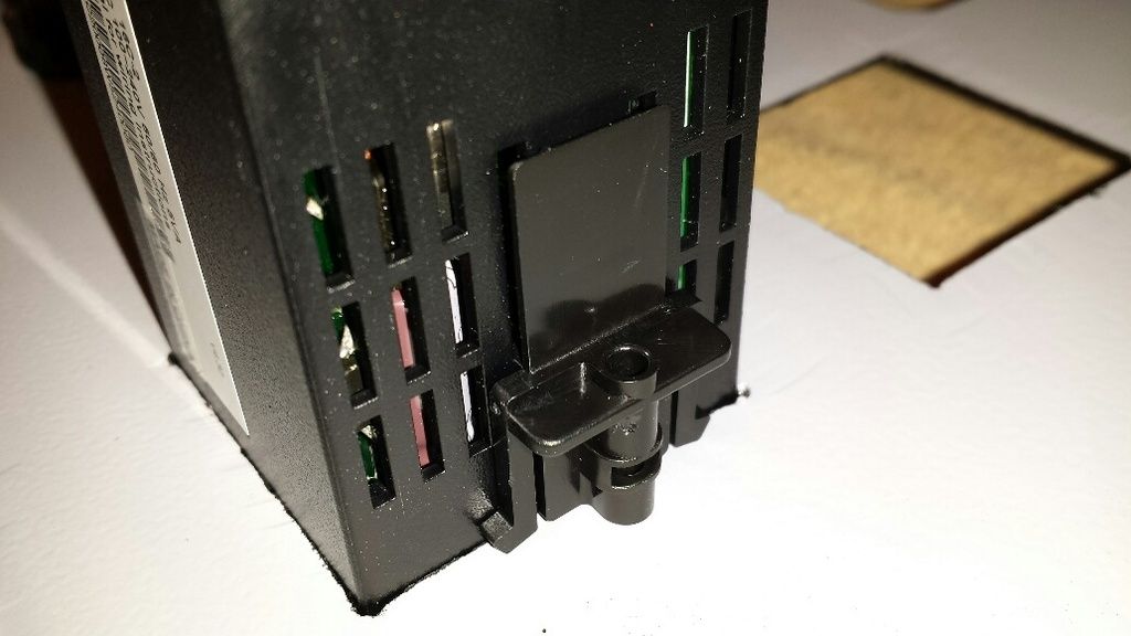
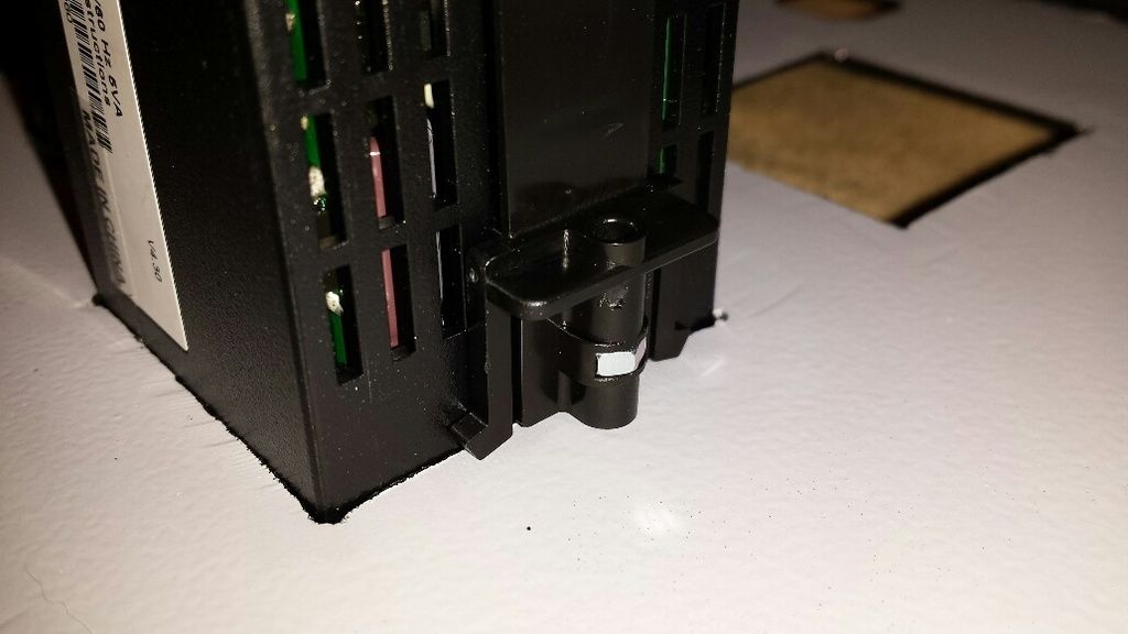
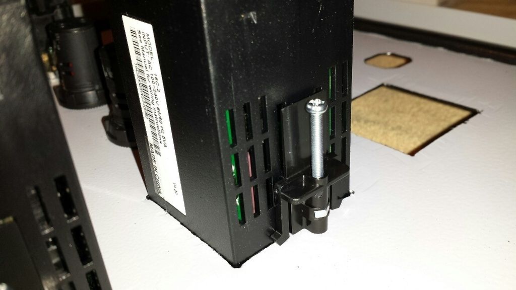
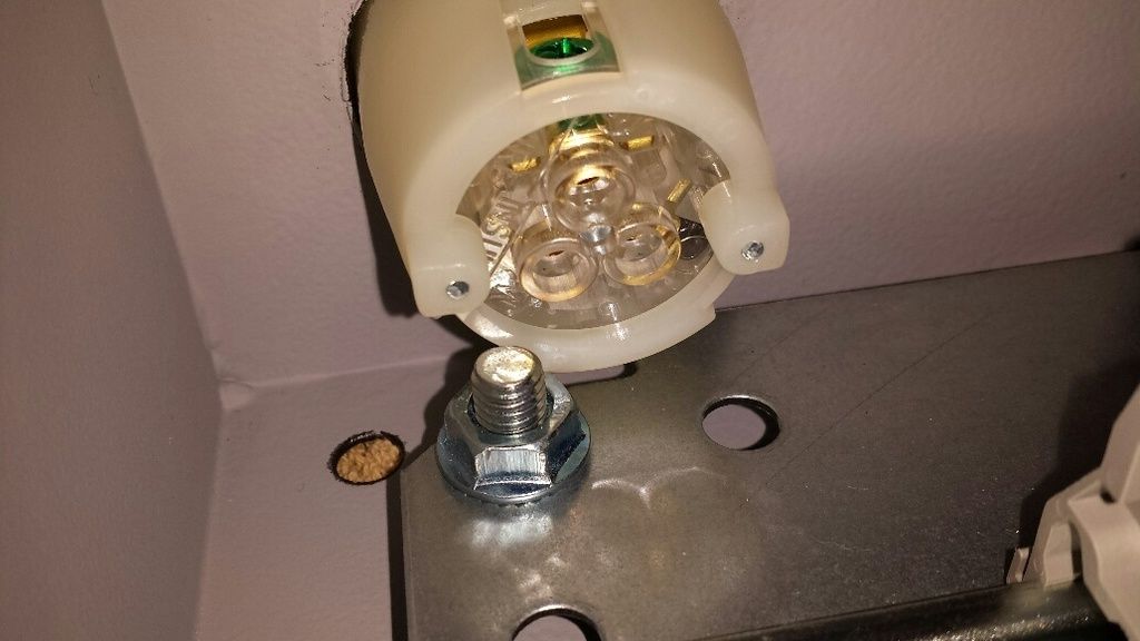
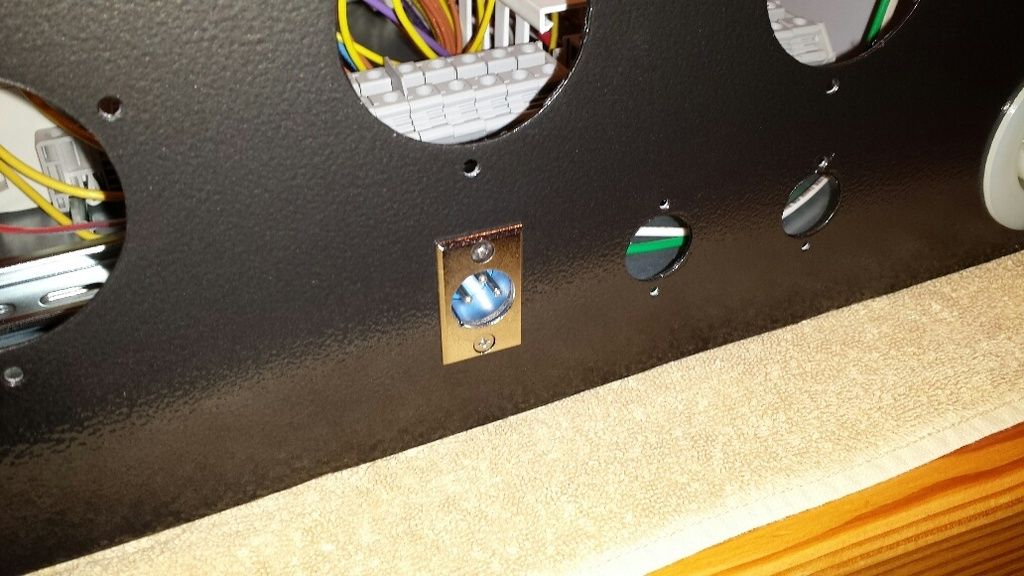
temp probe connector mounted. mounting holes were tapped, just had to thread a screw in (included), no need for a nut:
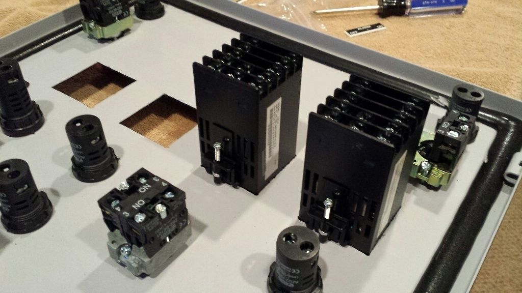
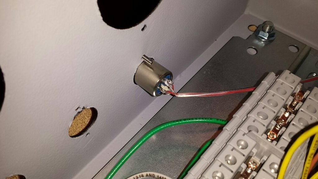
all three mounted. each connector comes with about six feet of cable and has lug terminals on the end for each wire, very easy to hook up to the pids:
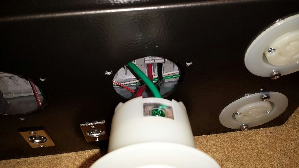
wiring up an element receptacle. it was easier to wire it without mounting and eyeball the connections to the terminal blocks through the hole in the bottom of the enclosure:
finished shot from the inside:
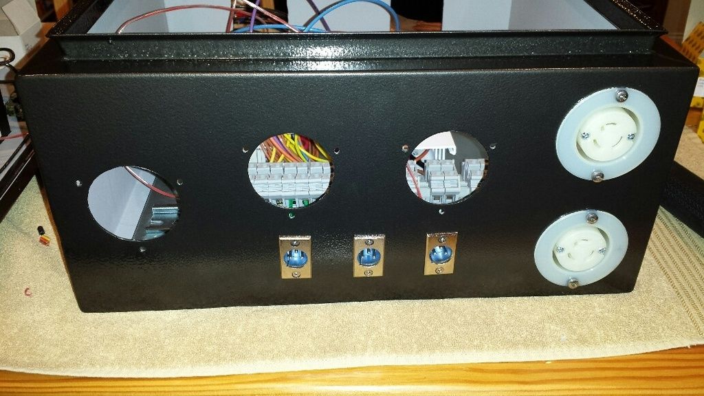
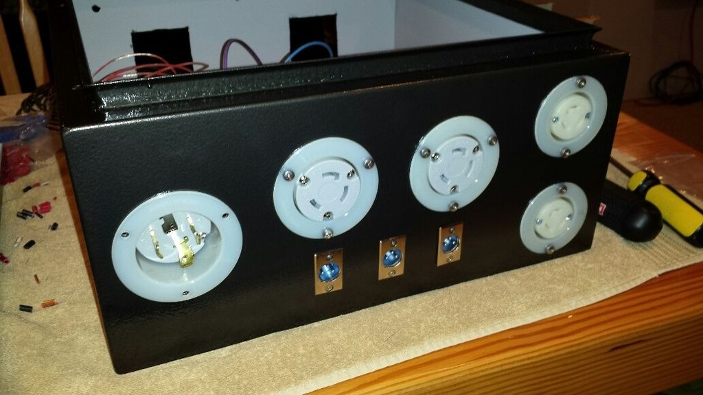
all the receptacles in place:
i also threw the hinges on:
had some breaks here and there but all told, a good eight hours of work today. i'm very glad i decided to wire this myself, have a much greater understanding of what everything is and how it is put together.

")