backyard sauna build

Homebrew Talk - Beer, Wine, Mead, & Cider Brewing Discussion Forum

Help Support Homebrew Talk - Beer, Wine, Mead, & Cider Brewing Discussion Forum:

This site may earn a commission from merchant affiliate links, including eBay, Amazon, and others.

itsnotrequired

Supporting Member
HBT Supporter
Joined
Sep 3, 2015
Messages
1,357
Reaction score
508
Location
Plover
okay, not really related to brewing but i built an outdoor backyard sauna a few years ago, figured i'd share the experience here.

in august of 2013, i visited my buddy out in seattle and discovered he had built an electric suana not in his basement but in his backyard. this was in an urban environment (ballard neighborhood, nw seattle) and was this awesome backyard oasis. i was visiting with my wife at the time and while we were all enjoying a round isweating on the bench, i remarked that we should build one of these at our place (central wisconsin). she just nodded her head and said 'totally'. so the game was on...

when we got back, i spent many an hour researching options. do i build one in our basement? do i get a kit or build it totally from scratch? or do we go with a detached structure in the backyard? and if so, do i go with the convenience of an electric heater or the authentic feel of a wood burning stove?

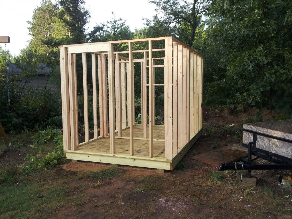
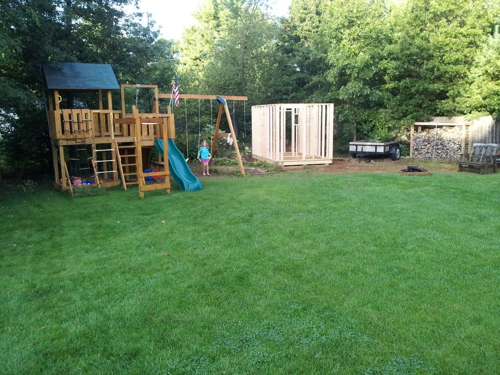
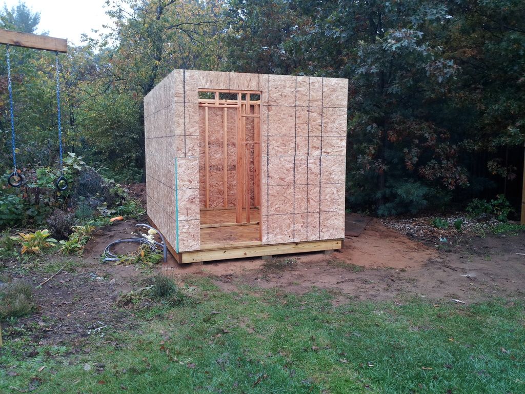
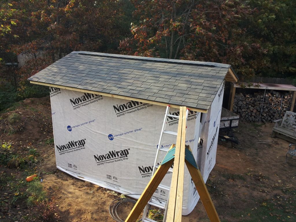
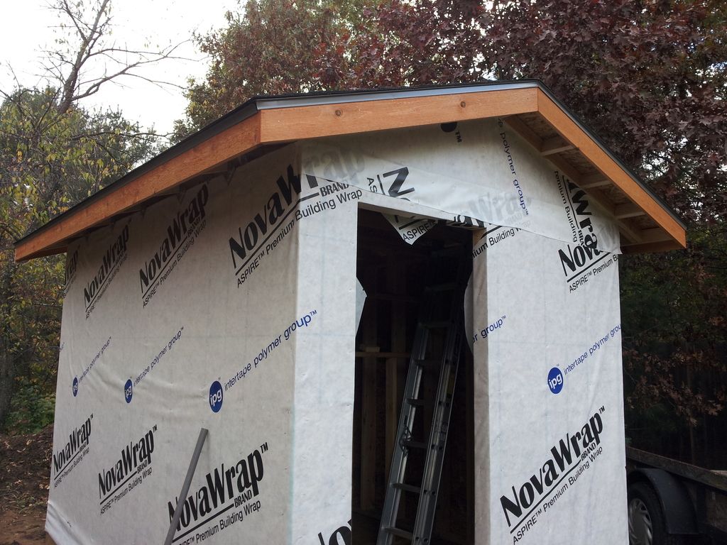
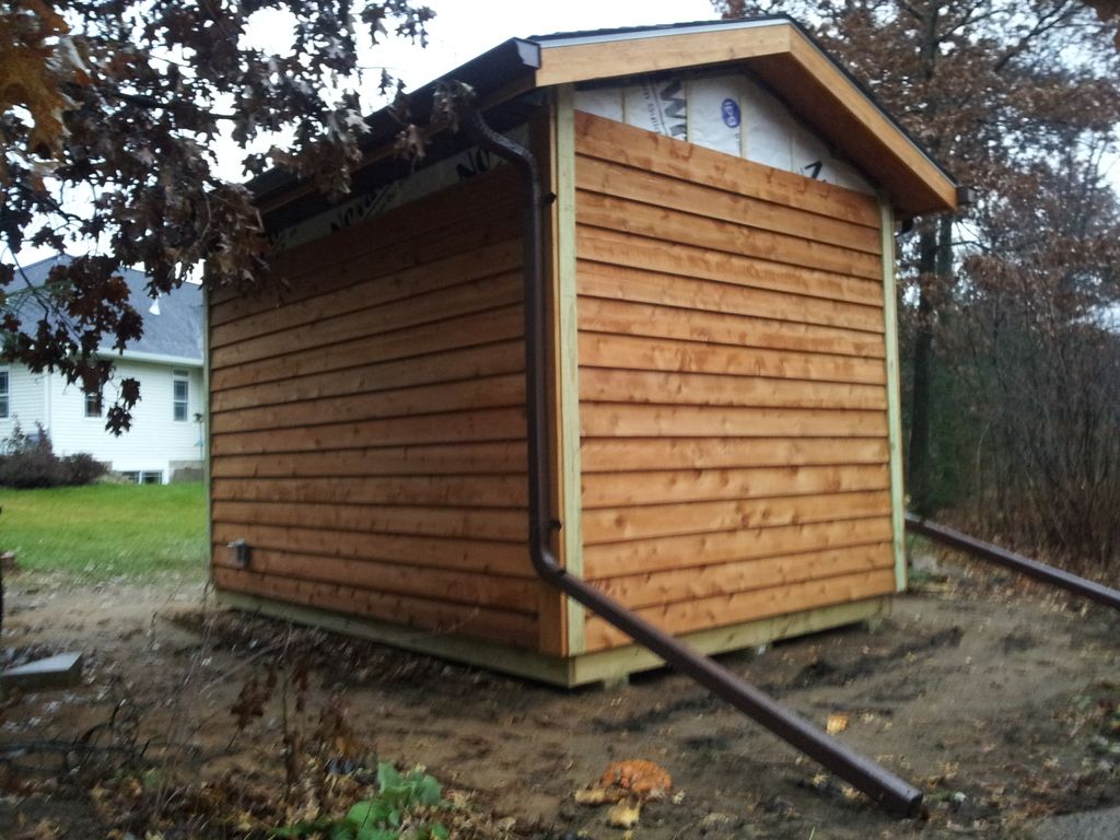
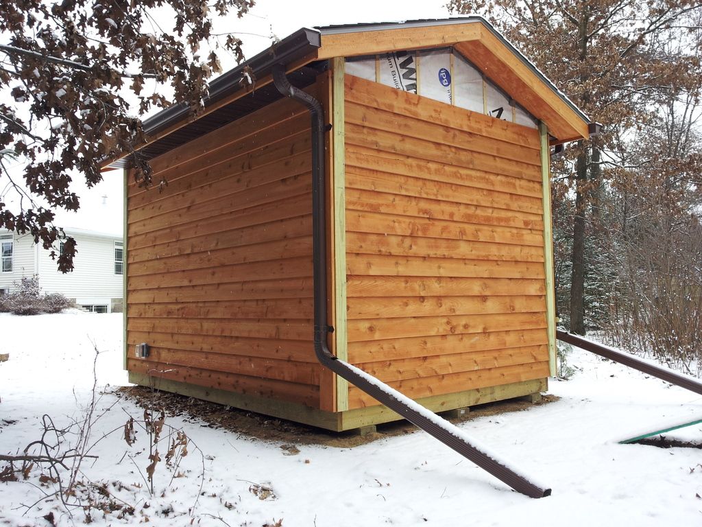
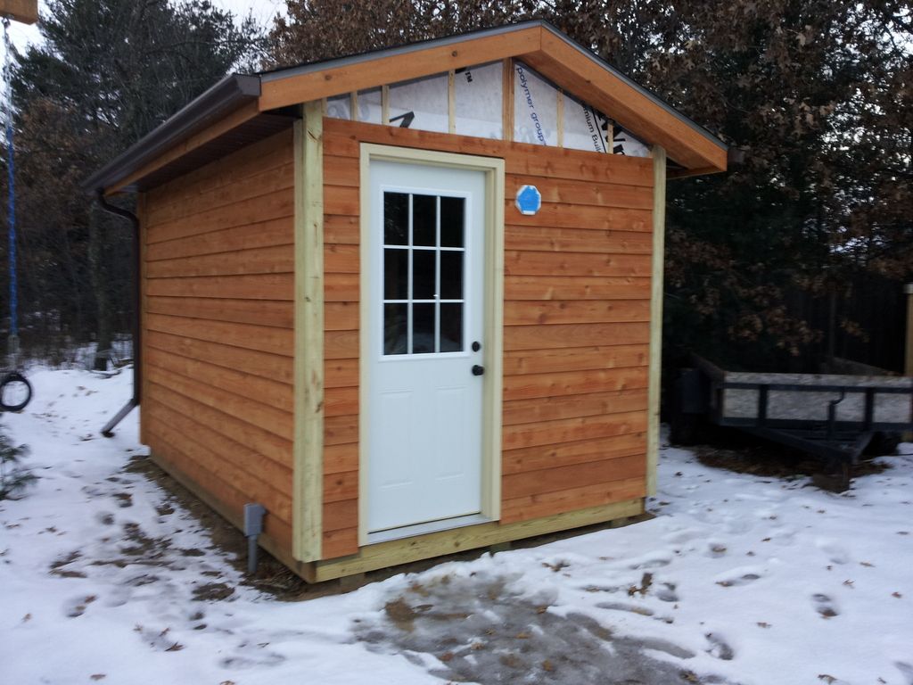
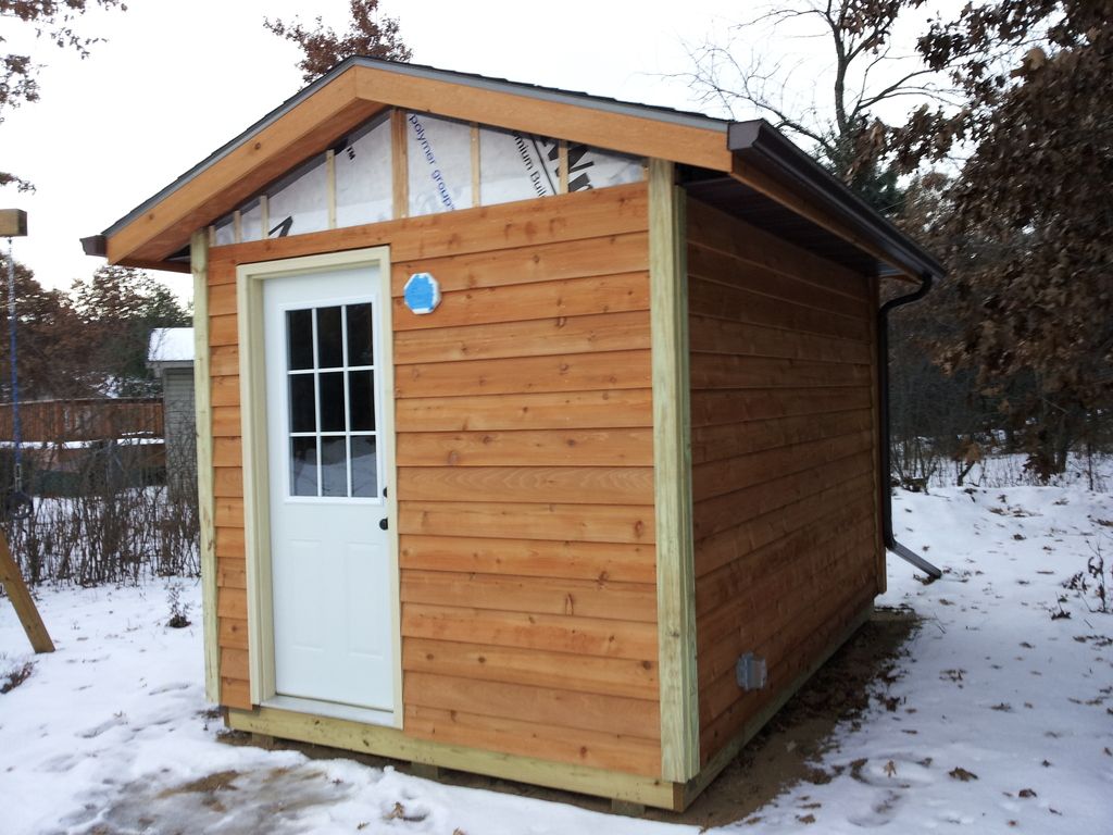
during my research, i stumbled upon an awesome website http://www.saunatimes.com/. this is a dude who built a wood burning sauna in his backyard in minneapolis (and this isn't some suburb, this is right in the city). i was fascinated by his 8'x12' detatched sauna structure. it included a hot room where you get all sweaty as well as a 'transition' or 'changing' room tat was a gateway between the outdoors and the hot room. in moderate temp seattle, a transition room really wasn't necessary but in central wisconsin, where temps can easily drop to -20 f, a transition room seemed like a must. the though of a sauna in the house just didn't seem right, with all the distractions of modern life. a detached structure was the way to go!

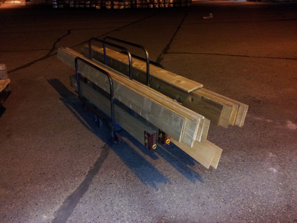
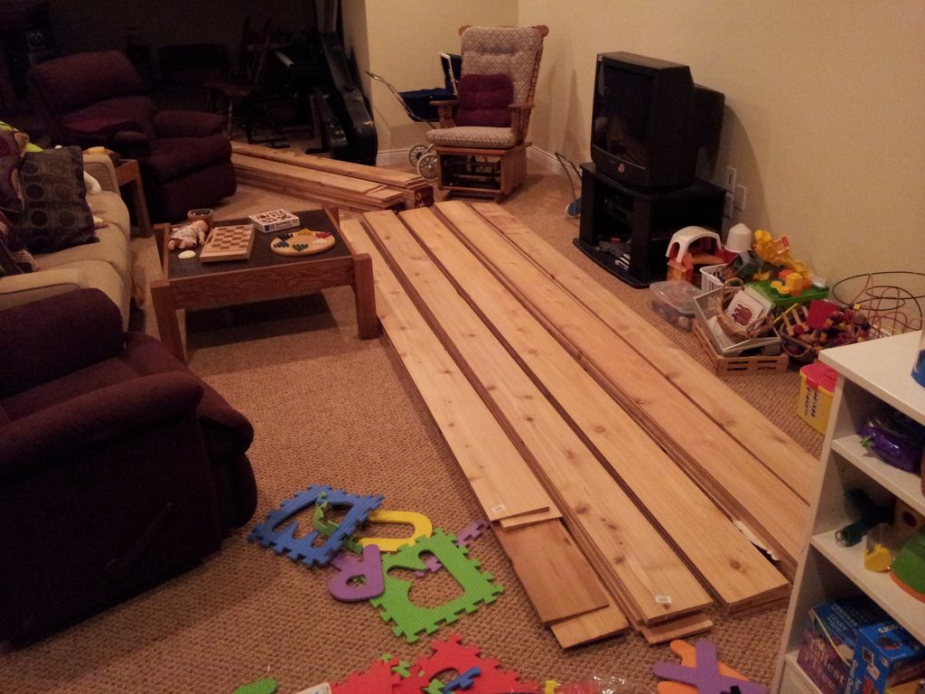
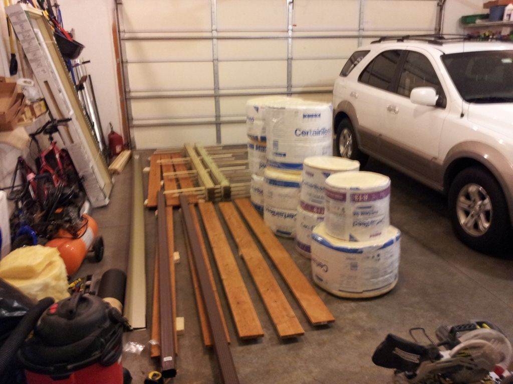
i looked into sauna kits but none of them really seemed to offer everything i wanted. plus i would pay the cost of someone else cutting wood pieces to length, etc. i wanted full control over the materials, sizes, etc. so i opted for the custom option, based on the saunatimes.com concept.

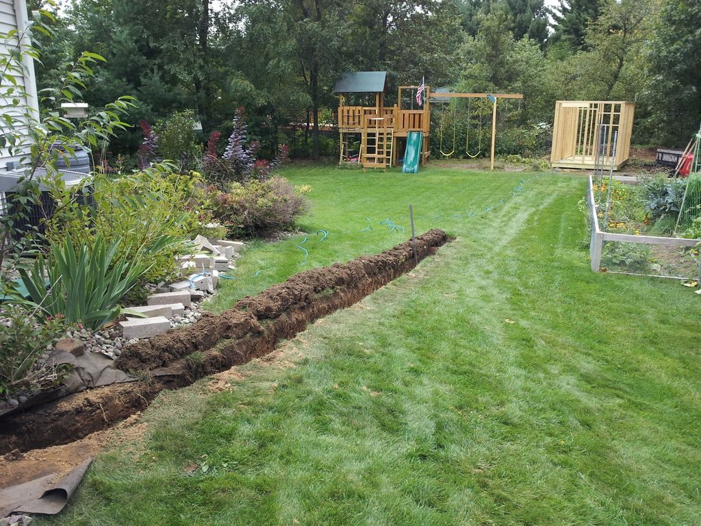
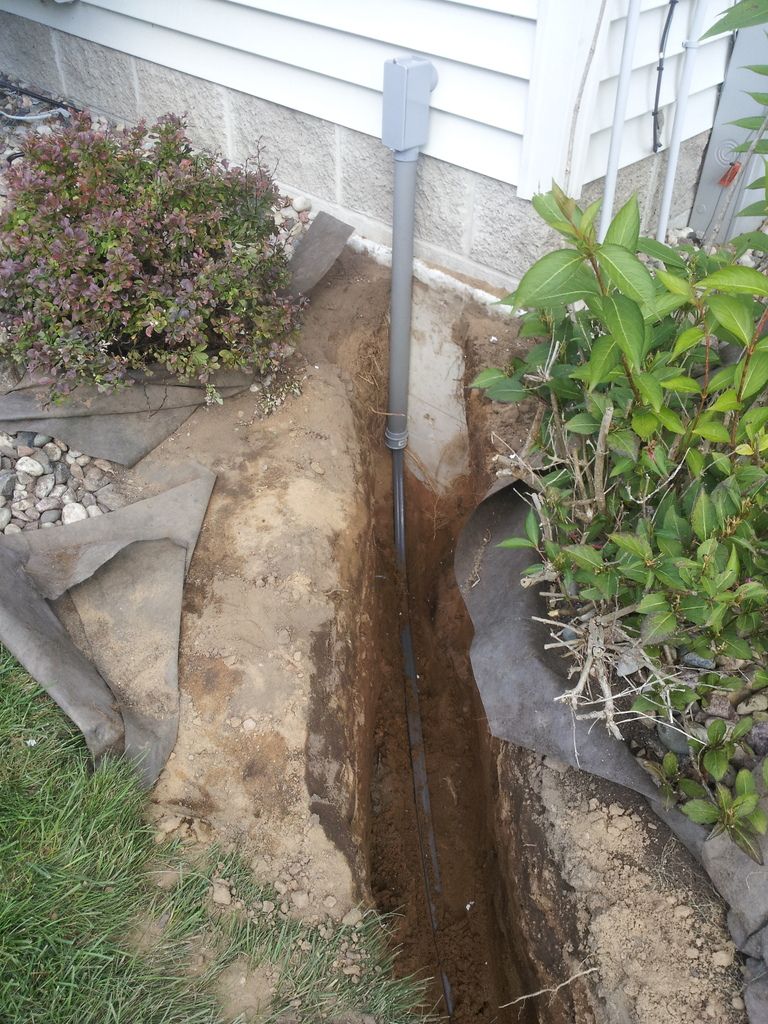
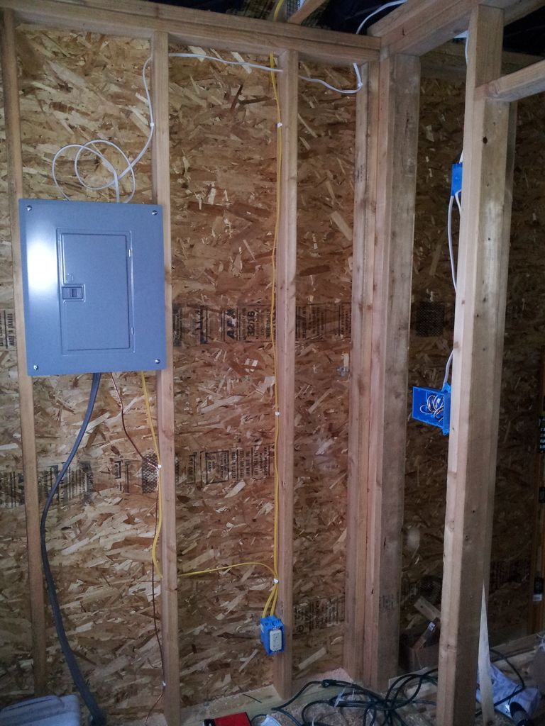
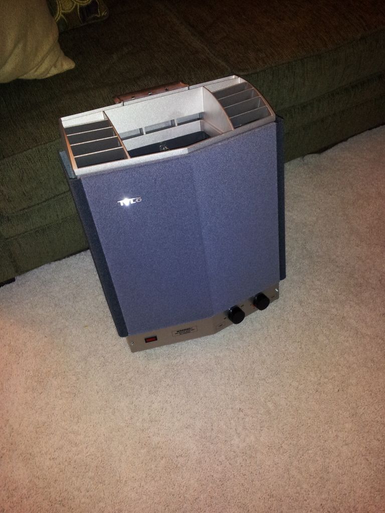
electric vs wood as a heat source was a debate. there is something about that wood heat that adds the extra 'oomph' to the sauna experience compared to electric. i grew up in a home that was heated exclusively with wood so i am no stranger to dealing with wood stoves. on the other hand, our home is in a suburban environment and sourcing wood would be an issue. not a major one but an issue nonetheless, not to forget splitting, storing, etc. i also travel a decent amount for work and didn't want to put my wife in a position where she would have to be fooling around with a wood stove when i am away and she wanted to sauna (she has little wood stove experience and our home has no wood heat). there are also insurance issues with wood heat. so in the end, i opted for the electric sauna and made my plans accordingly.

i also wanted this to be on the up-and-up with the village in terms of permitting. it's one thing to build an indoor homebrew setup on the down-low, it is a completely different animal to build up a structure from scratch in the backyard, lots of opportunity for nosey neighbors or joe q. public to ask what is going on. so i drew up some plans, took them down to the village offices and got a building permit to construct my outdoor backyard sauna.
 
sounds great, did you start yet?

If you want advice from someone who's been living in Finland for 20 years and has built a couple of sauna's, feel free to ask :D
 
08/24/13 update:

our home is on a triangle-shaped lot at the end of a cul-de-sac so the far corner of the backyard is a sort of dead area. this would be the perfect spot to place the sauna. a couple shots of the area, first looking from the house where it will go:

20130824_151407_zpsvsm4xeko.jpg


and a shot from where it will be, looking toward the house. that's the kid's playground off to the right and in the distance, our garden on the left. there is a fire pit in the foreground of the garden:

20130824_151427_zps3ni2rxua.jpg


plan is for an 8'x12' structure, with the 8' side facing the house. i thought about what to do for supporting the structure and opted for 6"x6" treated timbers for a base, with the structure on top. this wasn't the crappy 'not rated for ground contact' treated lumber but the good stuff, the 'structural timbers'. our solil is basically pure sand so i had no qualms not going with footings/piers or a concrete slab or similar. plan was for three 12' 6"x6" timbers, placed such that the top surface is a couple inches off the ground. digging out for the first 'grade beam':

20130824_170153_zpsn4cu111q.jpg
 
08/26/13 update:

digging out the locations for the other grade beams and i have problems:

20130826_182223_zpsah8sfj3v.jpg


that stump was ugly, needed to overdig to get the thing out of there, such a pain in the ass:

20130826_182231_zpscyi8yws8.jpg


a blurry photo but i finally got it out:

20130826_192520_zpswndj1ywz.jpg
 
08/28/13 update:

i backfilled the excavations with clean sand, tamped it and flooded it with water to get good soil compaction. used a 4' level to get everything nice and neat, took some shimming with sand to get it where i wanted it to be. the orange stakes represent the approximate corners of the structure. and damn, those 12' 6"x6" treated timbers were heavy:

20130828_193422_zpsyxiuau7m.jpg
 
all three grade beams installed:

20130901_082336_zpsfolgggrt.jpg


and a higher angle: it may look off but those beams are totally level with each other. wild how surrounding topography and camera angle can make things look out of whack:

20130901_082343_zpsud6xgfcr.jpg


back filled with clean sand. note the 2"x4" on the right beam, to assist in leveling:

20130901_094149_zpsqgfxjnbf.jpg


8'x12' subframe, built from treated 2"x6" lumber:

20130901_110419_zpslz6mpxyw.jpg


floor joists installed, 2"x6" lumber on 16" centers. note the 2"x4" blocking between the joists. this helps stiffen the frame and also provides support for the forthcoming floor insulation. floor insulation is 2" xps foam between the joists and resting on the 2"x4" blocking. blocking is offset to allow for easy end nailing, as opposed to toe nailing everything:

20130901_142605_zpsz5ge56ze.jpg
 
09/03/13 update:

xps subfloor insulation being installed:

20130903_164630_zpsfofozh4t.jpg


subfloor decking being installed. it is 3/4" treated plywood, it isn't going anywhere. before installing decking, i caulked all the xps foam joists to ensure no gaps between foam and joists:

20130903_173207_zpsjlz0zrl5.jpg


sub-floor installed, daughter using the new 'dance floor'. if you think you see an overhang on the floor compared to the sub-framing, you are correct. i purposely made the sub-frame a touch smaller than 8'x12', so the decking will overhang the sub-floor framing. idea is that the building gets 'wider' as it goes up, so raining flowing done it's surface will fall to grade and not pool at the surface below it. and 'wider as it goes up' is a philosophy, not a fast rule. i mean, we aren't building an inverted pyramid here, just trying to minimize pooling water. overhang isn't great, only an 1/8" or so:

20130903_181931_zpsuzvyps5g.jpg
 
ps. it isn't a real digging project unless you hit at least 1 stump or 1 massive rock.... :D

adding some pics of our sauna's for idea's :D

first is our house sauna, basic finnish cellar sauna with shower inside the "hot room"
then 3 of our "cottage sauna" at the saimaa lake.
last ones are my parent's sauna in the Netherlands since they decided to make one after being in finland a few times :D

sauna.jpg


WP_20140606_18_19_22_Pro.jpg


WP_20140606_18_19_30_Pro.jpg


WP_20140606_18_19_49_Pro.jpg


WP_20140728_17_02_17_Pro.jpg


WP_20140728_17_02_26_Pro.jpg
 
posting a lot here :D.
Unless you don't mind running naked through the yard, a dressingroom would be an absolute minimum anyway, wether or not you'd need it for temperature differences. How will you do the "cooling"? are you going to install a shower or small tub style system?

ps. don't tell me it's one of those weird american sauna's where you're not allowed to throw water on the stove....
 
09/09/13 update:

cutting some 2x to length for the walls. walls are built at grade and then tipped up into place. i went with 2x6 walls for the hot room with the smaller 2x4 walls for the changing room and the shared interior wall between the hot room/changing room. i wanted the thicker insulation for the hot room so went with the wider walls. dropping back to a 2x4 makes the changing room a little bit bigger:

20130909_183720_zps90umjkiw.jpg


first few wall sections out on location, bottom plates are treated lumber:

20130909_072114_zpsrzmgsvjz.jpg


and all the sections out there. note the opening for the exterior door on the front wall. heat rises in the sauna so the lower you can keep the ceiling, the less space there is to heat and the closer you get to th ehot stuff at the ceiling. i made my walls just tall enough to accommodate the exterior door with a header. the wall with the exterior door is a gable wall so i technically could have ditched the door header but it just didn't feel right and i didn't want to deal with any potential sagging in the future:

20130909_183807_zpsj2hshzpi.jpg


next step is nailing the walls in place
 
09/11/13 update:

walls in place!:

20130911_072247_zpsla4u7daa.jpg


20130911_072258_zps9hftgdbs.jpg


had a neighbor help hold the walls in place while i nailed them down. not the framing for a window in the shared wall between the hot and changing rooms. it is at head level when sitting on the upper bench in the hot room. idea is to have the exterior door as upper half glass. this way, someone can be in the hot room and still see outside. a window in the hot room directly to the exterior also works but it is a massive heat sink in the winter time. placing it in the shared wall is more energy efficient. plus, looking out the front is the best view for my setup.

starting to look real:

20130911_072320_zpssbqmcgg0.jpg
 
09/21/13 update:

trenching for the electric feeder to the sauna:

20130921_113746_zpshc1u5hed.jpg


it is already late september and i want to make sure i get the electric in the ground before it freezes. i can work on the sauna itself in wintertime but if i don't have any juice out there, what's the point?

i debated using pvc conduit and individual conductors over direct buried cable. the conduit/individual conductors has a lower material cost compared to direct buried plus i only need an 18" deep trench as opposed to 24". but once i factored in the additional effort gluing conduit together and risk of it getting stuck while pulling, i opted to go for direct bury. once past the topsoil, the yard is pure sand. no rocks, no roots, no nothing so digging the extra 6" was no great shakes. in an effort to keep the yard from getting destroyed, i folded over the sod and used a wheelbarrow to cart the sand off to a side area.

the blue cord you see is an extension cord out to the sauna, to measure the length. menards sells uf cable in a 125 ft roll, i need about 110 so it will be perfect.
 
09/24/13 update:

trench dug and cable installed. here is where it enters the house, through an lb fitting and a pvc conduit riser. sauna is served via a 100 amp subpanel i put in when i finished the basement. our house has a 200 amp service with a 42 circuit main panel but 40 of those were used up when we moved in. it was way easier to put in a subpanel than replace regular breakers with tandem panels, work in a hot panel, etc. sub sits right next to the main panel, this is also the sam panel i would later use to serve my electric brewery:

20130924_173228_zpsulc7jcl5.jpg


crossing in-ground sprinkler lines. i had at least three crossings to make and debated simply renting a trencher and chewing right through them, coming back to repair later. i decided to just dig by hand:

20130924_173235_zpsepgsdxcl.jpg


general view of the entire run:

20130924_173241_zpssfngrcmy.jpg


another sprinkler line crossing. this one i did end up dinging with the shovel so had to do a local repair:

20130924_173254_zps3tj3avs4.jpg


at the sauna itself, i transitioned to conduit. my concern was that this is where the walking path would be in winter. depending on how much of the path is exposed would change how deep the frost penetrated. a deep frost penetration at the path could easily reach the buried cable. areas adjacent to the path insulated by snow may not have as deep a frost line, such that it doesn't reach the cable. now the cable crosses an unfrozen/frozen barrier and there is a potential for frost heave and damage to the cable. it is not uncommon for electrical utilities in northern states to require their direct buried cables be in conduit across a driveway or similar exposed surface, to limit potential cable damage due to frost heave:

20130924_173303_zpsffkz6qf3.jpg


and the riser at the sauna, with part of the conduit backfilled to keep it in place. there will eventually be an lb fitting here to penetrate the sauna. also note the extra cable coiled up:

20130924_173313_zpstj8xeulx.jpg


a shot from the sauna looking back toward the house:

20130924_173327_zpsplmim0uu.jpg


my 'spoils piles' from the trench. middle one is topsoil, side ones are sand. this all goes back in the trench after inspection by the village. note a portion of the demon stump remains in the fire pit:

20130924_175820_zpsvochpmw3.jpg
 
10/05/13 update

sheathing time. nothing fancy, your typical 1/2" osb:

20131005_141117_zps9ox2uwlb.jpg


my framing resulted in a couple blind cavities that i would not be able to fill from the inside so i added fiberglass batt insulation while putting up the sheathing. note the 'hurricane clips' on top of the sheathing. this is there to provide propser spacing between panels for expansion/contraction but also work great for holding a piece of sheathing in place while getting that first nail in. a must if doing by yourself:

20131005_141128_zpsyhnfbr1e.jpg


taking shape:

20131005_145654_zpssgbjr1ix.jpg


20131005_162004_zpscor32mcq.jpg


20131005_162034_zpsravuldk0.jpg


and wrapped:

20131005_172400_zpsdbau2dsg.jpg


this is what the view will look like from the top bench in the hot room, through the window between the hot/changing room and the exterior 1/2 lite door:

20131005_172415_zpszqo54olh.jpg
 
10/06/13 update

time to tackle the roof. i opted for some pre-built roof trusses rather than fabricate my own. 2x4 construction, 24" on center:

20131006_134256_zpsjplq0bwf.jpg


view from the interior. the long boards across the top are temporary to hold them in place while i screw them down:

20131006_134306_zpsozmjkcyn.jpg


fly rafters added to the gable ends. i built these myself on the ground, hoisted into place and secured:

20131006_145352_zpsxyltxa6v.jpg


rough fascia and first piece of roof sheathing installed. same deal as the walls, 1/2" osb:

20131006_163545_zpso52sp5ot.jpg
 
10/08/13 update:

roof sheathing complete. amazingly, i got all the sheets up there and nailed down by myself. i needed to get creative with clamps and blocking to make it happen. i also got one piece of drip edge up:

20131008_125847_zpsxkeswdbv.jpg


view from inside. the narrow gap on the left is from the spacing clips, to allow for expansion/contraction. the large gap at the top is for a ridge vent:

20131008_125905_zpsmfuxlndj.jpg
 
10/09/13 update

all drip edge installed, underlayment applied. i used adhesive water and ice barrier for the first row and standard roofing felt for the rest. probably overkill with the water and ice barrier but whatever. starter course of shingles applied, used the roll-style rather than cut individual shingles. stuff reminded me of grip tape for skateboards:

20131009_144840_zpsk4thdhbx.jpg


got a good start on shingling. my father-in-law had some leftover architectural shingles bundles from a project he recently completed, was the perfect amount. i debated buying/renting a coiling nailer to put the shingles on but it is such a small job that i just did it all by hand:

20131009_165754_zpsnwucbssw.jpg
 
10/21/13 update

infamous 11% off sale at menards means time to buy supplies. winter is coming and i wanted to get the exterior stitched up before the weather gets bad. a cart full of cedar siding:

20131021_190852_zps0b2msk23.jpg


i didn't have any real good spot to store the stuff so opted for the basement. sorry, kids:

20131021_223914_zpshnjmjuxl.jpg
 
10/22/13 update

some more ground work before it freezes. i opted to put a subpanel out in the sauna rather than try and just serve the heater directly from the house. heater operates at 240v single phase but i need 120v out there for lights. the nec has rules about remote buildings and the number of circuits that can be pulled to them, a subpanel was about my only option. it is a 12-circuit main-lug-only panel but i only have three local circuits: a 40 amp two-pole breaker for the heater, a 15 amp 120v circuit for lights and a 20 amp 120v circuit for convenience receptacles, one in the changing room and a second on the exterior. i figured i'm going through the effort of getting power out there, might as have an exterior receptacle for tools, a radio, whatever. and i don't need a local main breaker or disconnect since i have less than six breakers in the panel (took me a while to convince the permit office that this was okay).

long intro to the photo but if you put a sub panel at a remote building, you need to re-establish the grounding electrode system. i think it is pointless for this type of structure but code is what code is. to accomplish this, i drove two 1/2" diameter 8' copper-coated steel ground rods six feet apart from each other, nest to the sauna. these were amazingly simple to drive in with our sandy soil. i found a trick online where you make a small starter hole and then using water, pump the rod up and down in the hole until it reaches depth. worked awesome, took one minute to drive each rod and i didn't have to use a hammer or driver or anything. very cool. these get bonded together with #6 bare copper wire and then to the ground bar in the sub panel. the inspector needed to see this before i buried everything:

20131022_163755_zpsseaxeeuv.jpg


more materials. ran out of space in the house so sacrificed a car stall in the garage. the darker wood is 1x6 cedar for trim. also have batt insulation, the exterior door and gutters. also some treated 2x4 for the wall corners, trying to dry them out a little bit:

20131022_202809_zps1bki0brb.jpg


got some more exterior work done. installed the gable-end sheathing and house wrap. also stained the fascia boards and got those nailed in (stained before install, see previous photo). i'm using cedar so opted for the pricier stainless steel nails:

20131022_163826_zpsurpankei.jpg
 
10/26/13 update

gutter and soffit up. note the 1/4" vertical lath on the walls. after researching installation methods, i came across the concept of spacing wood siding off the actual wall. this creats an air gap behind the siding that lets moisture drain away. with a ridge vent, it also creates a 'chimney effect' where air is drawn from below, up the back of the siding and out through the ridge. to this end, the lath was put up and the soffit butted against it to creata a gap for the siding. now downspouts on the gutter yet:

20131026_144009_zpsd7opkxs3.jpg
 
11/03/13 update

siding going up! the incoming electric is in place with an lb fitting but that uf cable is coiled up on the inside of the structure. i stained both sides of the siding in the garage and let it dry. then i cut to length and throw some more stain on the cut end before nailing into place. on the front, you may notice some black material hanging off the bottom of the wall. this is screen material. am installing the siding a 1/4" off the wall so the screen material prevents bugs from crawling up between the siding and sheathing. i put treated 2x4 on the corners to butt the siding against, with plans to cover with 1x6 trim. also note the gutter downspout is installed. i already put that 1x6 trim piece in place behind the downspout:

20131103_154226_zps1ildunw6.jpg
 
11/12/13 update

siding moving along. i debated what siding material to use for a bit but ultimately went with the cedar. i considered vinyl, t1-11, cement board, etc. but ultimately opted for the cedar. it had that rustic look i was going for and would match the cedar on the interior. note all the crap in the interior in the first photo. one nice thing about having the roof on is storing tools, ladders, etc. inside. also note the exterior convenience receptacle in the second photo. it is a 20 amp gfci duplex receptacle with in-use weatherproof cover:

20131112_073202_zpsfae5voop.jpg


20131112_073216_zpsfobmuhtq.jpg


20131112_073232_zpshfhnvr2h.jpg


20131112_073248_zpslkufxgti.jpg
 
11/28/13 update

the snow has arrived. side siding is complete, flashing added for door, corner rough trim in place and started siding the front. constructing in this weather is a pain in the ass. i stain the boards in the garage, let them dry overnight, cut in the garage, stain the cuts and then nail into place. the stainless steel nails are so soft that i actually drilled pilot holes for each nail to prevent bends. and even then i still bent quite a few:

20131128_101422_zpsbyoyxw9m.jpg


20131128_101436_zpszcae7ybr.jpg


20131128_101457_zps9kkt1ku3.jpg
 
11/29/13 update

started interior electrical work. as you walk in the exterior door, the panel is on the left wall, such that it is 'covered' when the door is opened. i don't have any plans for expansion so i went with a flush mounting. at the bottom of the panel, you can see the incoming uf feeder. adjacent to that is the bare grounding electrode conductor connected to the ground rods outside. the yellow cable on the right is the 20 amp circuit for the convenience receptacles. there is one receptacle in the changing room (bottom of photo) and the cable continues up over the changing room to the wall opposite the photo, where it connects to the exterior receptacle.

the white cable coming out the top is a 15 amp circuit for lighting. the two blue boxes on the right are in the shared wall with the hot room (that's the hot room door opening on the far right). the upper box is to serve the light in the hot room. the lower box is a three-gang box in the changing room for the the lights: hot room, changing room and exterior:

20131129_155611_zpscjomdbmg.jpg
 
12/05/13 update

a little more exterior work. i finished off the front facing, up to where i need to start cutting angled siding pieces. also got a mount for the exterior light. i went back and forth on styles and finally opted for a vinyl mount, specifically for beveled siding:

20131205_072733_zpsluwtmmam.jpg


20131205_072743_zps5qo2khty.jpg
 
12/08/13 update

some interior shots, its hard to take decent photos in such a tight space. first is looking through where the hot room door will be, into the changing room. note the house wrap wrapped around the door framing into the interior. the white cable adjacent to it is for the exterior light by the door:

20131208_084743_zpsqgabtkci.jpg


to the left of the photo above:

20131208_084749_zpsmz9ynfqe.jpg


and even further to the left, the side of the changing room. the blue box and yellow cable near the bottom is for the exterior convenience receptacle:

20131208_084804_zpsvnvwcbom.jpg


inside the hot room, insulation starting on the walls. i wanted to drop the hot room ceiling down so installed some 'rafters' below the top plates:

20131208_122431_zpsgibipuvv.jpg


there is a 2x4 on edge along the center of the room. i placed another 2x4 in the horizontal, with the long side flush against the bottom edge of the vertical 2x4. i drilled into the short edge of the vertical 2x4 to counter-sink some screws into the roof trusses above. the horizontal 2x4 is nailed into the vertical spine 2x4. then i screwed 2x4s on the vertical and parallel with the trusses. same deal, countersunk the screws since i didn't have screws that were, like, 6" long that could go through the entire 2x4 and into the one above. then i nailed the ends of the 'rafter's into the 2x6 stud walls. also note the black baffles up against the roof. these maintain a clear air channel against the roof, from the soffit to above the insulation. without this, the ceiling insulation would butt tight up against the roof sheathing and prevent air from transferring up through the soffit and the lathed siding to the ridge vent above. super-critical for a structure like this? maybe not but i'm only doing this once:

20131208_122437_zps9zfmx6ja.jpg


shot from the exterior door into the hot room, best angle i could get. hot room exterior walls and ceiling insulation installed. it was amazing how much warmer that room felt with the insulation up:

20131208_161234_zpsij9umy5c.jpg
 
12/21/13 update

insulation work in the changing room. i used faced insulation in here, with taped seams. i also put in some low voltage boxes and raceway for an audio system with speakers. lower orange box would have a shelf for equipment to sit on and be the location where speaker wire enters the walls. upper box would be one of the speakers in the changing room, near the ceiling. you may also notice the stud for the door opening, looks like it was 'extended' in height. and it was! my original plan was to build my own door between the hot room and changing room and i framed the opening as such. but after some thought, i didn't have enough faith in my woodworking skills to make a door that would be tight and insulated so i opted for a pre-hung cedar sauna door. it has a larger rough opening than i planned so i had to make some modifications to that shared wall between the hot/changing rooms:

20131221_125601_zpsvrjpmcwj.jpg


looking up in the changing room, raceway routed overhead to the opposite side of the changing room, for the other speaker. the two white cables are the lights for the changing room and exterior:

20131221_125609_zpshqwmt2ji.jpg


overhead shot. i secured the raceway periodically so it will be 'stiffer' and easier to pull cables through. the raceway is called 'electrical nonmetallic tubing' (ENT) but is also commonly referred to as 'smurf tube':

20131221_125618_zpsooceptqg.jpg


and the opposite end of the changing room, upper orange box is for a speaker. the ent continues down the wall and terminates. idea here is to have the tubing enter the hot room, below the upper bench. the location on the shared wall will be for an exhaust grill, to help ventilate the hot room:

20131221_125627_zpscoslxfzl.jpg


the 'attic' above the hot room, with all the insulation installed. recall the earlier photo of the lowered ceiling framing installed in the hot room. i used r-11 batts, 3.5" thick by 15" wide, between the lowered 'rafters'. there was a 3.5" gap between the top of the lowered rafters and bottom of the roof trusses, created by the 2x4 on vertical in the middle of the room. so i put another layer of r-11 batts in that cavity, orientated in the opposite direction of the layer below. now the insulation is up to the bottom of the roof trusses. for those, i used r-19 batts, 6.25" thick by 23" wide, between the trusses. these batts are parallel with the lower layer of insulation and perpendicular to the middle layer, helps avoid gaps. so all told, i have an r-41 ceiling in the hot room with r-19 walls and an r-10 floor (from the xps foam board):

20131221_134147_zpsppm6r43d.jpg


all insulation in except the common wall:

20131221_140222_zpshozopogs.jpg


light in the changing room. this is just a cheapo base until the ceiling is finished. stud walls in changing room are 2x4s so i have r-13 faced insulation on the walls, with r-19 faced insulation on the ceiling, between the roof trusses (the changing room does not have a lowered ceiling like in the hot room). also note the exterior light fixture is installed but i don't have a full shot of it:

20131221_140226_zpsx24cibmo.jpg
 
01/07/14 update

happy new year! sauna stove is here. looks like a beauty. i went with the tylo sport 8 kw electric heater. it has a unique feature compared to other electric heaters, 'chimneys' on the sides where the heating element passes through but there are no rocks. rocks are in the center portion only. idea is that while heating, not all the heat goes into the rocks, a good portion heats the air directly, like an element in an electric oven. possibly just a marketing ply but it sounded good to me. i opted for the standard controls, built into the unit (note the temperature and timer dials in the lower right). there are fancier versions out there where the control box is remote from the heating unit but i couldn't justify the extra expense or wiring. there is some cool stuff out there, like the ability to fire up a heater over wifi, set a pre-timer to turn the unit on a half hour before you get home, etc. there are some really cool units available in the european market, real works of art. they are totally safe but many of them don't meet particular aspects of american safety codes so alas, many are not available for retail sale:

20140107_204626_zpsjq71yx0k.jpg
 
01/11/14 update

started insulating the common wall between the hot and changing room. the small 'window' in the wall is for a fresh air intake. idea is to locate it near the heater, so it draws in cool air from below and forces it up into the space. another common approach is to leave a gap under the hot room door. also added blocking for mounting the heater. and note the milkhouse heater. despite the insulation, this is still january in wisconsin and heat is a must:

20140111_135208_zpsywh87t9w.jpg


more of the shared wall between the hot and changing room. the walls really get defined once the insulation is in there:

20140111_135213_zpslr6ag2zt.jpg


a close up of the heater blocking. blocking spaced based upon the mounting bolt locations on the heater. there are also requirements for minimal clearance from side walls, etc. the outlet in the corner is the 40 amp, 240 volt connection for the heater:

20140111_135221_zpsf4sshkbn.jpg


first pieces of vapor barrier going up in the hot room. it is very common to use foil paper, it makes a good seal, is rated for high temp and has reflective properties which help direct heat back into the space. bottom layer goes on first, subsequent layers above will overlap to prevent any moisture from intentionally going into the insulation, sort of like putting up siding:

20140111_140840_zps8pl1qg3t.jpg


more foil work:

20140111_144221_zpscbbi6eay.jpg


first layer complete. the stuff is fairly fragile and susceptible to tearing, needed to take my time:

20140111_144229_zps1o8fc7ds.jpg
 
looking very nice so far.

It seems a lot of american car/electrical regulation is made specifically to keep european brands out of the market....

Too bad, harvia and narvi make the best stoves by a big margin.
 
It seems a lot of american car/electrical regulation is made specifically to keep european brands out of the market....

Too bad, harvia and narvi make the best stoves by a big margin.

i believe most of it has to do with listing agencies. some european equipment is built to standards/testing that isn't recognized here in the states. the equipment would likely pass the american standards/tests but would require the manufacturer to pay for the analysis, tests, etc. i suspect for many manufacturers that the costs just aren't worth it.

there are cheaper heaters out there than the tylo but i really liked the features of it and it is made in sweden.
 
01/12/14 update

more foil work, starting on the second layer:

20140112_112551_zpsmrzh9wo8.jpg


around the window. a little hard to see in the photo but i am using foil tape at the seems to keep everything tight:

20140112_112558_zpsszgdsjhn.jpg


from the changing room, looking in. not the faced insulation on the changing room side of the common wall, more on that later:

20140112_112611_zpsinefnpf3.jpg


top layer of the walls complete, moving on to the ceiling:

20140112_125946_zpsl1kfaqu3.jpg


small openings in the common wall for the electrical and vent:

20140112_125959_zpsotm5dtag.jpg


more ceiling work. note the left side, i had issues with the insulation sagging and causing problems getting the foil up so i used some tape to hold it in place:

20140112_130008_zpsqlvk0qsh.jpg


almost there. foil is held in place with staples:

20140112_135908_zpsb5wqtv3y.jpg


last piece:

20140112_135915_zpsuec9dusn.jpg


done! finally, some protection from those mind-reading satellites:

20140112_135933_zps9wfjn8oz.jpg
 

Latest posts

Back
Top