
Please forgive me if this has been created/posted somewhere else. I believe my research skills are adequate and I couldn't find a place that had this build in one spot, so I decided to share what I've found. This was an absolute pain to build (mainly due to my own shortcomings) but I am ultimately happy with what I put together.
DISCLAIMERS: I do not take credit in any way for what I'm sharing; I have merely pieced together what I could find that was posted, created, and built by others.
Working with electricity is involved so take precautions or don't attempt if you aren't comfortable.
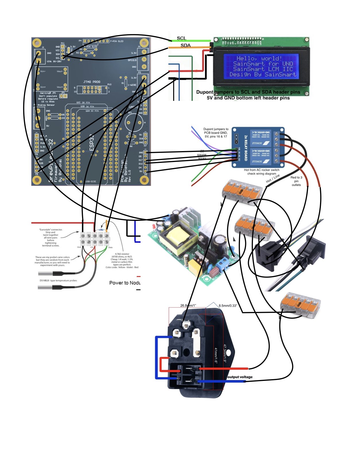
Please forgive my poor wiring diagram! I pieced together other diagrams created by other people - those links will be shared.
Websites sourced:
https://github.com/vitotai/BrewPiLess - the whole reason we are here today!
BrewPiLess esp8266 build - this site was my main source of information and was visited too many times to count.
https://thehoppyvalley.com - source code upload information, if you want to go the VScode with Platformio route.
https://github.com/stefschin/BrewPiLess-32-PCB - download the zip files and take them to your PCB website of choice. Two of the ones I liked best are listed below.
https://www.brewflasher.com - the easiest and simplest way of getting your esp32 flashed.
Materials list (BoM) - these are links to the materials I used, but there are a plethora of other options:
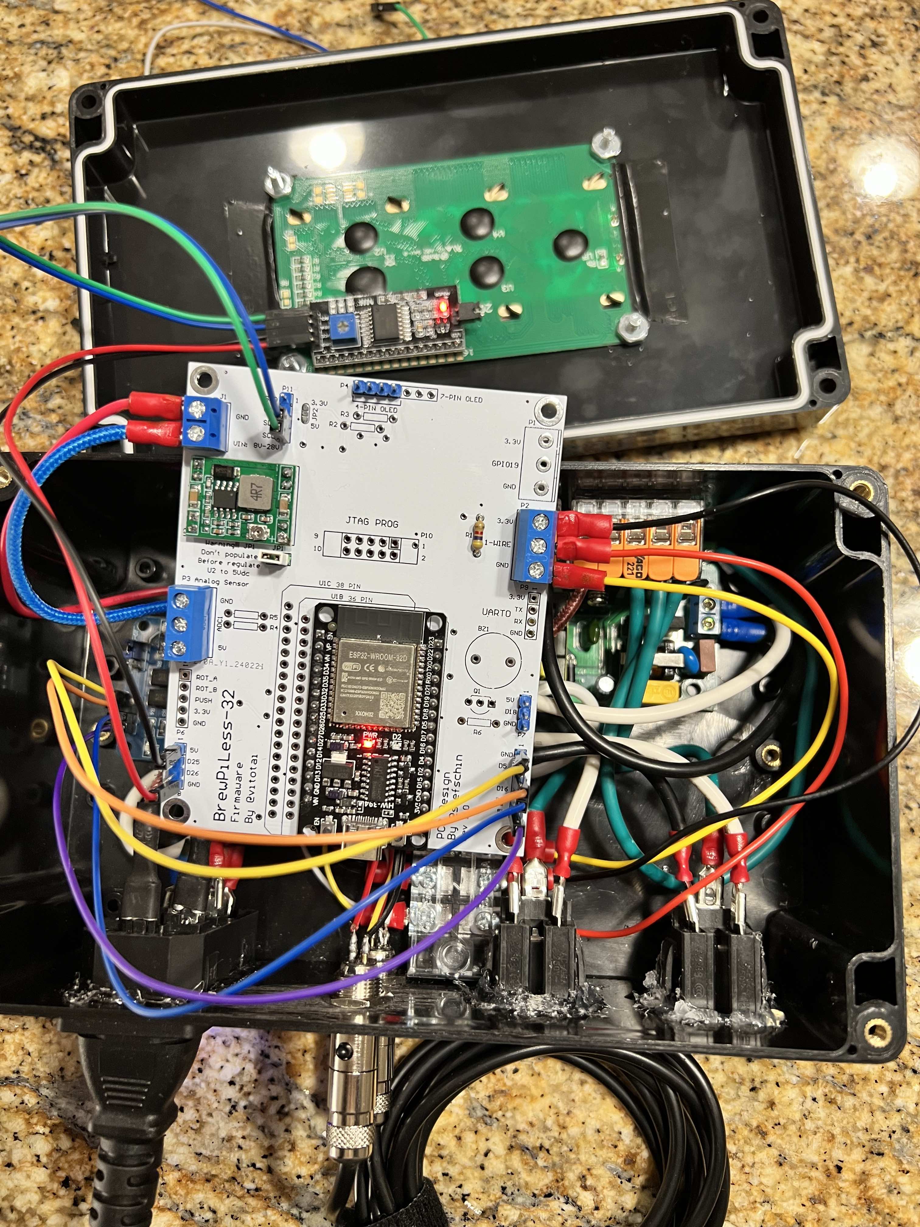
PCB boards aren't necessarily required, but make the project that much easier and "cleaner". I briefly looked into esp32 breakout boards, but had mine about 85% completed so I don't have much information to be offered about them. https://jlcpcb.com and https://www.pcbway.com are some options to get yours made.
esp32 development boards
2 channel relay
DS18B20 temperature probes
2 and 3 pin screw terminals
3 pin mini xlr connectors male and female (these are a pain in the rear to solder)
Dupont jumper cables
3 pin AC rocker plug with 4 pin lighted switch - please use a 10A fuse instead of the included 5A
20x4 LCD display
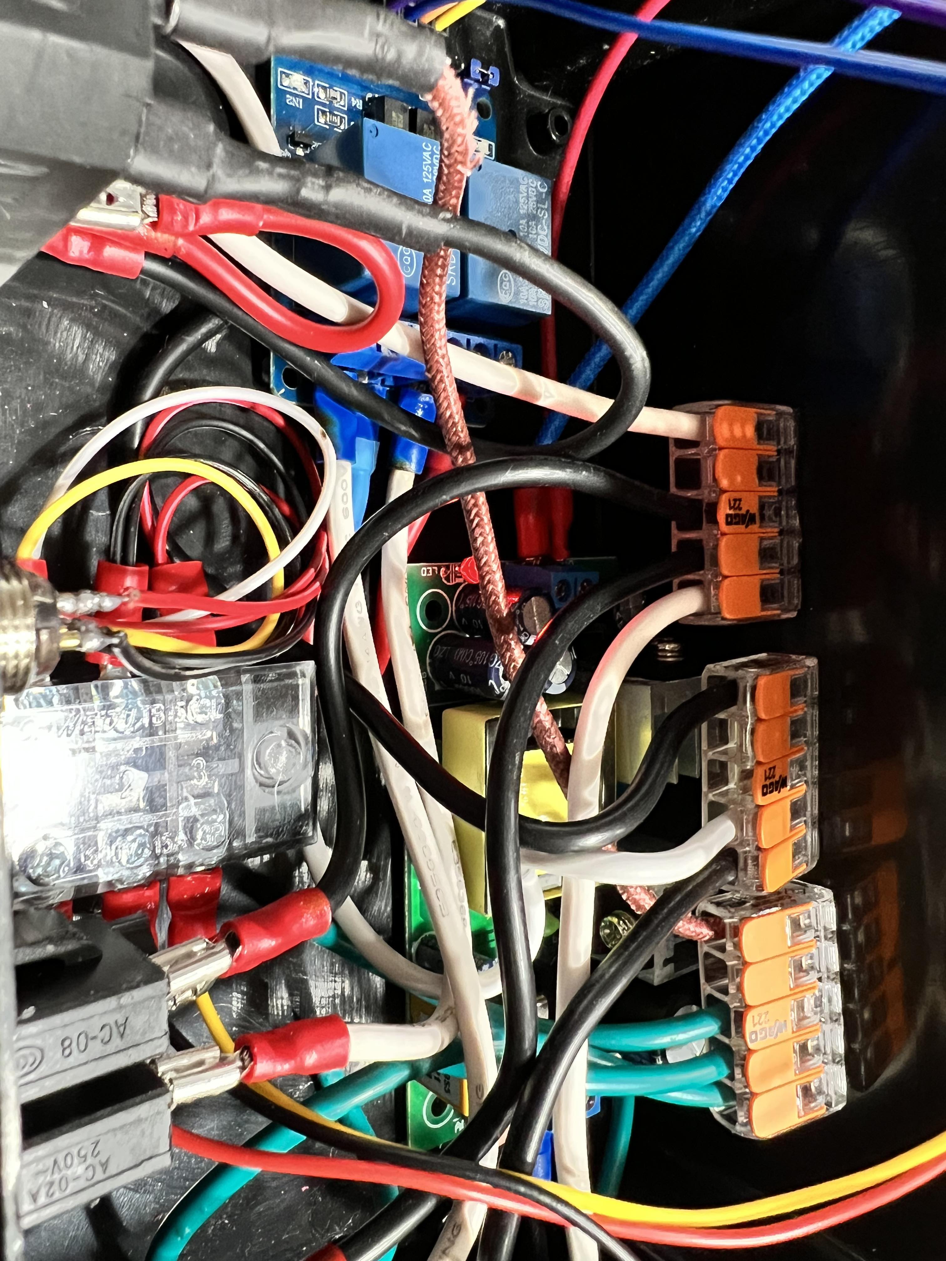
Junction/project box 7.87” x4.72” x2.95” - I have a birds nest of wires, so my recommendation is to get a bigger box.
3 position block for 1-wire connections (not the same thing as the screw terminals for the PCB board)
Power Supply Module AC 120V 100V-264V to 5V 3A 3000mA 15W Isolated Step-Down DC Module (5V 3A)
Ultra Small DC-DC 3A Power Step-Down Adjustable Module Buck Converter 24V to 12v 9V 5V 3V
4.7k ohm resistors
breakable straight header pins for PCB board
10 pin male header box socket for JTAG
jumper cap for headers
500w mini space heater or reptile heat pad/tape - you will pay almost double if you search for Fermwrap
18AWG 10' power cable or can get here Lowe's power cord
Panel Mount Outlet Power Socket Plug 3 Pins AC 15A 125V (US)
lever wire nut
spade quick disconnects but I recommend spade connects with sleeves
Not linked:
assorted size wire 22g - 14g (needed)
double sided tape (optional)
soldering kit (needed)
digital multimeter (needed)
Notes:
The LCD display has a gray "dial" that will fit a small phillips head screwdriver. This is to change the intensity of the screen because you may think its not working when it is. Adjust this as a first troubleshoot.
The Ultra small DC-DC step-down converter also has a phillips head spot on it in order to regulate the voltage going to the board. You will need to use a multimeter to make sure you are getting the right voltage, or you could damage components. If you look at the PCB build, you will notice it says, "Warning JP1, don't populate before regulate U2 to 5vdc" This means to turn the screw until you meter shows the correct voltage. Once regulated you can add the 2-pin jumper cap and you board will receive power. For me, in order for the LCD to work, I had to regulate to 8vdc.
The 4.7k ohm resistor can be mounted to the PCB board or added between the voltage and data wire going to the board as seen in the wiring diagram.
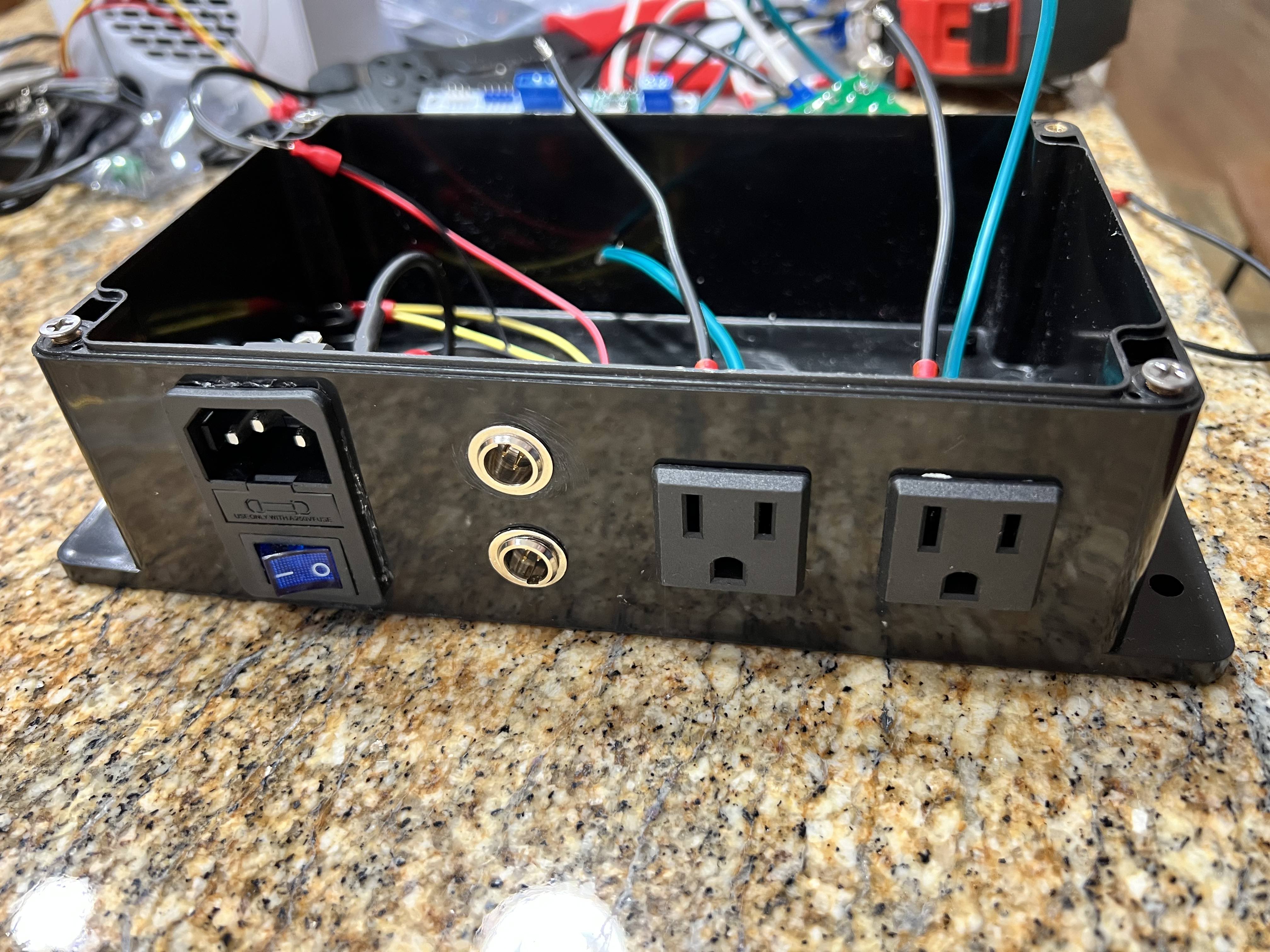
Make sure to rotate your panel mount power sockets with the ground pin facing the front/top of the box if you plan to mount it vertically. I mounted my project box to the face of my freezer and had to remove, rotate, re-glue one of the sockets to fit in the three-prong freezer plug.
DISCLAIMERS: I do not take credit in any way for what I'm sharing; I have merely pieced together what I could find that was posted, created, and built by others.
Working with electricity is involved so take precautions or don't attempt if you aren't comfortable.
Please forgive my poor wiring diagram! I pieced together other diagrams created by other people - those links will be shared.
Websites sourced:
https://github.com/vitotai/BrewPiLess - the whole reason we are here today!
BrewPiLess esp8266 build - this site was my main source of information and was visited too many times to count.
https://thehoppyvalley.com - source code upload information, if you want to go the VScode with Platformio route.
https://github.com/stefschin/BrewPiLess-32-PCB - download the zip files and take them to your PCB website of choice. Two of the ones I liked best are listed below.
https://www.brewflasher.com - the easiest and simplest way of getting your esp32 flashed.
Materials list (BoM) - these are links to the materials I used, but there are a plethora of other options:
PCB boards aren't necessarily required, but make the project that much easier and "cleaner". I briefly looked into esp32 breakout boards, but had mine about 85% completed so I don't have much information to be offered about them. https://jlcpcb.com and https://www.pcbway.com are some options to get yours made.
esp32 development boards
2 channel relay
DS18B20 temperature probes
2 and 3 pin screw terminals
3 pin mini xlr connectors male and female (these are a pain in the rear to solder)
Dupont jumper cables
3 pin AC rocker plug with 4 pin lighted switch - please use a 10A fuse instead of the included 5A
20x4 LCD display
Junction/project box 7.87” x4.72” x2.95” - I have a birds nest of wires, so my recommendation is to get a bigger box.
3 position block for 1-wire connections (not the same thing as the screw terminals for the PCB board)
Power Supply Module AC 120V 100V-264V to 5V 3A 3000mA 15W Isolated Step-Down DC Module (5V 3A)
Ultra Small DC-DC 3A Power Step-Down Adjustable Module Buck Converter 24V to 12v 9V 5V 3V
4.7k ohm resistors
breakable straight header pins for PCB board
10 pin male header box socket for JTAG
jumper cap for headers
500w mini space heater or reptile heat pad/tape - you will pay almost double if you search for Fermwrap
18AWG 10' power cable or can get here Lowe's power cord
Panel Mount Outlet Power Socket Plug 3 Pins AC 15A 125V (US)
lever wire nut
spade quick disconnects but I recommend spade connects with sleeves
Not linked:
assorted size wire 22g - 14g (needed)
double sided tape (optional)
soldering kit (needed)
digital multimeter (needed)
Notes:
The LCD display has a gray "dial" that will fit a small phillips head screwdriver. This is to change the intensity of the screen because you may think its not working when it is. Adjust this as a first troubleshoot.
The Ultra small DC-DC step-down converter also has a phillips head spot on it in order to regulate the voltage going to the board. You will need to use a multimeter to make sure you are getting the right voltage, or you could damage components. If you look at the PCB build, you will notice it says, "Warning JP1, don't populate before regulate U2 to 5vdc" This means to turn the screw until you meter shows the correct voltage. Once regulated you can add the 2-pin jumper cap and you board will receive power. For me, in order for the LCD to work, I had to regulate to 8vdc.
The 4.7k ohm resistor can be mounted to the PCB board or added between the voltage and data wire going to the board as seen in the wiring diagram.
Make sure to rotate your panel mount power sockets with the ground pin facing the front/top of the box if you plan to mount it vertically. I mounted my project box to the face of my freezer and had to remove, rotate, re-glue one of the sockets to fit in the three-prong freezer plug.
Attachments

Last edited:
