YABC-Yet a Brew Controller: BrewManiacEx

Homebrew Talk - Beer, Wine, Mead, & Cider Brewing Discussion Forum

Help Support Homebrew Talk - Beer, Wine, Mead, & Cider Brewing Discussion Forum:

This site may earn a commission from merchant affiliate links, including eBay, Amazon, and others.
No. That isn't it. The window size can't be 2ms. You must use PWM function of ESP8266.

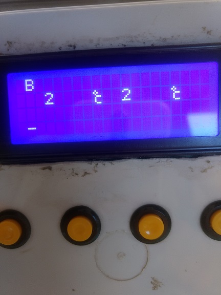
Your description seems to be disagree with your pic. I don't really get it.
Assuming the period is 2m, and 100% cycle means full open while 0% means close.(Will the fire be lit when it opens again?)

Then you will need to initialize the PWM PIN,( you can use D7).

analogWriteRange(500); // 2 microseconds, 500hz

Then, you call the following function to set duty cycle.

analogWrite(D7, (pidOutput/255) *1023);


This is the rough idea.


Man you make it look easy.. It would be interesting that the output could drive a servo, that way you could mechanically actuate something proportionally.

And yes for gas, you would always have a pilot flame on.
 
Would you share the information of the valve? I am interested in building a gas fired coffee roaster.
 
Would you share the information of the valve? I am interested in building a gas fired coffee roaster.

Well I´ve never done anything like it, but it can easily be done as this.


For setting the output pin in the esp8266 as PWM, do I set it in pin config inside the bin file, by editing it in platformio?


I suck at this.
 

Attachments

  • maxresdefault[1].jpg
    maxresdefault[1].jpg
    60.5 KB · Views: 78
Well I´ve never done anything like it, but it can easily be done as this.


For setting the output pin in the esp8266 as PWM, do I set it in pin config inside the bin file, by editing it in platformio?


I suck at this.


I though ball valve isn’t good at regulation of flow and gas is usually controlled by needle valve.

You have to modify the code and build image in platformio. It’s easy. The difficult part is the hardware build/setup.
 
I though ball valve isn’t good at regulation of flow and gas is usually controlled by needle valve.

You have to modify the code and build image in platformio. It’s easy. The difficult part is the hardware build/setup.

Well a ball valve is one option it might not be strictly proportional but it's better than on off.

Another one is to use old gas burners and recycle their valves. I might even find them lying around thrown away.

An electric proportional valve would be top notch but economically unviable.
 
Well a ball valve is one option it might not be strictly proportional but it's better than on off.

Another one is to use old gas burners and recycle their valves. I might even find them lying around thrown away.

An electric proportional valve would be top notch but economically unviable.

How about reliability?
Risk might turn to cost.
 
How about reliability?
Risk might turn to cost.

I don't think reliability would be an issue. Where I live we use gas burners for everything since gas is cheaper than electricity. All valves are daily used. For cooking or whatever.

Servos are also very durable. And also have many lying around from plane models.
 
Hi all and especially Vito,
super interesting project for my single vessel brewing system (my is based on old table plate stove heater, old brewering pot, magnetic brewing pump and 21L plastic bucket fermenter)!

Question,
is it correct understod if I buy the "BrewManiacEx BrewShield" I only need the following part list (excluding the need of sparge heating):
1. Wemos D1 mini $5
2. I2C 20x4 LCD. $5-8
4a. membrane keypad $2
4b. Might need an extension cord for this one?
5. buzzer. $1
6. Ds18B20 waterproof sensor $2-3
8. 2x SSR w/ heat sink $6-8

Salvage somewhere:
9. 5V power supply $5 (could be any Iphone/Ipad 2A USB adaptor)
10. waterproof case $15-18 The most expensive one!
11. sockets, power cord $5-

And secondly, the need for soldering is gone (did the Ispindel project, and that was a killer for me :)

The current setup can be seen here (using solar pump, but do not reccomend this one as it give metallic taste off. Control with my STC1000 drawing 7A (220v and 1800W plate). Updated setup dosent use cupper tube nor brass connectors as to remove all risk of metallic taste:
https://1drv.ms/v/s!An5QQQ1io7W7h_9yy6q8zPLMBZgJDg

Klaus of Denmark (sounds so majestic :)
 
Last edited:
To control heating, you MUST NOT use mechanical relays because PID algorithm switches heating element fast. Mechanical relays switch slowly, and fast switching will kill them.

To control PUMP, you MIGHT use SSR or mechanical relay. However, if you use DC pump, SSR with zero crossing will NOT work. It seems that a lot of SSR are zero crossing switching.

The Sonoff won’t work. First, it uses mechanical relays. Second, it has only 1M bytes flash, which is not enough.
 
So..

I´ve come with some tests done.

Apparently the servo doesn’t work properly when using the pwm output directly from the mcu.

On the other hand I do get a PWM signal out of it because I can measure a proportional voltage coming out of it. This proportional value changes when temperature gets further away from the temperature setting.


I´ll interface the MCU with an Arduino nano with the servo.h library so I can control the servo better using the PWM output from the mcu, obviously previously filtered to get a more average value.


Web interface does not work properly. I can command the buttons but that’s it. All temperature values shown are wrong or stuck, and also web interface shows error! sign on top. That sucks.


When I get something else i´ll post it.
 
Hi there,
still looking at this project for a brew controller! But as i wish to go headless I would like to know if anyone have tried this, eg. running it without LCD+keypad and buzzer?

Second question, can the pump be controlled by pwn, eg. my 40W pump is powerfull and wish to run it at 25% and questiosn it then if pump can be set at a given level in the BrewManiacEx?

KBN
 
BrewManiacEx isn’t designed to run headless. You might not know the exact status and perform some operation without buttons and LCD.
 
@pocketmon , what do I need so I may swap the LCD 2004 for an oled 128x64 one? Build the firmware with any modifications? I got this oled here, and no 2004 on hand. Thanks!
 
Last edited:
Oh, and by the way - anybody who uses my PCB design, please let me know if there is any bugs you have found. Everything works fine for me - but i may have missed something, since there is a possibility of different setups.
Thank you for your sharing. but it is impossible to download the files.
Could you share it on EASYEDA website?
i am going to test it.
 
Yes. You have to change the configuration and rebuild.
change the line
https://github.com/vitotai/BrewMani...686a6164df4b5a9627182439a2da/src/config.h#L48

to

Code:
#define LCD_USE_SSD1306 true

Hey, thanks for the answer.
But I am getting a bunch of this (invalid conversion), trying to build with no changes:
Code:
Compiling .pioenvs/nodemcuv2/lib4e7/ESPAsyncTCP-master/SyncClient.cpp.o
lib/ESPAsyncTCP-master/src/ESPAsyncTCP.cpp: In constructor 'AsyncClient::AsyncClient(tcp_pcb*)':
Compiling .pioenvs/nodemcuv2/lib259/Hash/Hash.cpp.o
lib/ESPAsyncTCP-master/src/ESPAsyncTCP.cpp:71:28: error: invalid conversion from 'int8_t (*)(void*, tcp_pcb*, pbuf*, int8_t) {aka signed char (*)(void*, tcp_pcb*, pbuf*, signed char)}' to 'tcp_recv_fn {aka long int (*)(void*, tcp_pcb*, pbuf*, long int)}' [-fpermissive]
tcp_recv(_pcb, &_s_recv);
^

Maybe a problem with that lib? I will try to update it...
Never used VSCode nor Platformio.

Short answer:
use this branch:
https://github.com/vitotai/BrewManiacEsp8266/tree/v040pre

Or, you can force PlatformIO to use 1.5 framework by modifying the platformio.ini
platform = espressif8266@~1.5
 
Thank you for your sharing. but it is impossible to download the files.
Could you share it on EASYEDA website?
i am going to test it.

It is very easy to download, this is a regular link to a google drive directory. When you enter the link, you'll see files/folder in the center - but at the top above (still inside browser window) there is a "menu bar". And far to the right on the menu bar, there are a few "buttons" or whatever you call them. The button with an arrow pointing downwards is the download button. :)
 
Hi Vito - Just looking at your new 0.4.2 - regarding the mash level sensors - can you explain the logic to me//the way you envisaged the process working?

The Pin allocation is this via dallas 1-wire or via I/O pinout on the ESP8266? If you were going to implement it via the brewshield how would you do that?

Just trying to get my head around it before trying to implement it.

When the level sensor is triggered, the Pump and heating will be stop/paused/suspended or put into REST. The REST state will be extended for a configurable time after the "full" signal cleared. There is also one additional setting of minimum triggering time to avoid false alarm. You can find some illustration on my blog.

Unfortunately, I didn't think of this when designing BrewShield. There is no free pins available but the additional actuator controlling PINs. I haven't tested it and will report back.
 
Hi again guys,

I´m with an issue. I´ve been tinkering with my brewmaniacex d1 mini, and somehow now i´ve got an issue with the screen display as shown below.

I tried another lcd screen and it´s not it. Also there is no way i can acces the bm.local page trough wifi.
I´ve checked connections and they are all fine. Everything works as expected, except the screen. I can surf trough menus and stuff, i can see they change accordingly to what buttons i press, i can turn on and off the heater and pump, but the lcd is unreadable, only a few characters are shown.

Wifi is working but somehow I cannot acces it, not with my phone or laptop..

Is there a way I can reset my wemos d1 board?? or load an older version of brewmaniac so that wifi AP works?

As you can see in the picture, only the first characters are shown.... but it unuseable...
 

Attachments

  • IMG_20180909_172747789.jpg
    IMG_20180909_172747789.jpg
    1 MB · Views: 159
Well.. I got it to work as before. Apparently the "I don't know how it's called" espressiff 8266 version 1.8.0 doesntd work well.

Used the previous one and it worked.

What still doesntdwodoe is WiFi access or actually wifi anything. I'm running version 4.2 of bmex.
 
Everything fixed. Got it working with version 4.2. iI' using a gas water heater burner. It says 20000kcal. So it might be good. I'll post the Brew log in some minutes.

kmnCNxD.png


Also i´ll upload a video of how the gas burner is working. It´s actually working very good..

The only thing i´m worrying now is that maybe the cooling down is´nt very fast. Took 25minutes to go from 95Cº to 23Cº. Tap water was used (at 19.5Cº) in an immersion chiller. The immersion chiller was maybe a third covvered by water. Full volume was about 20 liters. (only water no brewing this time)
 
Last edited:
Everything fixed. Got it working with version 4.2. iI' using a gas water heater burner. It says 20000kcal. So it might be good. I'll post the Brew log in some minutes.

kmnCNxD.png


Also i´ll upload a video of how the gas burner is working. It´s actually working very good..

The only thing i´m worrying now is that maybe the cooling down is´nt very fast. Took 25minutes to go from 95Cº to 23Cº. Tap water was used (at 19.5Cº) in an immersion chiller. The immersion chiller was maybe a third covvered by water. Full volume was about 20 liters. (only water no brewing this time)

I just check in v0.4.3 while 0.4.2 doesn’t work with 0.4.3 HTML/JS.

How do you fix the LCD issue?
 
Apparently the lcd thing was a flashing issue. I uninstalled the 1.8.0 version of the "i dont know what it is" of the esp8266. I used the older one 1.5.0 to flash everything again.

0.4.2 has a non working html/js?
 
Apparently the lcd thing was a flashing issue. I uninstalled the 1.8.0 version of the "i dont know what it is" of the esp8266. I used the older one 1.5.0 to flash everything again.

0.4.2 has a non working html/js?

0.4.2 firmware might not work with 0.4.3 HTML/Javascript because 0.4.3 doesn't have a version.txt that 0.4.2 firmware uses to check version of HTML/Javascript.

I am guessing something about I2C library changed in 1.8.0. will dig into it. Thank you.
 
0.4.2 firmware might not work with 0.4.3 HTML/Javascript because 0.4.3 doesn't have a version.txt that 0.4.2 firmware uses to check version of HTML/Javascript.

I am guessing something about I2C library changed in 1.8.0. will dig into it. Thank you.
Well mine is working fine since I had to manually upload the html-js version 0.4.2 files in order to work, otherwise it would show the older version which i had installed (0.3).

I have´nt tried updating OTA after all this manual tinkering I´ve done.
 
If you are using gas i can tell you how to mod one of these..

images


EDIT:


This is a video to show how it works.


Modificaion.

You need to modify the diaphragm in the shown way. Grooves through the diaphragm should be cut, in order to bypass the original tiny holes that pilot the valve when it works with water.

This grooves will communicate the inlet chamber and the pilot chamber direclty. This way we bypass the diaphragms working action.
Now the piston will be the only element allowing the gas passage.

You have to enlarge the hole in the plastic core (the one attached to the diaphragm), in a way that it is large enough for the gas flow needed, and small enough that the pistons head can cover it.

valve.jpg


You might want to use an inlet valve that has the biggest possible walls around the hole, so that you dont run out of plastic when enlarging it.

Thats reaaly all of it. The problem you might encounter is tat after drlling the hole, the upper rim of the hole, where the pistons head seats,now fails to close perfectly.

I fixed that by placing or making a small silicone deposit, and then matching up the head with the silicone so that a seat forms. To avoide the head of the piston sitcking to the "yet to cure seat" I used a drop of detergent on the piston.

Let sit overnight, assemble everything and test. Check for the newly mad eseat to work propperly. Check for gas leakes when the solenoid is not energized. If some gass passes, then it should be reworked.
 
Last edited:
Yes I did. What does that do? The window set function? Should it be even longer?
Let's take 5 and 20 seconds for example.
If the required output is 50%, then the heating will be on for 2.5 seconds and 10 seconds, repeatedly.
If output is 10%, they will be 0.5 seconds and 2 seconds.

I think 0.5 or even 2.5 seconds is too short for gas.
 
Let's take 5 and 20 seconds for example.
If the required output is 50%, then the heating will be on for 2.5 seconds and 10 seconds, repeatedly.
If output is 10%, they will be 0.5 seconds and 2 seconds.

I think 0.5 or even 2.5 seconds is too short for gas.
Oh no way. I'm totally changing that on my ardbir system for short bursts. I didn't know that's what that did
 
In Ardbir, the windowSet value is fixed to 40 seconds if gas option is selected.
That makes sense. My system is electric and I boil at around 80% the window is default and it's slow I just didn't realize that could be changed
 
Let's take 5 and 20 seconds for example.
If the required output is 50%, then the heating will be on for 2.5 seconds and 10 seconds, repeatedly.
If output is 10%, they will be 0.5 seconds and 2 seconds.

I think 0.5 or even 2.5 seconds is too short for gas.

Alright. The thing is I have to wait 40 seconds for the duty cycle to refresh. No problem with that since brewing 50l will have plenty of thermal Inertia to absorb more heat.

Is there a way to avoid the relay reset/update everytime the window set cycles? I hasn't happened again but once it made my lcd screen go crazy. It's the EMI.
 
Back
Top