Hi All,
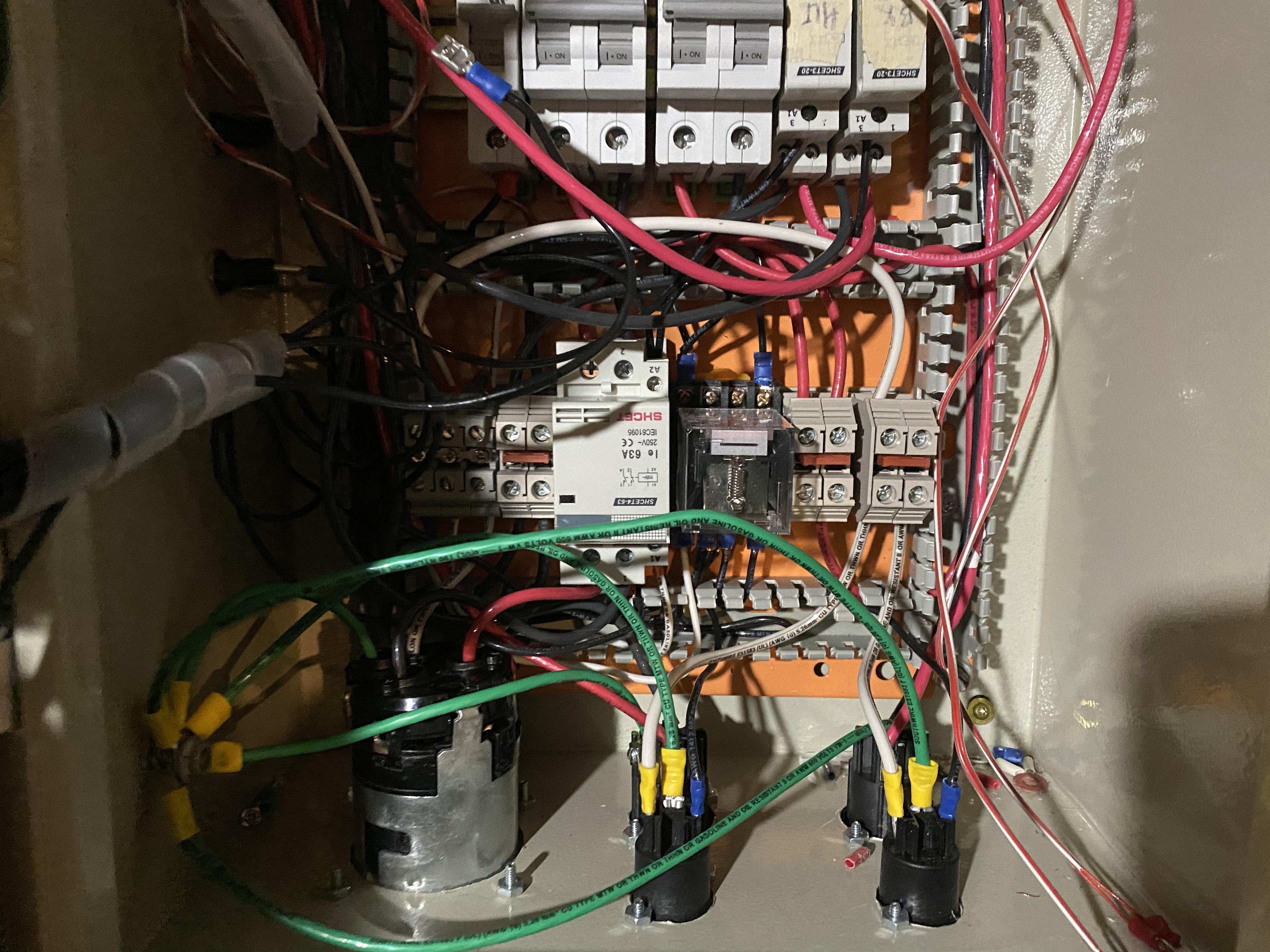
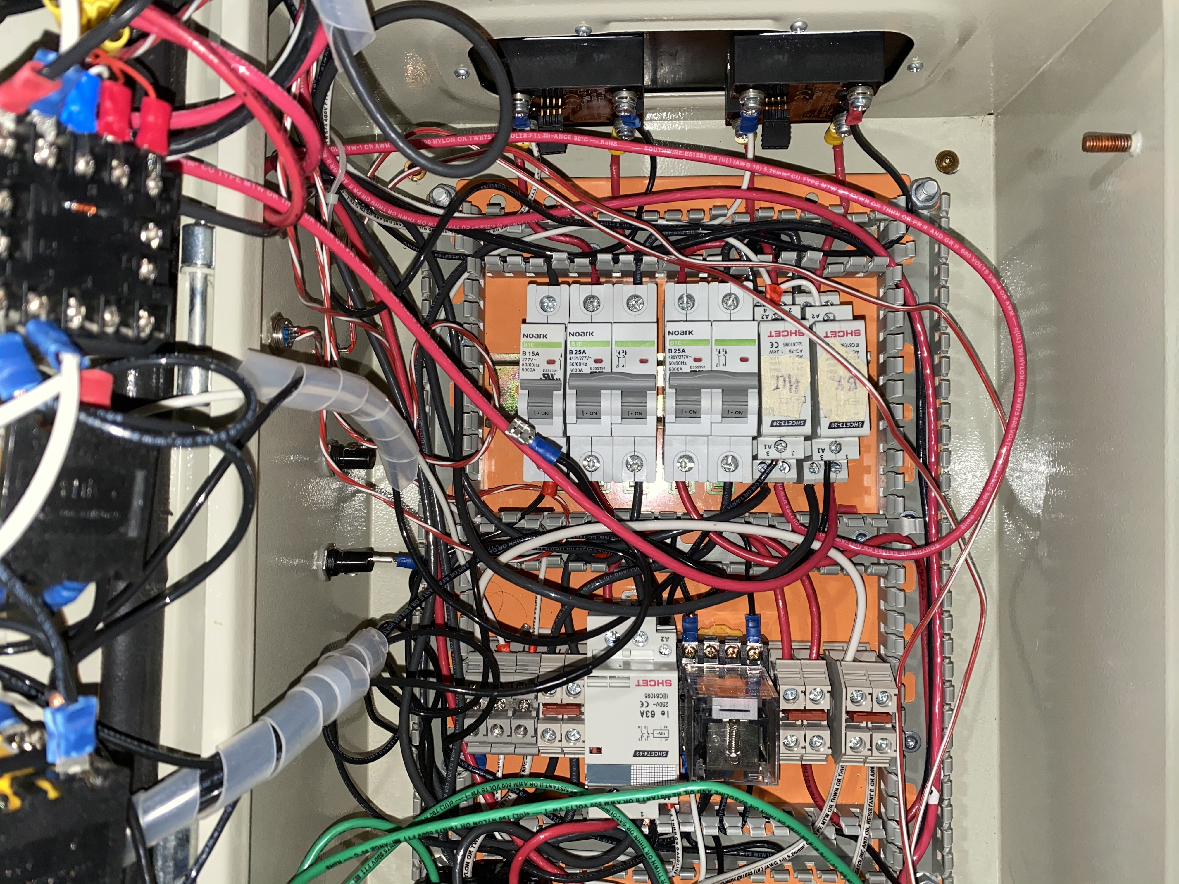
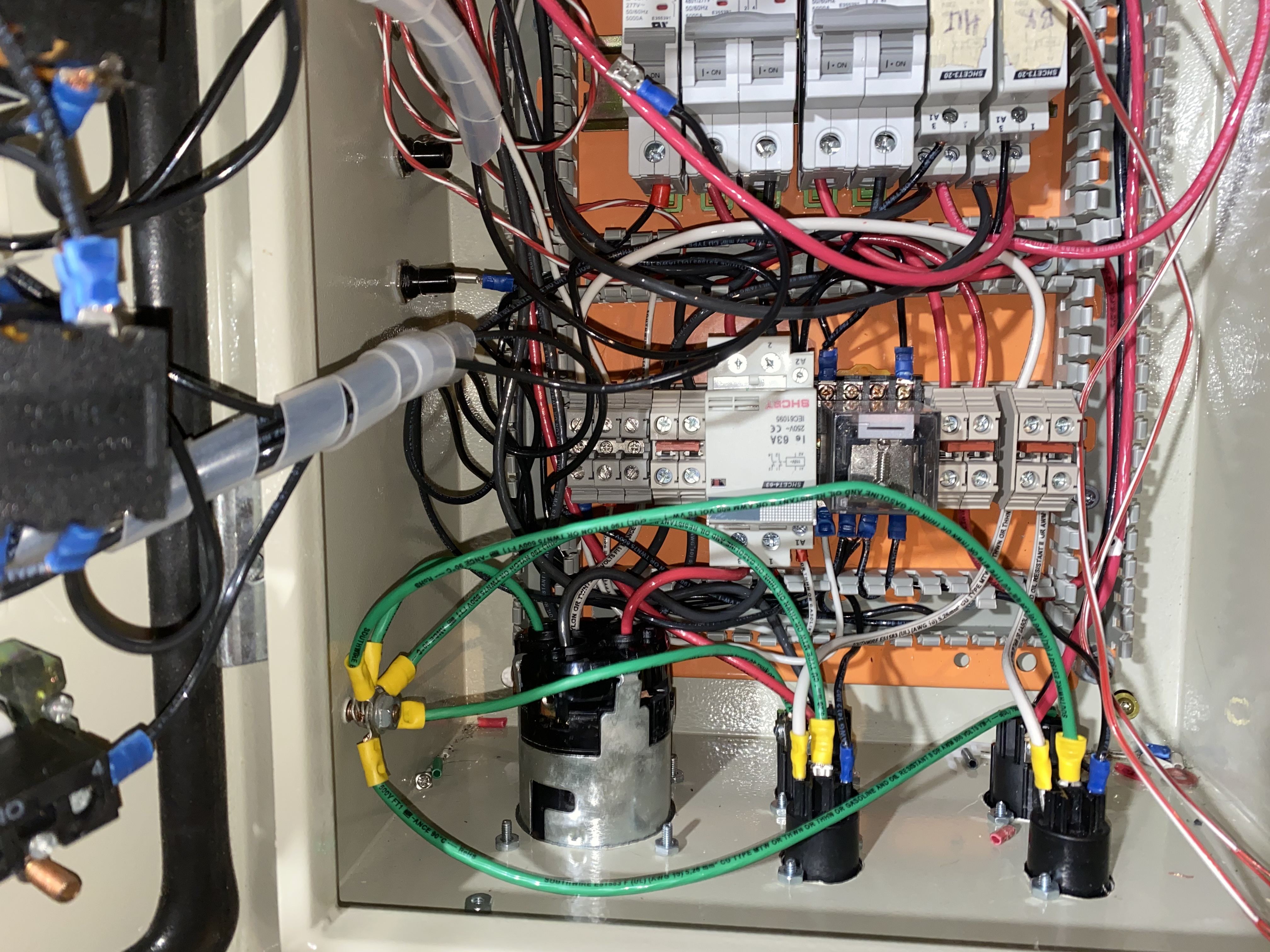
I bought a partially built panel off another HBTer and want to change the plans. I, however, don’t have the experience to plan out the diagram effectively. I attached what I’ve been working with: 240V 50A panel with two pumps and two 5500v elements. The original plan was to run the HLT PID as normal, to run a pump off the mash PID to control mash temp through a herms coil,’and the boil PID is just a dial controller without a temp readout.
i have a two level stand with the HLT above the mashtun with a port draining directly into it. I would like to power a 120V RIMS tube instead of a pump to control mash temp with the pump running off the switch. I’ll keep the 5500v elements in the HLT and BK.
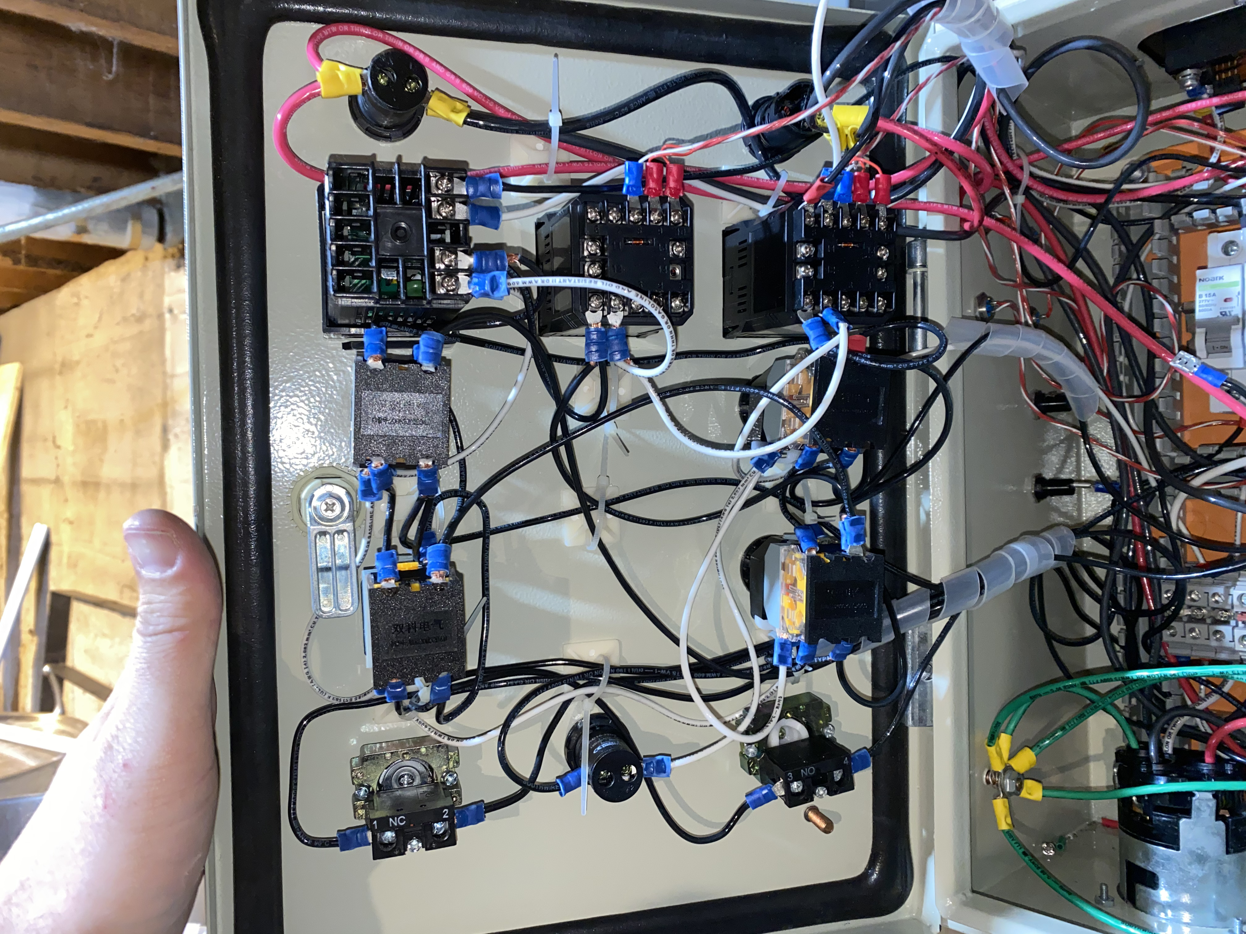
I need help determining the size of the breakers needed; how to take the MLT PID and make it work as a stand alone unit all while making the wort pump switch work with a push button; as a bonus I have an alarm and the tower of power flow meter I’d like to hook up and could use the water pump bottom on the face of the box for that.
I can follow directions I just can’t design them haha.

I bought a partially built panel off another HBTer and want to change the plans. I, however, don’t have the experience to plan out the diagram effectively. I attached what I’ve been working with: 240V 50A panel with two pumps and two 5500v elements. The original plan was to run the HLT PID as normal, to run a pump off the mash PID to control mash temp through a herms coil,’and the boil PID is just a dial controller without a temp readout.
i have a two level stand with the HLT above the mashtun with a port draining directly into it. I would like to power a 120V RIMS tube instead of a pump to control mash temp with the pump running off the switch. I’ll keep the 5500v elements in the HLT and BK.
I need help determining the size of the breakers needed; how to take the MLT PID and make it work as a stand alone unit all while making the wort pump switch work with a push button; as a bonus I have an alarm and the tower of power flow meter I’d like to hook up and could use the water pump bottom on the face of the box for that.
I can follow directions I just can’t design them haha.
Last edited:


![Craft A Brew - Safale BE-256 Yeast - Fermentis - Belgian Ale Dry Yeast - For Belgian & Strong Ales - Ingredients for Home Brewing - Beer Making Supplies - [3 Pack]](https://m.media-amazon.com/images/I/51bcKEwQmWL._SL500_.jpg)