240V is obtained by connecting between two feeds at 120V but that are 180° out of phase with each other, so that when one is positive the other is negative. +120V - (-120V) = 240V. So each of the 120V feeds is a phase. If you measure voltage between two wires with the same phase, you get 0V, but when you measure between two wires of opposite phase, you get 240V. If you measure between either phase and neutral, you get 120V. I like to have all wires of one phase one color, and wires of the other phase a different color.
Inside the spa panel enclosure you have 4 bus bars, one for ground, one for neutral, one for phase 1 and one for phase 2. All the green wires go to the ground bus. All the white wires go to the neutral bus. In your case, the two hot buses are above the 240V breaker, one starts at the center of the breaker and extends to the left, and the other starts at the center and extends to the right (there is a gap between them.) The left half of the 240V breaker connects to the left bus bar, and the right half connects to the right bus bar. The 120V breaker is connected to the right bus bar, so will be the same phase as the right side of the 240V breaker. You have wired the hot on the 120V breaker with black wire (which follows code.) But, you have fed the right bus bar with a red wire, and the load side of the right half of the 240V breaker is connected to a read wire. So when you get into your control panel, you will have one black feed wire at the same phase as the red feed wire, and the other black feed wire at the opposite phase. This can end up causing confusion to someone trying to figure out what is going on inside the panel, and could lead to wiring errors. You can keep the colors separated by phase if you move the red feed wire to the left bus bar, the black feed wire to the right bus bar, move the red load wire to the left half of the 240V breaker, and the black load wire to the right side of the 240V breaker.
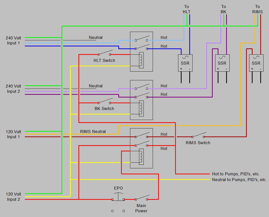
In your enclosure, you will need to have two neutral bus bars, and anything that connects to one cannot connect to the other. In addition you need to have three 120V bus bars, so that the hot from the 120V breaker is separte from the both hots coming from the 240V breaker. All devices receiving power from either of the 120V lines from the 240V breaker must have their neutral connection to the bus connected to the 240V breaker neutral wire. All devices receiving power from the 120V line from the 120V breaker must connect to the neutral bus connected to the neutral bus in the spa panel. The following design is not the same situation as you have, but it shows the separation of hots and neutrals feed from different GFCI protected circuits.
Brew on


![Craft A Brew - Safale BE-256 Yeast - Fermentis - Belgian Ale Dry Yeast - For Belgian & Strong Ales - Ingredients for Home Brewing - Beer Making Supplies - [3 Pack]](https://m.media-amazon.com/images/I/51bcKEwQmWL._SL500_.jpg)


