• Please visit and share your knowledge at our sister communities:
  • If you have not, please join our official Homebrewing Facebook Group!

    Homebrewing Facebook Group

Who wants to check my spa panel wiring?

Homebrew Talk

Help Support Homebrew Talk:

This site may earn a commission from merchant affiliate links, including eBay, Amazon, and others.

WhiteArmadilloBrewing

Well-Known Member
Joined
Jul 28, 2017
Messages
81
Reaction score
5
I believe this is correct wiring of my GFCI protected spa panel as well as the additional 120v breaker that will be connected to/protected by my 20a GFCI outlet.

The more vibrant colored wires are from a 30a dryer outlet and connected to the 50a GFCI breaker then run into my control panel through the bottom center hole. The more muted green,black, and white are direct from the 20a breaker into my control panel to be used specifically for the 20a gfci receptacle.

Would someone be willing to confirm this is correct? Or please correct any mistakes? Thank you!
 

Attachments

  • IMG_5769.JPG
    IMG_5769.JPG
    1.7 MB
From what I can tell, it's wired ok. If it were me, I would swap the red & black 240V feed and load wires side to side, so that all the black load wires are the same phase.

Also (maybe you know this already) don't recombine the neutrals inside your control panel, as that will cause GFCI tripping.

Brew on :mug:

Can you explain why/how you mean re: swapping the red & black so they're on the same phase? (I'm ignorant). I wired this up following a wiring diagram and it didn't mention anything about that.

How do I wire the neutrals inside the control panel without recombining? I planned on using separate bus bars for each wire
 
240V is obtained by connecting between two feeds at 120V but that are 180° out of phase with each other, so that when one is positive the other is negative. +120V - (-120V) = 240V. So each of the 120V feeds is a phase. If you measure voltage between two wires with the same phase, you get 0V, but when you measure between two wires of opposite phase, you get 240V. If you measure between either phase and neutral, you get 120V. I like to have all wires of one phase one color, and wires of the other phase a different color.

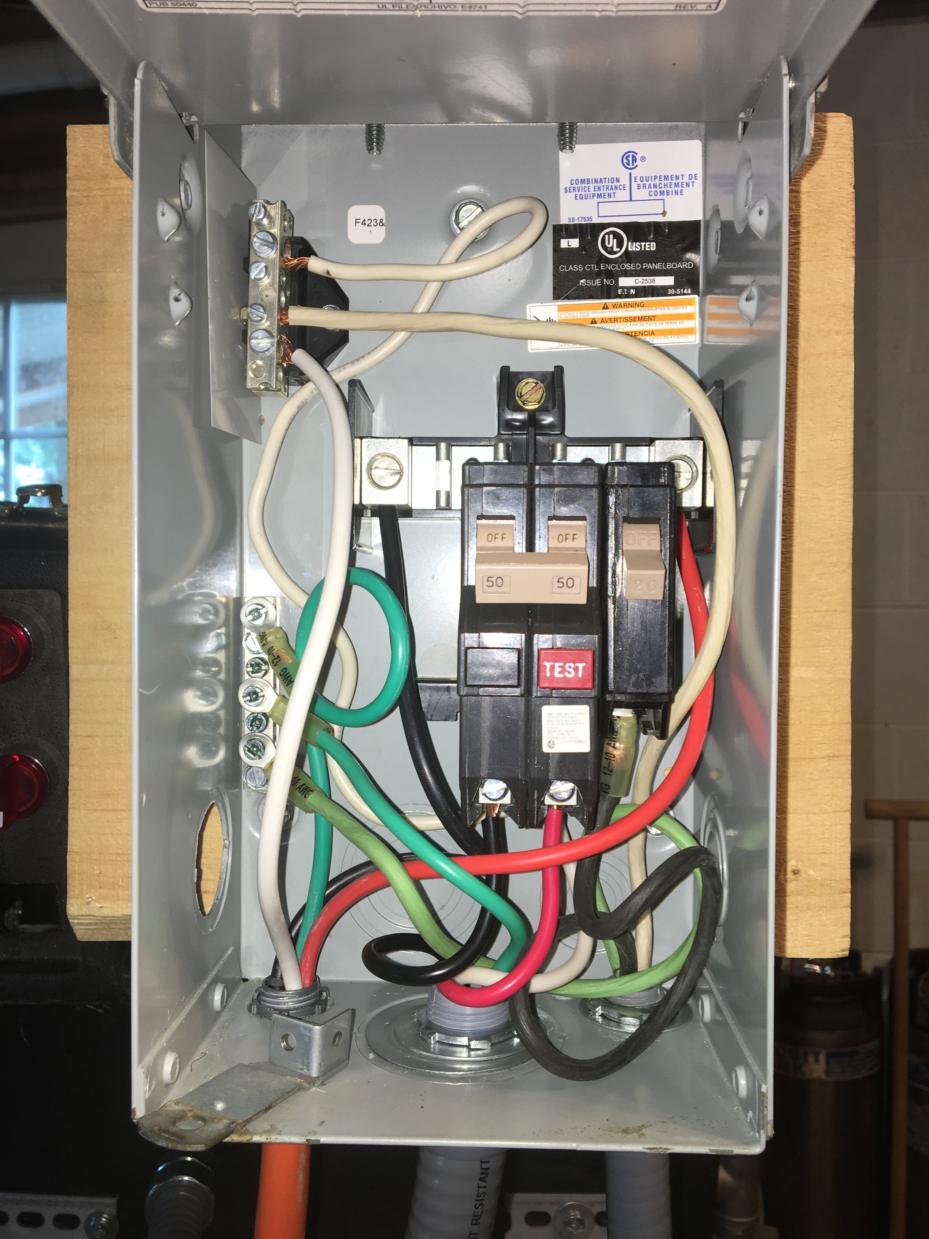
Inside the spa panel enclosure you have 4 bus bars, one for ground, one for neutral, one for phase 1 and one for phase 2. All the green wires go to the ground bus. All the white wires go to the neutral bus. In your case, the two hot buses are above the 240V breaker, one starts at the center of the breaker and extends to the left, and the other starts at the center and extends to the right (there is a gap between them.) The left half of the 240V breaker connects to the left bus bar, and the right half connects to the right bus bar. The 120V breaker is connected to the right bus bar, so will be the same phase as the right side of the 240V breaker. You have wired the hot on the 120V breaker with black wire (which follows code.) But, you have fed the right bus bar with a red wire, and the load side of the right half of the 240V breaker is connected to a read wire. So when you get into your control panel, you will have one black feed wire at the same phase as the red feed wire, and the other black feed wire at the opposite phase. This can end up causing confusion to someone trying to figure out what is going on inside the panel, and could lead to wiring errors. You can keep the colors separated by phase if you move the red feed wire to the left bus bar, the black feed wire to the right bus bar, move the red load wire to the left half of the 240V breaker, and the black load wire to the right side of the 240V breaker.

In your enclosure, you will need to have two neutral bus bars, and anything that connects to one cannot connect to the other. In addition you need to have three 120V bus bars, so that the hot from the 120V breaker is separte from the both hots coming from the 240V breaker. All devices receiving power from either of the 120V lines from the 240V breaker must have their neutral connection to the bus connected to the 240V breaker neutral wire. All devices receiving power from the 120V line from the 120V breaker must connect to the neutral bus connected to the neutral bus in the spa panel. The following design is not the same situation as you have, but it shows the separation of hots and neutrals feed from different GFCI protected circuits.

4 Feed Schematic.JPG


Brew on :mug:
 
Thanks for the thorough explanation. As I parse through this I have one question that I'm hoping will simplify my control panel wiring based on your post above:

My plan was to wire the 120v breaker directly to the GFCI outlet receptacle that my pumps will plug into and that receptacle only. I was going to draw power for the 120v 1500w RIMS element from one of the 120v bus bars powered by one leg of the 240v feed. I think* based on your explanation that would eliminate the need for the additional neutral and 120v bus bar?
 
Sounds like you are starting to understand.

Yes, wiring the 120V feed only to the pump outlet will prevent the cross connection issues I warned about. You do probably want to put a switch between the feed and the pump outlet. If you don't have multiple connections to a power feed you don't have to have bus bars for that feed.

Brew on :mug:
 
Great! If I was planning on splitting the receptacle and connecting a separate switch to both outlets to control the pumps. Would installing a 20a din rail breaker work as an acceptable switch between the feed and the outlet? Or are you referring to a DPST switch?
 
Great! If I was planning on splitting the receptacle and connecting a separate switch to both outlets to control the pumps. Would installing a 20a din rail breaker work as an acceptable switch between the feed and the outlet? Or are you referring to a DPST switch?
I didn't realize you had two pumps. Unfortunately you cannot split the two outlets on a GFCI duplex outlet like you can on an ordinary outlet. So, you're going to have to do something else to get GFCI protection for two separately controlled pumps. You might be better off putting a 20A GFCI breaker in your spa panel.

Brew on :mug:
 
You're welcome. Glad I could be of assistance.

Brew on :mug:

Just want to say that you really go out of your way Doug to help so many here on HBT, especially with the electrical stuff. It takes a lot of time and effort to answer very thoroughly and as detailed as you do. This is part of why this is such a great forum with everyone chiming in to help in the area that they have the knowledge in. I just want to say I appreciate you doing this and I am sure everyone that you helped reading your answers and replies feels the same way!

John

+1000 on that sentiment. In particular, I appreciate your graciousness toward those of us who are trying to learn and be safe at the same time. Too often, for homebrewers like me who do not have a background as an electrician or engineer get ripped for asking questions as if we are actively and intentionally trying to electrocute ourselves or burn our homes to ground.

So, thank you for your patience and wisdom.
 
Back
Top