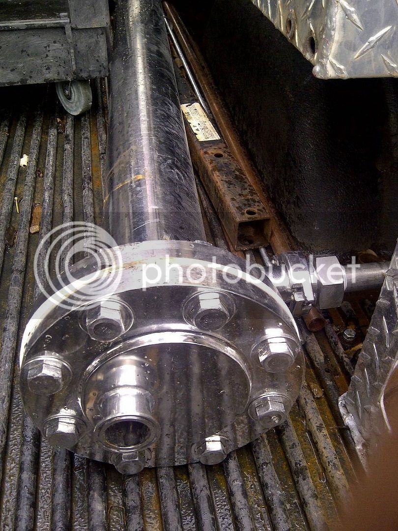
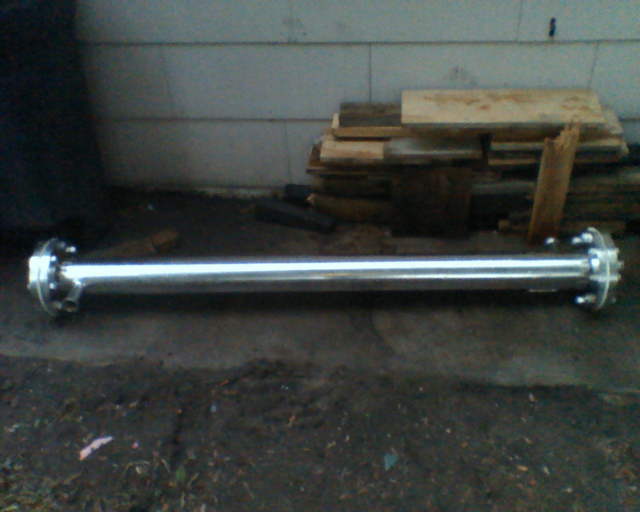
Tube & Shell Heat Exchanger

Homebrew Talk - Beer, Wine, Mead, & Cider Brewing Discussion Forum

Help Support Homebrew Talk - Beer, Wine, Mead, & Cider Brewing Discussion Forum:

This site may earn a commission from merchant affiliate links, including eBay, Amazon, and others.

ScubaSteve

Well-Known Member
Joined
May 21, 2007
Messages
3,673
Reaction score
91
So, after several years of brewing and using a whole myriad of different equipment...I have come to this project. It has been a long time coming, because it requires tools that are beyond the average DIY'er. However, I am not the average DIY'er. ;) Over the last few years, my interests have bounced between welding, machinery restoration, machining, etc. etc. So, now that I have the tools to make big things happen, I thought I would take some spare parts I had laying around, and make them useful.

I had a GEMS Sensors Liquid Level Indicator from about 3 years ago....an Ebay score. These have a magnetic float in the tube that makes the outside "flags" in the sight gauge go red or white based on the position of the magnet. Kept it because it's 316SS and I got it cheap. Plus, it was awesome! The end caps are a burly 3/4" of solid 316SS! And, not to mention, the tube itself is approx 1/8" thick. Doesn't sound like much until you pick it up...this thing was built for a special purpose, and I'm sure it wasn't cheap.


I also got a sight glass that I am going to try and incorporate...it is also heavily built and made from 316SS.


I had to cut off the ends so I could properly drill the holes; I just didn't have the capability to *safely* drill a 15" long cylinder. Plus, the sight gauge had a pair of stainless steel balls inside (LOL) that I had to get rid of. I have a Rage 2 chop saw that is just awesome, I highly recommend it. The blade runs a bit slower than the standard miter saw and actually machines the metal down, kind of like a cold saw, only this one is affordable :) I was sure to go VERY slow because of the thickness/hardness of the material.


Now that I had the ends off, I had to decide what size and configuration of tubing I would use. I did lots of surface area and volume calculations. On a whim I bought some 3/8" SS tube, thinking it would be the best size to prevent clogs. Later, I changed my mind and thought that 1/4" would give a lot more surface area (but require lots more holes and linear feet of tube). In the end I settled on both, to prevent clogging, improve flow, and because I wanted to use the 3/8" tubing I had just bought :D

I had to figure out how to drill through the 3/4" end caps. They don't look like much, but they definitely have some heft to them. From my other adventures with drilling stainless kettles, etc. I knew this was going to be a CHORE. I have a drill press, but didn't think I would have the same precision as my mill. SO, here is my milling machine in use! (CLICK FOR VIDEO!)


And here is where I am at so far....the holes are pretty concentric...I kind of eyeballed things on the mill and it shows. But hey, I'm a novice ;) If I could do it again, I would have put the end caps together and drilled them simultaneously.....but that would have made a difficult job next to impossible. I used cobalt drill bits, LOTS of cutting oil, and patience. Suprisingly, I didn't break a single bit...a good thing since they're $12 a piece!!!!:eek:

Each cap will be welded back onto the main tube, and I will run the thin tubing straight through the small holes...I will then braze them in place with silver solder.


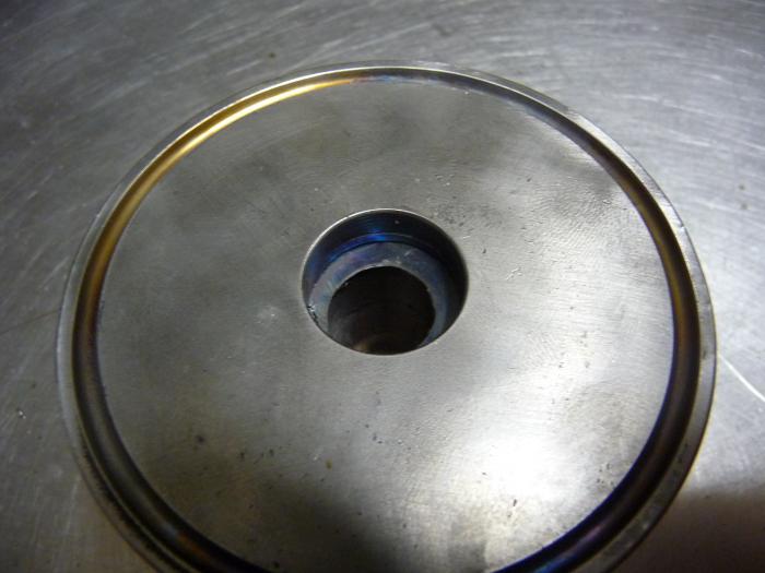
And here's what I got done this weekend...I bored out the water in/out with a 5/8 HSS drill bit. The fitting that was in there tapered down to about 1/4" on the inside, kind of like a flare coupler. So, I had to open it up or the heat exchanger would barely cool.


The finish inside was nowhere near what I achieved with the cobalt bits...but the HSS bit was what I had, and it doesn't matter too much since it will only be water flowing through these channels.


So, here are the parts laid out...I put the tubes in place to help with alignment.


How DARE you! You violated my photobucket! :D Haven't been able to properly roll out the pics with a narrative...
 
i was going to say, i saw this early and was really scratching my head but now its staring to make sense.
i just have to say that mill is stunning, some of the tools in your shop look like they could easily out live the lot of us.
 
AAAAANNNNDDD IT'S TIG TIME!


I got everything setup for tigging this. I chose to fusion weld it because the metal was pretty thick and I knew I could get away with it. It looks like the original weldor did the same. Also, my two handed technique adding the filler rod leaves a lot to be desired.


The Miller MaxStar 150 STH. Haven't used it much, but it earned its keep today! Very smooth, even with the awkward finger amptrol.


Here's my setup...the backgas conveniently went into the water inlet! Argon is heavier than air, so I chose the bottom.


And, here's my welds! Slight undercutting was to be expected with the thickness of metal and heat required. For this application, it doesn't matter. I need to work on my rhythm and consistency so the welds look robotic. The rainbow tint is highly desirable, so I know I was using the right amperage. My auto-darkening helmet's batteries died, so I did this with a fixed shade helmet. Hence the wandering strike marks...:cool:


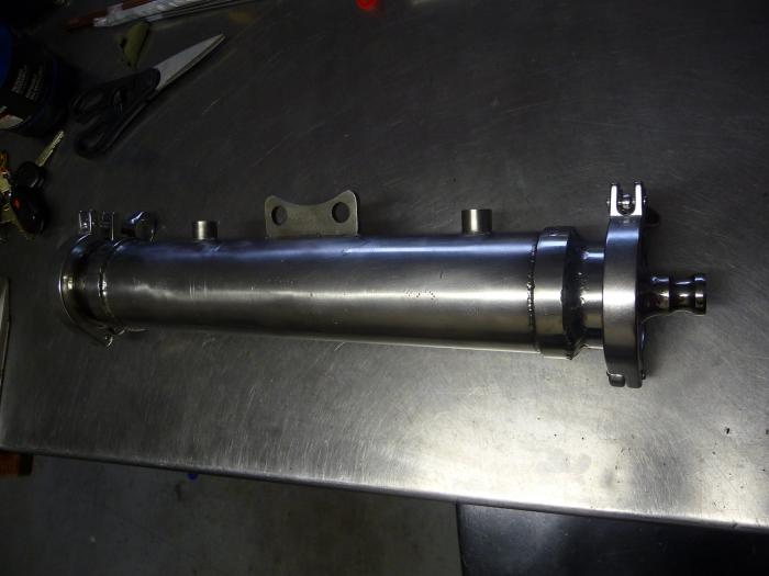
And here is the tube back together again! Still gotta get some 1/4" tube and add that in....then it is on to brazing.


This is awesome! Do you plan to use this to cool or heat wort/water?

But of course....:rockin:

Primarily for chilling, but it could be used as a HERMS too.

I've tried every type of chiller...it's like rock/paper/scissors...they all have their pros and cons...usually where one shines, another fails.

I am hoping that this chiller will have the clean-a-bility of an IC, the cooling performance of a plate chiller, and the resistance to clogging of a CFC.

Because of the difficulty of using a million small tubes like you see in industrial chillers, I compromised and made a hybrid of large and small tube to resist clogging. The large 3/8" tubes are about the same size as most CFC's, so I expect the performance to be somewhere between a plate chiller and coil type CFC. The total linear feet of tubing is 21.25'...right around the length of the bigger CFC's (Chillzilla/Convolutus are 12' of 5/8 OD tube), but with more surface area.

I'm anxious to see how the rest of this goes and how it works when complete. It makes me wonder if something similar could be done with PVC for the outer tube since that would only hold the heating/cooling water. While PVC would not be anywhere near as cool as what you have here, and partially defeat the purpose of this project, it might be a workable alternative for those of us that don't have the tools and knowledge that you do.

What do you have in mind for the manifold section where the wort will enter the smaller tubes? Will that just be a chamber on each end?

There was someone on this forum (can't remember who) that made a version of this with a PVC shell...the internal tubes were copper, but they were a single length of tubing that went "down and back" versus several that go "straight through".

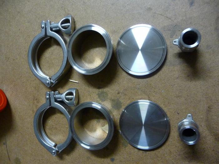
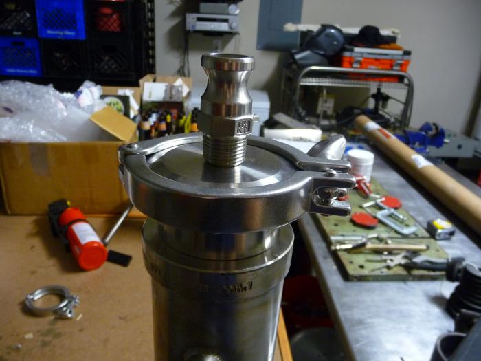
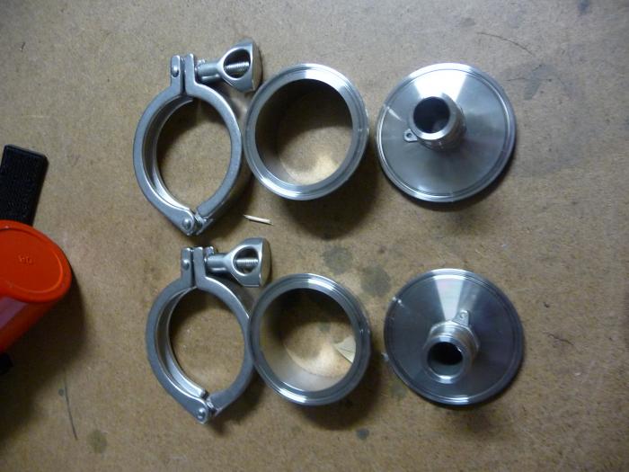
As for the ends, I was thinking of a triclover ferrule...the largest that can fit...probably a 2.5". Then an end cap with a hole in it and male camlock welded on. The triclover clamp could just be opened for direct access to the tubes.
 
Ordered a bunch of supplies last weekend and I have gotten most of them in the mail. I got the 1/4" tubing, hi-temp flux, 35% silver solder (I cheaped out, LOL), and I am really hoping I get the ferrules, end caps, etc. today or tomorrow. I have the next 4 days off and I plan to make the most of it :D
 
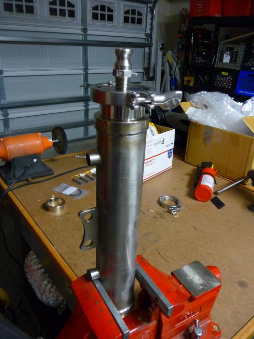
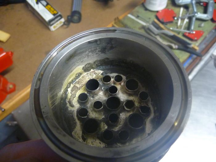
I received the ferrules, endcaps, etc. from Brewer's Hardware...now I am just waiting on the hi temp flux so I can get to brazing...hopefully it'll come tomorrow. I spent the time I had fitting the tubes up properly. I had to enlarge the small holes, what a PITA...lots of drilling and filing. It was all worth it though, because things are coming together!

P1050105.jpg


P1050106.jpg


P1050133.jpg


P1050119.jpg


P1050123.jpg
 
Very nice work and I am 100% jealous. I wish I had your workshop in my garage! A little late now but did you think about adding baffles to the inside for the water to flow aroung? Not sure how much it would help with the cooling. Great work.
 
I did consider the baffles based on some pics I have seen....but it would have complicated things and cost a bit more. The professional units have a perfectly stamped piece of metal with the holes all lined up....it would have been a major PITA to secure it to the inside and still keep everything lined up. As it was, I had a heckuva time getting the tubes installed. At any rate, it probably won't kill the efficiency.

I suppose I could add something through the water ports to create turbulence, but I'll most likely leave it alone.
 
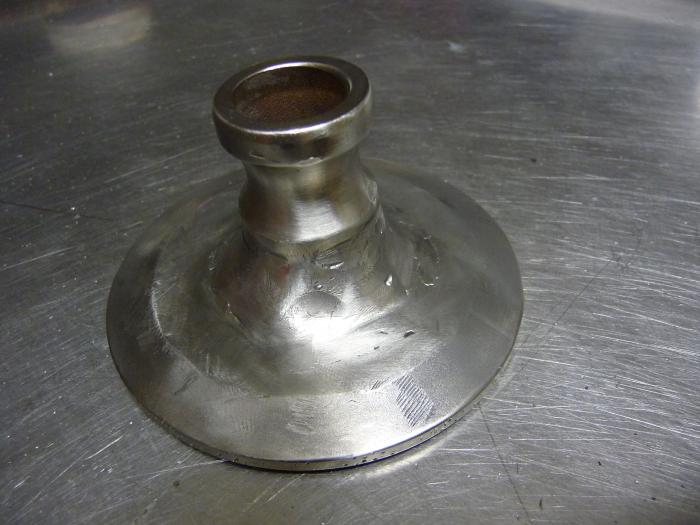
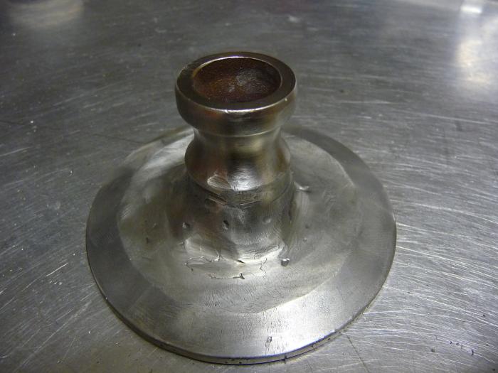
Today was a long day....I'm really frustrated because I had a holiday weekend all lined up to get this done and have nothing to show for it :mad:. Well, the hi-temp flux I ordered still isn't here....so brazing the tubes is out. I tried welding the camlock fittings to the triclover caps, and it was HORRIBLE! No matter what I did, I couldn't get the puddle to flow....the filler just kept piling up and wouldn't blend. I ended up putting way too much heat into the part, which also caused a lot of discoloration. Come to find out, I have been using oxyacetylene filler rods....not TIG rods...I guess they are different enough to cause significant issues :( I ended up running out of argon, wasting an afternoon, and am probably going to have to scrap one TC end cap and camlock....here is what I ended up with...still useable on something else, but not on this project, I'm afraid.

P1050143.jpg


P1050145.jpg


P1050146.jpg
 
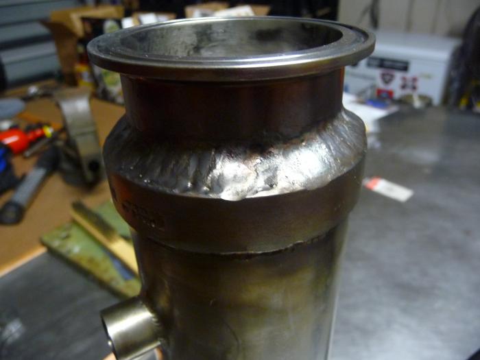
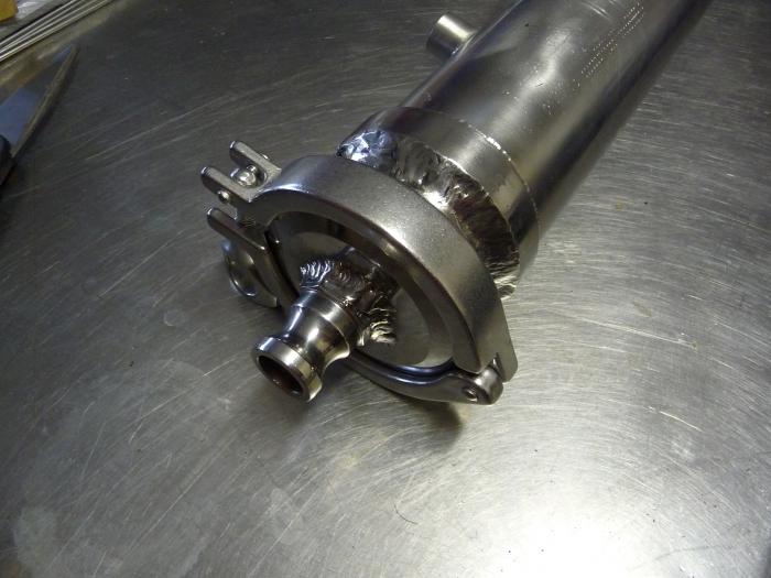
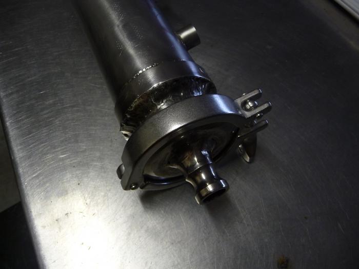
Okay, so here is the latest. Made quite a bit of progress over the last few weeks. First of all, I know the welds look like crap. Because of my inexperience, I had several technical difficulties with the welder and couldn't get enough amperage (panel knob set too low)...as a result, I used way too much filler to even get a weld...not to mention that I should have used 1/16" rod and tungsten versus 3/32". I ended up rolling with the punches and had to grind out a lot of the welds. They still look like crap, but they will get the job done.
P1050165.jpg


P1050166.jpg


P1050187.jpg
 
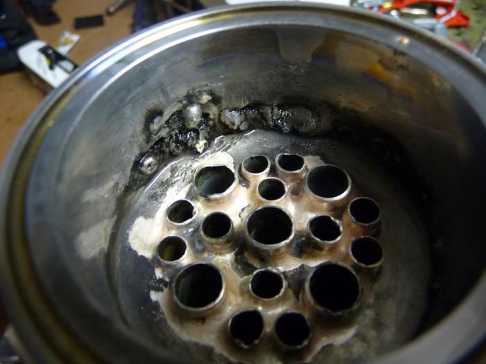
Then I silver soldered the tubes in. Due to the crappy welding, I ended up with a lot of sugaring on the inside. Yes, I made sure I had a purge in place, but there must have been a leak. The tubes going through the body of the chiller probably caused a loss of shielding gas, even though I covered them with foil. I really shouldn't have taken on a project with this level of difficulty without more TIG experience, but I have learned a lot...the hard way. At any rate, I salvaged things and tried to create a smoother surface by filling irregularities with plumbing solder on the inlet/outlet. I also consider it to be insurance against corrosion where the sugaring caused a loss of chromium.

It's not perfect by any means, but I am learning a lot and don't have too much money into it since I already had the main section lying around. The good news is that I can clean this chiller much better than a plate or CFC (which is the whole point of this experiment!).

P1050169.jpg


P1050171.jpg


P1050196.jpg
 
Man, I know my welding sux...but I've never seen a thread with stainless steel welding get less discussion than this one! I know that sounds vain, but I see a lot of the same types of threads over and over and OVER again on this forum (is it done yet, is it infected, will this work, etc. etc.)....this is a different kind of build; a departure from the norm and only a few people seem involved. Maybe it's out of the scope of homebrewing?
 
I'm watching! I think the pics speak for themselves, a wet run will probably bring about some conversation. If it works well I may turn a SS filter housing into something similar but I'll have to braze it since I don't own a TIG, yet.
 
I like it! Keep up the good work. I was thinking about making a flash boiler along similar lines a while back... I ran into several pro brewers at the GABF who are always amazed at the innovation and effort that homebrewers put in to custom tailor their rigs or gain an extra few points of efficiency.
 
LOL...thanks guys:p

I'll definitely be doing a video once I get the water side plumbed. Prolly gonna order those fittings today since its Black Friday and all.
 
So you're running wort through the tubes, and filling the shell with water? I guess because of where your ins and outs are located it works better that way. Do you have a way to increase the turbulence of the wort flow?
 
I too am very interested in how it cools. I always wanted to build one out of PVC and copper like the other guy did here on the board, but I always thought there should be a cleaner way to do it. Build looks great!
 
Very cool! Working at a chemical plant, I see heat exchangers all the time. Very cool what you are doing and I admire your ability to try new things and learn. Keep up the good work!
 
I it doesn't end up working I'll trade you my spare and see i I can make a go at getting it right....
drunk4zc.gif


I'm assuming you will be mounting it horizontally with the water connections pointing up to fully flood the shell, but with the wort out at the center of the cap will your tubes only fill to just above half and then become air bound since the air can't be vented from the top tubes above the wort outlet? Would an outlet cap with the connection all the way at the top allow all the air out of the tubes?
 
So I absolutely did not need another project to start but this has got my attention peaked. Great job so far, I might have to borrow from the concept and start my own. Can't wait to see how it turns out.
 
WPStrassburg said:
I it doesn't end up working I'll trade you my spare and see i I can make a go at getting it right.... http://s9.photobucket.com/user/w_strassburg/media/Beer/Untitled.jpg.html http://s9.photobucket.com/user/w_strassburg/media/Beer/0603122034a.jpg.html I'm assuming you will be mounting it horizontally with the water connections pointing up to fully flood the shell, but with the wort out at the center of the cap will your tubes only fill to just above half and then become air bound since the air can't be vented from the top tubes above the wort outlet? Would an outlet cap with the connection all the way at the top allow all the air out of the tubes?

I'm curious about this too. My experience with shell and tube is in steam cookers. The steam runs through the tubes at constant pressure, and the shell is filled with product from bottom to top in a vertical arrangement. That type usually has baffles in the tube to create turbulence and improve performance. Short residence time is key. Not exactly necessary to run it that way. Distillation condensers run the opposite way, with water filling the jacket that surrounds the coil. There, path length is critical. It just depends on application. Cool project.
 
IMO wort should be in tubes, and apparatus should be designed with large tri-clover fittings so tubes can be cleaned between uses with bottle brush. Propylene glycol or preheat water to HLT through shell.
 
This is fantastic!!!! I have a similar design that I've had drawn up in Solidworks for some time now but I couldn't figure out a good way to close the ends down to one point and the triclover ferrule is perfect! My design will include baffles, they don't need to be perfect like the pro versions but they do increase utilization significantly (if I remember right from my Thermodynamics courses in college:confused:). My plan is to use cooled refrigerant through the tubes and beer through the shell. It looks like you are doing beer through the tubes and water through the shell, am I right? I am not sure that beer through the shell is better but it minimizes the amount of refrigerant I have to use. Great work man! I'm sure you can't wait to get this thing working. By the way, you are right, this design is tough to build but I think it really is the best of all worlds although it still wont be as easy to clean as an IC but it'll be wayyy better than a plate chiller! I would look into cooling using refrigerant or glycol now that you have such a sealed system; with glycol or refrigerant you could use this year-round with no temperature difference.
 
By the way, you are right, this design is tough to build but I think it really is the best of all worlds although it still wont be as easy to clean as an IC but it'll be wayyy better than a plate chiller!

I'm really interested to see the HEX perf out of this thing. Would it be safe to classify this as a sub-category under "counterflow chiller"? -Seems like it to me, but just curious what the consensus is.

This should be far easier to clean than either a plate OR a double tube/ hose counterflow chiller as the wort flows through straight pipes; the flow restriction should be very low so it makes a good performance chiller that can be used with recirculation back into the kettle. It can also be easily cleaned with a dip tube brush down each tube.

It is also less work to tear it down and it takes less space than some of the new style counter flow chillers (not sure what to call these): http://jadedbrewing.com/collections/counterflow-chillers/products/jaded-counterflow-chiller-cfc

The tube and shell design should involve less restriction than the Jaded-style CFCs, too as you don't have those constant 180 degree turns in the wort flow.


Adam
 
Back
Top