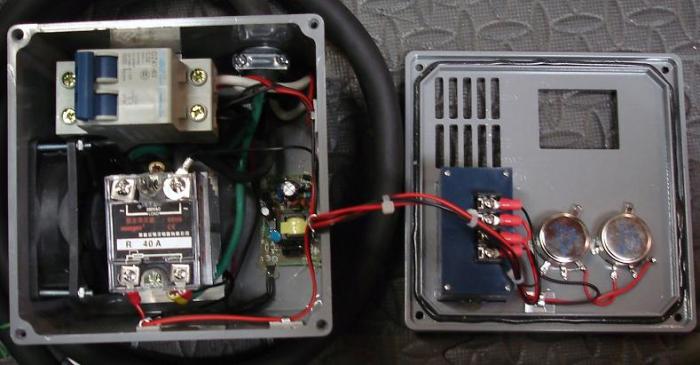
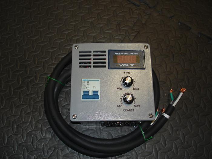
StillDragon DIY Controller Kit

Homebrew Talk - Beer, Wine, Mead, & Cider Brewing Discussion Forum

Help Support Homebrew Talk - Beer, Wine, Mead, & Cider Brewing Discussion Forum:

This site may earn a commission from merchant affiliate links, including eBay, Amazon, and others.
Also, I just double checked my wiring in the garage I used for my Welder. I'm pretty sure that is 8 gauge wire, that I used for my 30A setup for it. I know that is HHG. I'm thinking I may just leave that alone, and wire up a new 20A 240V setup, since I have a large amount of 10 gauge 10/3 HHNG wire. I'll just cap and tape up the N wire on both sides. So at this point, I'm thinking of picking up 20A 240V breaker and 3 prong 20A 240V outlet.

I just have to figure out the cheapest way to go with GFCI, I just realized my first link for that was a 120V version, so ignore that.
 
To measure voltage on element you need to connect it in parallel to element (black wire to to one SSVRvoutput red wire to second hot which going straight to element. And you need to put any hot leg through that black transformer (ring). But be aware - power supply inside that meter doesn't like chopped sin wave produced by SSVR so you have a good chance to burn it out.

So I'd reccomend to connect black wire to SSVR in. This way voltmeter will show not the voltange on an element but your mains voltage (ie 240v). But you will see changing amps going through an element.

Ok, you are saying black wire on the power in, on the SSR, and the red wire on the power out in the SSR going to the element. I know I need to hook the ring in to, that has inputs on the back of the meter for it. If this does burn out for some reason, it was less than $10 anyhow.
 
Ok, you are saying black wire on the power in, on the SSR, and the red wire on the power out in the SSR going to the element. I know I need to hook the ring in to, that has inputs on the back of the meter for it. If this does burn out for some reason, it was less than $10 anyhow.
No, one wire from meter (doesn't matter black or red) to SSVR out and another wire from meter to your second hot leg which is not connected to SSVR
 
No, one wire from meter (doesn't matter black or red) to SSVR out and another wire from meter to your second hot leg which is not connected to SSVR

Ok, I will have to cut that wire then, twist it up, put a nut on it and tape it then. Since that wire doesn't go into the SSR, it goes straight from the outlet to the element, I had planned on just running it straight through the box, I guess I could cut it and hook that up. I currently use Cutler Hammer breakers in my box in my garage, how would I know if that link you gave me for that breaker would work in my box?

I think I'm going to swing by lowes tomorrow and look into buying a junction box. The box that came with my kit is a little small IMO. I think I will by a switch as well, to be able to turn the power on and off. I'll see if I can't find a box about twice the size as the one that came with mine.
 
I currently use Cutler Hammer breakers in my box in my garage, how would I know if that link you gave me for that breaker would work in my box?

.
I have not exactly the same but similar GFCI breaker. Works fine. You can install it in the controller box and use as a switch.
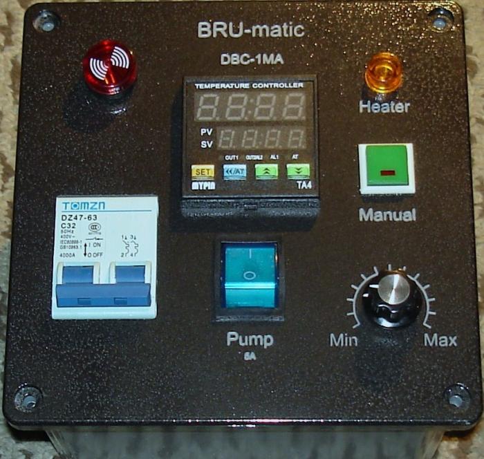
 
I have not exactly the same but similar GFCI breaker. Works fine. You can install it in the controller box and use as a switch.

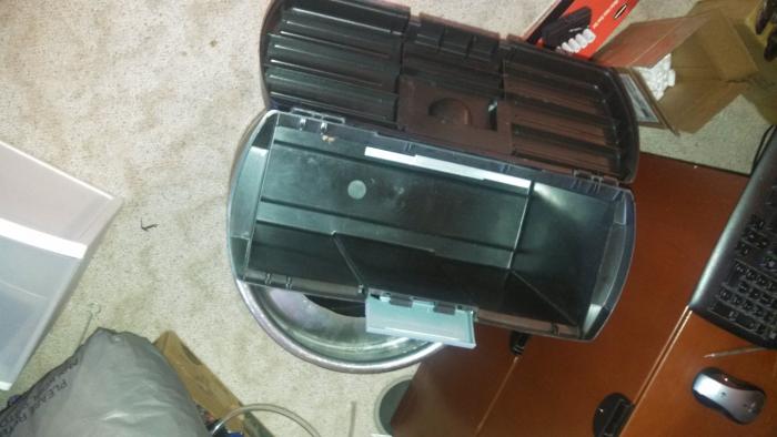
Ahh interesting idea. Do you have a picture of your setup? As far as electrical boxes go, the plastic one that came in my kit is way too small. Would any thick plastic container work for a electrical box with this setup, I was going to see if I had an old plastic tool box or something like that to use instead. So this GFCI Breaker, it basically has HHG IN, and HHG OUT?

I'm also wondering if my current HHG 30A 240V Welding Outlet could be used now, and create a plug for it and run that into this GFCI Breaker?
 
This GFCI breaker has HH in/out, It monitors the balance between that two hots. If disbalance happened due to a leak it trips.
And yes you can use 6x6x4 (~$12) or 8x8x4 (~$21) plastic boxes from homedepot or lowes.
I don't have a picture of controler with GFCI breaker, but has a picture of controller mounted in 6x6x4 plastic box (similar to HighGravity SV)

Black_front.jpg
 
This GFCI breaker has HH in/out, It monitors the balance between that two hots. If disbalance happened due to a leak it trips.
And yes you can use 6x6x4 (~$12) or 8x8x4 (~$21) plastic boxes from homedepot or lowes.
I don't have a picture of controler with GFCI breaker, but has a picture of controller mounted in 6x6x4 plastic box (similar to HighGravity SV)

Very nice looking, I went ahead and ordered that breaker, hopefully I get it before April like it's saying. Did you run the grounds on the in and out, to the SSR grounds then? So do you think using my current 30A setup would be fine then? Here is a box I was thinking of using :tank: Put the SSR on a small stand on the bottom, drill some holes for helping with heat. And then mounting the voltage/Amp meter on the back, along with the switch. Also, thank you for answering all of your questions.
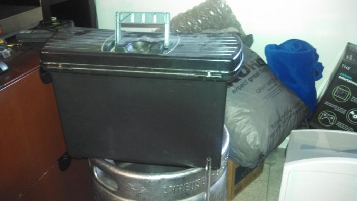
plasticelectricbox 001.jpg


plasticelectricbox 002.jpg
 
I may just go buy a 8x8x4 from lowe's then. I want to make sure I have plenty of room in there, incase I want to add a fan. Thanks again for your help.
 
I went ahead and picked up the 8x8x4 box today from Lowe's and picked up about 10' of 10/3 flexible wire, so that I can start working on this. Thanks again for all of the responses.
 
I have one more question, is any size wire fine for the potentiometer? I cut up an older extension cord we weren't using anymore and pull the wire from that, that I used in my stir plate. I still have a lot of that left over, wondering if I can use that for the POT?

Also, is it necessary to solder to the potentiometer, or can you just use some wire clips and connect to it that way?

Any size wire would do. And no you don't need to solder. The connectors don't work too well though, the smaller ones work ok. I just sent the wire through the hole, twisted it and then heat shrink tubing to seal it.
 
Any size wire would do. And no you don't need to solder. The connectors don't work too well though, the smaller ones work ok. I just sent the wire through the hole, twisted it and then heat shrink tubing to seal it.

Ok, thanks, I'll pick some of that up.
 
Anyone know how the Still Dragon controller works on 120? I know the pot that's shipped is rated for 240/60Hz, where a 120/60Hz pot from Auber is 1.6Kohm instead of 4.5Kohm. A new pot is cheap enough, just wondering on performance.
 
Yes it works for 110V. Just you will have a half of resolution (first po half-turn will be no output). To fix a resolution problem you need a 220KOhm or 250KOhm pot.
 
I have one more question, is any size wire fine for the potentiometer? I cut up an older extension cord we weren't using anymore and pull the wire from that, that I used in my stir plate. I still have a lot of that left over, wondering if I can use that for the POT?

Also, is it necessary to solder to the potentiometer, or can you just use some wire clips and connect to it that way?

The wire needs to be rated for mains voltage and 2W same as the potentiometer. In practice anything except the thinnest hook up wire will be OK.
 
Wow, good find. You could add another gfci for a 120 circuit as well, and be all set. Sure looks better than my spa panel

Sent from my SCH-I545 using Home Brew mobile app
 
If you aren't using 120 Volt (no 120v pump, PID powered by both hots etc ).you can install this GFCI:
http://www.ebay.com/itm/DIN-Rail-Mo...age-Circuit-Breaker-AC-230V-32A-/310571189555
or similar.

That looks great. 30ma sensitivity with less than 0.1s response time should be perfectly adequate, if I read the inverse-time curve charts correctly.

Back to the drawing board, lol.

Addendum: It looks like if I were to go with this GFCI and a 120v 15a duplex GFCI outlet, and change my plan to use DIN rail components, then I would net about $60 under the spa panel solution, with a cleaner build. YMMV
 
After pondering this a bit more, wouldn't you need a completely separate power feed for 120v? It seems to me that if you were to derive a 120v circuit from one leg of the 240v, this GFI would trip if current flowed through the neutral, unbalancing the two hots. Am I missing something here?
 
Not true, a 240V GFCI breaker manages 120V fine. It senses current between the red, white and black wires and as long as all three are in balance the breaker is happy. Only when the three are not in balance - current returning on the green wire or passing to ground, will the GFCI trip.

A connection between the red or black wire to white will be 120 VAC.

The GFCI in the link is 2 wire, not 3.

The little diagram shows the flux coil around only two wires, i.e., it is verifying that current down one leg = current back up the other. If you were to run a 120v circuit on this, the current down one hot leg would come back on the neutral, and appear like a ground fault. So that doesn't work.

If you have the two GFCI circuits in parallel, they should act just fine though. You are just creating two separate circuits, both with their own protection.

The problem is that you would then need 2 cords going between the panel and wherever your GFCI protection circuit enclosure is. You do not want the GFCI (or GFCIs) where the rest of the control electronics are.
 
As an aside, many households here in the states now have the 4 conductor plug/receptacles for the range and dryer circuits. Previously the 3 conductor solution would have been typical. But modern appliances now have control panel accessories (think clock) that are energized with 110/120 volts.

Previously the ground wire would have been used also as a neutral and then the clock would piggy back off of one of the 110/120 volt legs.
Evidently this became a no no. And so enter the 4 conductor solution we now see more and more of. Where by an extra wire would be needed to energize the lower voltage control panels on the modern appliances.

The StillDragon controllers are set up for HHG. However if you wish to add a 120 volt fan to your box, please do take advantage of your 4 conductor accommodation.

For setting up a "replacement" plug head for your service cord, simply do not install the contactor that would ordinarily be used to facilitate the neutral wire.

#10 service cord is recommended. Get the kind that has the soft rubber jacket. It's about $2 per ft.

The 300 volt is best if you want it to fit our PG-19 strain relief glands. The 600 volt will require a much larger gland.....Sorry I don't know how large.

The 300 volt service cord has a Blk/Wht/Grn set of wires. If you find the white wire to be too confusing then simply wrap some black or red electrical tape around it to identify it as HOT.

We do also offer larger size boxes for those of you who wish to add extra bells and whistles (or fans) to your control systems.

Though most systems (with a 5500 watt element) will not likely pull more than 22 amps, I am nearly positive your AHJ (building department) would insist on a 30 amp dedicated circuit if your work were to be inspected? They may accept a 25 amp? But I suspect many of you are not having your electrical work inspected.

Hope this helps.

Cheers
Larry
 
The peeps on the still dragon site are putting fans in their boxes. I thought drilling out some holes for vent would be sufficient?

http://www.stilldragon.org/discussion/comment/8961#Comment_8961

The holes are sufficient. I have been using one of these for about 5 years with out any issues. However many of our customers are installing fans to insure that they get an optimal service life out of the controller.

Furthermore, some users are installing multiple control stations in one (larger) box and so a fan in this instance would be best for displacing the heat generated.

I hope this helps
Larry
 
Perhaps I was being rather too charitable. This is the point that I was trying to get across.

The kit is advertised as a 5500W controller. But Lloyd StillDragon recommends a fan to operate at 5500W. So why isn't the fan in the kit :|

Firstly, the controller that we offer is originally intended for distilling. The 5500 watts (on a 5-10 gallon kettle charge) is only for rapid heat up. Once running temps are achieved, the controller would typically be dial back to 2200-3000 watts or so.

Secondly, the kits are just that. Kits to be assembled, modified, pimped out by the end user. For what is included, we really do offer the best value available.
All of the parts can also be ordered individually in case the end user wishes to source any other components else where.

I hope this helps.
 
Here is an example with no fan but does have a digital meter that displays Amperage and voltage.

little controller.jpg
 
Here is an example of a 3 station (element) controller. With this unit, a fan is used to help rapidly shed heat.

3 station controller.jpg
 
Glad I stumbled upon this. It'll help control my heating elements a hell of a lot easier.
 
This 3 wire breaker youve referenced is for only 240 right? Then if I want a simple 120 outlet for my pump then I'd need the four wire type breakers?
 

Latest posts

Back
Top