• Please visit and share your knowledge at our sister communities:
  • If you have not, please join our official Homebrewing Facebook Group!

    Homebrewing Facebook Group

StillDragon DIY Controller Kit

Homebrew Talk

Help Support Homebrew Talk:

This site may earn a commission from merchant affiliate links, including eBay, Amazon, and others.
Ok, so I have a couple of questions about this. I just got this kit. The only wire I could fine in my garage was 10/4. I'll have to check my 30A outlet in their, it "may" be 10/3 but I"ll double check.

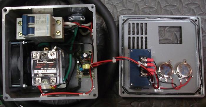
If I were to use the 10/4, basically I would run 1 hot into the SSR #1 input(from the outlet), and the hot from the SSR #2 input going to the heating element. The other hot, would just go straight through, from the outlet, into the other input on the heating element. The ground would go from the outlet, into the ground on the SSR, then the other ground from the SSR would go to the ground screw on my keggle element container. Then I should just cap of the neutral on the outlet side, run it straight through the box, and then cap it on the keggle side? Does that all sound right?

Question #2, if I wanted to also wire in a voltage/amp reader. Would 1 wire go to the hot in, and the other wire to the hot out, is it that simple?
that should work... although I strongly advise a GFCI.

10/3 has 4 wires btw they dont count the ground as a wire for some reason...
 
that should work... although I strongly advise a GFCI.

10/3 has 4 wires btw they dont count the ground as a wire for some reason...

I will see if I can check my welding wire outlet and see if that is HHG and not HHNG. My understanding between 10/3 and 10/4, they both have ground wires, but the 10/4 one, the ground has a covering on it like the other wires.

Anyone have a link for reasonable GFCI options, most of the breakers I see are double or triple the price I just paid for this controller kit :-(
 
I will see if I can check my welding wire outlet and see if that is HHG and not HHNG. My understanding between 10/3 and 10/4, they both have ground wires, but the 10/4 one, the ground has a covering on it like the other wires.


Anyone have a link for reasonable GFCI options, most of the breakers I see are double or triple the price I just paid for this controller kit :-(


I got my gfi spa panel at lowes for around 50$. Then the cost of running 10/3 line in and out made it around 100$ (plugs and receptacles included).
 
There are inline 20A gfci units that are much cheaper than $50 which will work if you go with a 4500w element instead of the 5500w ... I use the 4500w elements and they are plenty for 5 or 10 gallon batches..

I totally agree the extra cost stinks but in the long run even $50 is nothing compared to the piece of mind and the life it could save...

You know, I do have a 4500W element right now, not a 5500W, now that I think about it. Here is my question though, that puts it at 18.75A requirement. Is there any surge amperage when you fire this up, that could cause it to go over 20A and trip the breaker? Or I suppose I could set my Potentiometer at 75% at startup and not worry about that? You thoughts?

As afar as inline units, is this what you are talking about?

http://www.amazon.com/dp/B00279LG50/?tag=skimlinks_replacement-20
 
Last edited by a moderator:
No there is no surge since it pure resistive load. However I'd reccomend to set potentiometer to "min" position every time when you switching your controller on or off.
 
To measure voltage on element you need to connect it in parallel to element (black wire to to one SSVRvoutput red wire to second hot which going straight to element. And you need to put any hot leg through that black transformer (ring). But be aware - power supply inside that meter doesn't like chopped sin wave produced by SSVR so you have a good chance to burn it out.

So I'd reccomend to connect black wire to SSVR in. This way voltmeter will show not the voltange on an element but your mains voltage (ie 240v). But you will see changing amps going through an element.
 
Also, I just double checked my wiring in the garage I used for my Welder. I'm pretty sure that is 8 gauge wire, that I used for my 30A setup for it. I know that is HHG. I'm thinking I may just leave that alone, and wire up a new 20A 240V setup, since I have a large amount of 10 gauge 10/3 HHNG wire. I'll just cap and tape up the N wire on both sides. So at this point, I'm thinking of picking up 20A 240V breaker and 3 prong 20A 240V outlet.

I just have to figure out the cheapest way to go with GFCI, I just realized my first link for that was a 120V version, so ignore that.
 
To measure voltage on element you need to connect it in parallel to element (black wire to to one SSVRvoutput red wire to second hot which going straight to element. And you need to put any hot leg through that black transformer (ring). But be aware - power supply inside that meter doesn't like chopped sin wave produced by SSVR so you have a good chance to burn it out.

So I'd reccomend to connect black wire to SSVR in. This way voltmeter will show not the voltange on an element but your mains voltage (ie 240v). But you will see changing amps going through an element.

Ok, you are saying black wire on the power in, on the SSR, and the red wire on the power out in the SSR going to the element. I know I need to hook the ring in to, that has inputs on the back of the meter for it. If this does burn out for some reason, it was less than $10 anyhow.
 
Ok, you are saying black wire on the power in, on the SSR, and the red wire on the power out in the SSR going to the element. I know I need to hook the ring in to, that has inputs on the back of the meter for it. If this does burn out for some reason, it was less than $10 anyhow.
No, one wire from meter (doesn't matter black or red) to SSVR out and another wire from meter to your second hot leg which is not connected to SSVR
 
No, one wire from meter (doesn't matter black or red) to SSVR out and another wire from meter to your second hot leg which is not connected to SSVR

Ok, I will have to cut that wire then, twist it up, put a nut on it and tape it then. Since that wire doesn't go into the SSR, it goes straight from the outlet to the element, I had planned on just running it straight through the box, I guess I could cut it and hook that up. I currently use Cutler Hammer breakers in my box in my garage, how would I know if that link you gave me for that breaker would work in my box?

I think I'm going to swing by lowes tomorrow and look into buying a junction box. The box that came with my kit is a little small IMO. I think I will by a switch as well, to be able to turn the power on and off. I'll see if I can't find a box about twice the size as the one that came with mine.
 
I currently use Cutler Hammer breakers in my box in my garage, how would I know if that link you gave me for that breaker would work in my box?

.
I have not exactly the same but similar GFCI breaker. Works fine. You can install it in the controller box and use as a switch.
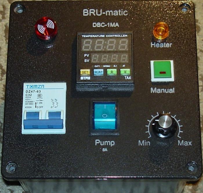
 
I have not exactly the same but similar GFCI breaker. Works fine. You can install it in the controller box and use as a switch.

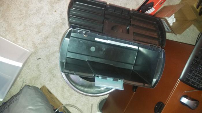
Ahh interesting idea. Do you have a picture of your setup? As far as electrical boxes go, the plastic one that came in my kit is way too small. Would any thick plastic container work for a electrical box with this setup, I was going to see if I had an old plastic tool box or something like that to use instead. So this GFCI Breaker, it basically has HHG IN, and HHG OUT?

I'm also wondering if my current HHG 30A 240V Welding Outlet could be used now, and create a plug for it and run that into this GFCI Breaker?
 
This GFCI breaker has HH in/out, It monitors the balance between that two hots. If disbalance happened due to a leak it trips.
And yes you can use 6x6x4 (~$12) or 8x8x4 (~$21) plastic boxes from homedepot or lowes.
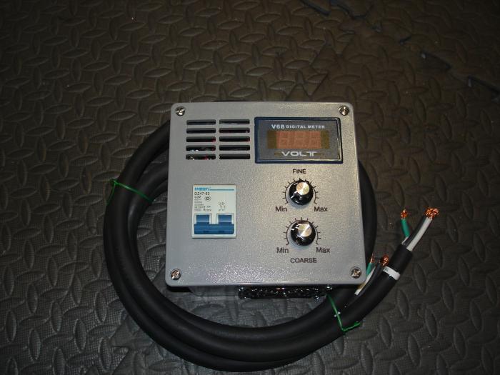
I don't have a picture of controler with GFCI breaker, but has a picture of controller mounted in 6x6x4 plastic box (similar to HighGravity SV)

Black_front.jpg
 
This GFCI breaker has HH in/out, It monitors the balance between that two hots. If disbalance happened due to a leak it trips.
And yes you can use 6x6x4 (~$12) or 8x8x4 (~$21) plastic boxes from homedepot or lowes.
I don't have a picture of controler with GFCI breaker, but has a picture of controller mounted in 6x6x4 plastic box (similar to HighGravity SV)

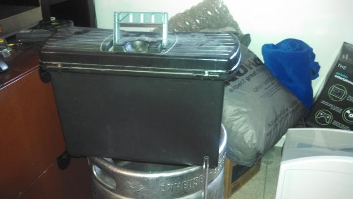
Very nice looking, I went ahead and ordered that breaker, hopefully I get it before April like it's saying. Did you run the grounds on the in and out, to the SSR grounds then? So do you think using my current 30A setup would be fine then? Here is a box I was thinking of using :tank: Put the SSR on a small stand on the bottom, drill some holes for helping with heat. And then mounting the voltage/Amp meter on the back, along with the switch. Also, thank you for answering all of your questions.
plasticelectricbox 001.jpg


plasticelectricbox 002.jpg
 
I may just go buy a 8x8x4 from lowe's then. I want to make sure I have plenty of room in there, incase I want to add a fan. Thanks again for your help.
 
I went ahead and picked up the 8x8x4 box today from Lowe's and picked up about 10' of 10/3 flexible wire, so that I can start working on this. Thanks again for all of the responses.
 
I have one more question, is any size wire fine for the potentiometer? I cut up an older extension cord we weren't using anymore and pull the wire from that, that I used in my stir plate. I still have a lot of that left over, wondering if I can use that for the POT?

Also, is it necessary to solder to the potentiometer, or can you just use some wire clips and connect to it that way?

Any size wire would do. And no you don't need to solder. The connectors don't work too well though, the smaller ones work ok. I just sent the wire through the hole, twisted it and then heat shrink tubing to seal it.
 
Any size wire would do. And no you don't need to solder. The connectors don't work too well though, the smaller ones work ok. I just sent the wire through the hole, twisted it and then heat shrink tubing to seal it.

Ok, thanks, I'll pick some of that up.
 
Anyone know how the Still Dragon controller works on 120? I know the pot that's shipped is rated for 240/60Hz, where a 120/60Hz pot from Auber is 1.6Kohm instead of 4.5Kohm. A new pot is cheap enough, just wondering on performance.
 
Yes it works for 110V. Just you will have a half of resolution (first po half-turn will be no output). To fix a resolution problem you need a 220KOhm or 250KOhm pot.
 
I have one more question, is any size wire fine for the potentiometer? I cut up an older extension cord we weren't using anymore and pull the wire from that, that I used in my stir plate. I still have a lot of that left over, wondering if I can use that for the POT?

Also, is it necessary to solder to the potentiometer, or can you just use some wire clips and connect to it that way?

The wire needs to be rated for mains voltage and 2W same as the potentiometer. In practice anything except the thinnest hook up wire will be OK.
 

Latest posts

Back
Top