Stc-1000+

Homebrew Talk - Beer, Wine, Mead, & Cider Brewing Discussion Forum

Help Support Homebrew Talk - Beer, Wine, Mead, & Cider Brewing Discussion Forum:

This site may earn a commission from merchant affiliate links, including eBay, Amazon, and others.
@stbernts: You are trying to upload the wrong file. Use one of the .ino files that suit your needs (or better yet, use the sketch generator to dowload the .ino). Cheers!
 
@stbernts: You are trying to upload the wrong file. Use one of the .ino files that suit your needs (or better yet, use the sketch generator to dowload the .ino). Cheers!

Thanks a lot Mats :)

Jag kollade den her: [ame]https://www.youtube.com/watch?v=-DdTweLYyN0[/ame]
så jag gjorde vad han sa i videoen, trodde snubben var samma kille som varit aktiv her inne :)
 
the ntc-lut-generator is not an arduino project. it's meant to be compiled on a unix-like system.. you should not need to use it. (sorry, late to the party.. didn't see the other replies :p )
 
Hi, sorry to bother you, but I generated another file for flashing my second unit (Grainfather usage)
Made a file and downloaded it.

Here is what happens when trying to flash.

Arduino: 1.6.7 (Windows 10), Board: "Arduino/Genuino Uno"

C:\Users\Stig Berntsen\Desktop\picprog\picprog_ovbsc.ino: In function 'unsigned char hex_nibble(unsigned char)':

picprog_ovbsc:115: error: redefinition of 'unsigned char hex_nibble(unsigned char)'

unsigned char hex_nibble(unsigned char data) {

^

picprog:115: error: 'unsigned char hex_nibble(unsigned char)' previously defined here

unsigned char hex_nibble(unsigned char data) {

^

C:\Users\Stig Berntsen\Desktop\picprog\picprog_ovbsc.ino: In function 'unsigned char parse_hex()':

picprog_ovbsc:120: error: redefinition of 'unsigned char parse_hex()'

unsigned char parse_hex() {

^

picprog:120: error: 'unsigned char parse_hex()' previously defined here

unsigned char parse_hex() {

^

C:\Users\Stig Berntsen\Desktop\picprog\picprog_ovbsc.ino: In function 'unsigned char handle_hex_file_line(unsigned char, unsigned int, unsigned char, unsigned char*)':

picprog_ovbsc:130: error: redefinition of 'unsigned char handle_hex_file_line(unsigned char, unsigned int, unsigned char, unsigned char*)'

unsigned char handle_hex_file_line(unsigned char bytecount,

^

picprog:130: error: 'unsigned char handle_hex_file_line(unsigned char, unsigned int, unsigned char, unsigned char*)' previously defined here

unsigned char handle_hex_file_line(unsigned char bytecount,

^

C:\Users\Stig Berntsen\Desktop\picprog\picprog_ovbsc.ino: In function 'void upload_hex_file_to_device()':

picprog_ovbsc:225: error: redefinition of 'void upload_hex_file_to_device()'

void upload_hex_file_to_device() {

^

picprog:225: error: 'void upload_hex_file_to_device()' previously defined here

void upload_hex_file_to_device() {

^

C:\Users\Stig Berntsen\Desktop\picprog\picprog_ovbsc.ino: In function 'void upload_hex_from_progmem(const char*)':

picprog_ovbsc:280: error: redefinition of 'void upload_hex_from_progmem(const char*)'

void upload_hex_from_progmem(PGM_P hexdata) {

^

picprog:280: error: 'void upload_hex_from_progmem(const char*)' previously defined here

void upload_hex_from_progmem(PGM_P hexdata) {

^

C:\Users\Stig Berntsen\Desktop\picprog\picprog_ovbsc.ino: In function 'void write_bit(unsigned char)':

picprog_ovbsc:327: error: redefinition of 'void write_bit(unsigned char)'

void write_bit(unsigned char bit) {

^

picprog:327: error: 'void write_bit(unsigned char)' previously defined here

void write_bit(unsigned char bit) {

^

C:\Users\Stig Berntsen\Desktop\picprog\picprog_ovbsc.ino: In function 'unsigned char read_bit()':

picprog_ovbsc:336: error: redefinition of 'unsigned char read_bit()'

unsigned char read_bit() {

^

picprog:336: error: 'unsigned char read_bit()' previously defined here

unsigned char read_bit() {

^

C:\Users\Stig Berntsen\Desktop\picprog\picprog_ovbsc.ino: In function 'void hvp_entry()':

picprog_ovbsc:349: error: redefinition of 'void hvp_entry()'

void hvp_entry() {

^

picprog:349: error: 'void hvp_entry()' previously defined here

void hvp_entry() {

^

C:\Users\Stig Berntsen\Desktop\picprog\picprog_ovbsc.ino: In function 'void lvp_entry()':

picprog_ovbsc:367: error: redefinition of 'void lvp_entry()'

void lvp_entry() {

^

picprog:367: error: 'void lvp_entry()' previously defined here

void lvp_entry() {

^

C:\Users\Stig Berntsen\Desktop\picprog\picprog_ovbsc.ino: In function 'void p_exit()':

picprog_ovbsc:395: error: redefinition of 'void p_exit()'

void p_exit() {

^

picprog:395: error: 'void p_exit()' previously defined here

void p_exit() {

^

C:\Users\Stig Berntsen\Desktop\picprog\picprog_ovbsc.ino: In function 'void write_command(unsigned char)':

picprog_ovbsc:416: error: redefinition of 'void write_command(unsigned char)'

void write_command(unsigned char command) {

^

picprog:416: error: 'void write_command(unsigned char)' previously defined here

void write_command(unsigned char command) {

^

C:\Users\Stig Berntsen\Desktop\picprog\picprog_ovbsc.ino: In function 'void write_command_with_data(unsigned char, unsigned int)':

picprog_ovbsc:426: error: redefinition of 'void write_command_with_data(unsigned char, unsigned int)'

void write_command_with_data(unsigned char command, unsigned int data) {

^

picprog:426: error: 'void write_command_with_data(unsigned char, unsigned int)' previously defined here

void write_command_with_data(unsigned char command, unsigned int data) {

^

C:\Users\Stig Berntsen\Desktop\picprog\picprog_ovbsc.ino: In function 'unsigned int read_command(unsigned char)':

picprog_ovbsc:438: error: redefinition of 'unsigned int read_command(unsigned char)'

unsigned int read_command(unsigned char command) {

^

picprog:438: error: 'unsigned int read_command(unsigned char)' previously defined here

unsigned int read_command(unsigned char command) {

^

C:\Users\Stig Berntsen\Desktop\picprog\picprog_ovbsc.ino: In function 'void load_configuration(unsigned int)':

picprog_ovbsc:458: error: redefinition of 'void load_configuration(unsigned int)'

void load_configuration(unsigned int data) {

^

picprog:458: error: 'void load_configuration(unsigned int)' previously defined here

void load_configuration(unsigned int data) {

^

C:\Users\Stig Berntsen\Desktop\picprog\picprog_ovbsc.ino: In function 'void load_data_for_program_memory(unsigned int)':

picprog_ovbsc:462: error: redefinition of 'void load_data_for_program_memory(unsigned int)'

void load_data_for_program_memory(unsigned int data) {

^

picprog:462: error: 'void load_data_for_program_memory(unsigned int)' previously defined here

void load_data_for_program_memory(unsigned int data) {

^

C:\Users\Stig Berntsen\Desktop\picprog\picprog_ovbsc.ino: In function 'void load_data_for_data_memory(unsigned char)':

picprog_ovbsc:466: error: redefinition of 'void load_data_for_data_memory(unsigned char)'

void load_data_for_data_memory(unsigned char data) {

^

picprog:466: error: 'void load_data_for_data_memory(unsigned char)' previously defined here

void load_data_for_data_memory(unsigned char data) {

^

C:\Users\Stig Berntsen\Desktop\picprog\picprog_ovbsc.ino: In function 'unsigned int read_data_from_program_memory()':

picprog_ovbsc:470: error: redefinition of 'unsigned int read_data_from_program_memory()'

unsigned int read_data_from_program_memory() {

^

picprog:470: error: 'unsigned int read_data_from_program_memory()' previously defined here

unsigned int read_data_from_program_memory() {

^

C:\Users\Stig Berntsen\Desktop\picprog\picprog_ovbsc.ino: In function 'unsigned char read_data_from_data_memory()':

picprog_ovbsc:474: error: redefinition of 'unsigned char read_data_from_data_memory()'

unsigned char read_data_from_data_memory() {

^

picprog:474: error: 'unsigned char read_data_from_data_memory()' previously defined here

unsigned char read_data_from_data_memory() {

^

C:\Users\Stig Berntsen\Desktop\picprog\picprog_ovbsc.ino: In function 'void increment_address()':

picprog_ovbsc:478: error: redefinition of 'void increment_address()'

void increment_address() {

^

picprog:478: error: 'void increment_address()' previously defined here

void increment_address() {

^

C:\Users\Stig Berntsen\Desktop\picprog\picprog_ovbsc.ino: In function 'void reset_address()':

picprog_ovbsc:482: error: redefinition of 'void reset_address()'

void reset_address() {

^

picprog:482: error: 'void reset_address()' previously defined here

void reset_address() {

^

C:\Users\Stig Berntsen\Desktop\picprog\picprog_ovbsc.ino: In function 'void begin_internally_timed_programming()':

picprog_ovbsc:486: error: redefinition of 'void begin_internally_timed_programming()'

void begin_internally_timed_programming() {

^

picprog:486: error: 'void begin_internally_timed_programming()' previously defined here

void begin_internally_timed_programming() {

^

C:\Users\Stig Berntsen\Desktop\picprog\picprog_ovbsc.ino: In function 'void begin_externally_timed_programming()':

picprog_ovbsc:491: error: redefinition of 'void begin_externally_timed_programming()'

void begin_externally_timed_programming() {

^

picprog:491: error: 'void begin_externally_timed_programming()' previously defined here

void begin_externally_timed_programming() {

^

C:\Users\Stig Berntsen\Desktop\picprog\picprog_ovbsc.ino: In function 'void end_externally_timed_programming()':

picprog_ovbsc:496: error: redefinition of 'void end_externally_timed_programming()'

void end_externally_timed_programming() {

^

picprog:496: error: 'void end_externally_timed_programming()' previously defined here

void end_externally_timed_programming() {

^

C:\Users\Stig Berntsen\Desktop\picprog\picprog_ovbsc.ino: In function 'void bulk_erase_program_memory()':

picprog_ovbsc:501: error: redefinition of 'void bulk_erase_program_memory()'

void bulk_erase_program_memory() {

^

picprog:501: error: 'void bulk_erase_program_memory()' previously defined here

void bulk_erase_program_memory() {

^

C:\Users\Stig Berntsen\Desktop\picprog\picprog_ovbsc.ino: In function 'void bulk_erase_data_memory()':

picprog_ovbsc:507: error: redefinition of 'void bulk_erase_data_memory()'

void bulk_erase_data_memory() {

^

picprog:507: error: 'void bulk_erase_data_memory()' previously defined here

void bulk_erase_data_memory() {

^

C:\Users\Stig Berntsen\Desktop\picprog\picprog_ovbsc.ino: In function 'void row_erase_program_memory()':

picprog_ovbsc:513: error: redefinition of 'void row_erase_program_memory()'

void row_erase_program_memory() {

^

picprog:513: error: 'void row_erase_program_memory()' previously defined here

void row_erase_program_memory() {

^

C:\Users\Stig Berntsen\Desktop\picprog\picprog_ovbsc.ino: In function 'void bulk_erase_device()':

picprog_ovbsc:519: error: redefinition of 'void bulk_erase_device()'

void bulk_erase_device() {

^

picprog:519: error: 'void bulk_erase_device()' previously defined here

void bulk_erase_device() {

^

C:\Users\Stig Berntsen\Desktop\picprog\picprog_ovbsc.ino: In function 'void get_device_id(unsigned int*, unsigned int*, unsigned int*)':

picprog_ovbsc:526: error: redefinition of 'void get_device_id(unsigned int*, unsigned int*, unsigned int*)'

void get_device_id(unsigned int *magic, unsigned int *version,

^

picprog:526: error: 'void get_device_id(unsigned int*, unsigned int*, unsigned int*)' previously defined here

void get_device_id(unsigned int *magic, unsigned int *version,

^

C:\Users\Stig Berntsen\Desktop\picprog\picprog_ovbsc.ino: In function 'void write_magic(unsigned int)':

picprog_ovbsc:545: error: redefinition of 'void write_magic(unsigned int)'

void write_magic(unsigned int data_word_out) {

^

picprog:545: error: 'void write_magic(unsigned int)' previously defined here

void write_magic(unsigned int data_word_out) {

^

C:\Users\Stig Berntsen\Desktop\picprog\picprog_ovbsc.ino: In function 'void write_version(unsigned int)':

picprog_ovbsc:552: error: redefinition of 'void write_version(unsigned int)'

void write_version(unsigned int data_word_out) {

^

picprog:552: error: 'void write_version(unsigned int)' previously defined here

void write_version(unsigned int data_word_out) {

^

C:\Users\Stig Berntsen\Desktop\picprog\picprog_ovbsc.ino: In function 'void setup()':

picprog_ovbsc:560: error: redefinition of 'void setup()'

void setup() {

^

picprog:560: error: 'void setup()' previously defined here

void setup() {

^

C:\Users\Stig Berntsen\Desktop\picprog\picprog_ovbsc.ino: In function 'void loop()':

picprog_ovbsc:606: error: redefinition of 'void loop()'

void loop() {

^

picprog:606: error: 'void loop()' previously defined here

void loop() {

^

In file included from C:\Users\Stig Berntsen\AppData\Local\Arduino15\packages\arduino\hardware\avr\1.6.11\cores\arduino/Arduino.h:28:0,

from sketch\picprog.ino.cpp:1:

C:\Users\Stig Berntsen\Desktop\picprog\picprog_ovbsc.ino: At global scope:

picprog_ovbsc:746: error: redefinition of 'const char hex_celsius []'

const char hex_celsius[] PROGMEM = {

^

picprog:746: error: 'const char hex_celsius [9580]' previously defined here

const char hex_celsius[] PROGMEM = {

^

In file included from C:\Users\Stig Berntsen\AppData\Local\Arduino15\packages\arduino\hardware\avr\1.6.11\cores\arduino/Arduino.h:28:0,

from sketch\picprog.ino.cpp:1:

picprog_ovbsc:1237: error: redefinition of 'const char hex_fahrenheit []'

const char hex_fahrenheit[] PROGMEM = {

^

picprog:1210: error: 'const char hex_fahrenheit [9580]' previously defined here

const char hex_fahrenheit[] PROGMEM = {

^

In file included from C:\Users\Stig Berntsen\AppData\Local\Arduino15\packages\arduino\hardware\avr\1.6.11\cores\arduino/Arduino.h:28:0,

from sketch\picprog.ino.cpp:1:

picprog_ovbsc:1727: error: redefinition of 'const char hex_eeprom_celsius []'

const char hex_eeprom_celsius[] PROGMEM = {

^

picprog:1673: error: 'const char hex_eeprom_celsius [691]' previously defined here

const char hex_eeprom_celsius[] PROGMEM = {

^

In file included from C:\Users\Stig Berntsen\AppData\Local\Arduino15\packages\arduino\hardware\avr\1.6.11\cores\arduino/Arduino.h:28:0,

from sketch\picprog.ino.cpp:1:

picprog_ovbsc:1764: error: redefinition of 'const char hex_eeprom_fahrenheit []'

const char hex_eeprom_fahrenheit[] PROGMEM = {

^

picprog:1710: error: 'const char hex_eeprom_fahrenheit [691]' previously defined here

const char hex_eeprom_fahrenheit[] PROGMEM = {

^

exit status 1
redefinition of 'unsigned char hex_nibble(unsigned char)'

This report would have more information with
"Show verbose output during compilation"
enabled in File > Preferences.
 
My bad, only had to make a folder with same name structur as the .ino file
Learning by doing...
 
Has anyone found an amazon source for the flashable units (really love me some prime)?
 
@dagibson: Possible? Probably yes. All the sketch really needs is a couple of GPIOs (digitalRead / digitalWrite) and a reasonably accurate delay function. It should be possible to port this to RPi fairly easily.
A google even found a project to run Arduino code on the Raspberry or WiringPi might be useful as a starting point as well.

Supported? No. So, you're on your own. And with the price of Arduinos (and the clones) being so low, you're probably better off just getting one. If you do decide to give it a try, let us know :)

Will stay with the Arduinos.
Another question please.
Does anybody have the datasheet of the NTC 10k B3435 thermistor that is used with the STC-1000?
 
No, no datasheet that I know of. NTC 10k b3435 does however define the the temperature/resistance curve. I have the data on the github page if you're interested.
But that is pretty much all (at least I) know.
 
Hello,

Im not sure if it has been answered in this thread or not but I am wondering if there was a way to get the mash schedule to operate so that it wont start the timer until it settles out at the correct temperature.

My issue is I was running my STC 1000 OVBSC and I had the mash schedule set at 62C for 60mins then rise to 72C and rest for 20mins then mash out. The problem that I came across was that the pump was running slowly to aid in clarification and also so that I wouldnt get a stuck mash and the wort heated up quickly in the base of the mashtun to a temp of 72C and this is where the mash step started from there. After it turned the element off thinking that it had reached the temp it then rose over the 72C but then settled at around 65C.

This is an issue as if the mash is set to rest at 72C for 20mins and its not getting that stable rest then how can I make sure that the rest is being kept at a constant temperature after a temp rise. This will mean that every time there is a multi step mash schedule used it wont perform properly.

Can anybody assist me with this at all or am I doing something wrong?

Thank you

Aydan
 
Even with a slowly running pump, you should not have that much difference. The pump should even things out faster than the heater heats.
Temp probe placement can be an issue. If it is close to the heater and in a place where flow is restricted å, then it could pick up heat that has not 'evened out'.
Make sure flow is enough to 'even out'. Make sure you're not heating to hard. Make sure probe is located in a good place (where it gets a good reading of actual overall mash temp).
 
I had the probe placed in the return pipe from the pump but the issue was the wort under the grain bed heats up much faster than the remaining grain bed causing it to reach temp under the bed, cutting out the element and starting the rest timer. Once the wort runs through the mash bed it cools it down too much and then it starts the cycle again.

Would this issue be fixed if the probe was right next to the element?

This still means that only around 15-20% of the mash would be at that temp for that mash step as it wouldn't reach equilibrium for around another 5-10 mins depending on the difference between steps (eg. 62c to 78c for mashout).

Cheers
 
No,you are probably bettor off putting the probe in the middle of the mash. However, if the wort at the bottom heats up that much more than the rest of the grain bed, that is probably the real issue.
Before changing the probe placement, try to lower the heating power and/or increase the flow with the pump.
Just moving the probe might help reaching the desired temperature for the mash, but may overheat/scorch/denature the wort in the bottom (by heating it way beyond the desired step temperature).
Cheers!
 
Is there anyway to change the output heat of the element with this setup at all or do you just have to set the % lower to around 10% or something? Lowering it just stops it turning on so often, is that right?
 
I understand that you can adjust how long the element is running for over the allocated time period but is there anyway to throttle the output of the element to something lower. Say turning the output down on a 2400W element to say around 1200W?

Cheers
 
Yes you can (adjust duty cycle with OVBSC that is).
As for throttling: The good way would be to use two elements, say 1kW and 1.5kW. Then you have the option of running both (2.5kW), either one (1.5kW or 1kW) or even both in series (for ~600W), for a total of four possible heat settings.
Limiting the power output of a single existing element, you pretty much have to resort to some type of switching. A simple way to halve the power, is using a power diode in series (that can handle the voltage and current). That will cut out every other half cycle of the AC. Not really much of an improvement over just letting OVBSC do the switching.
 
Power is energy per unit time. So with a 2400W element, if you turn it on for 500ms and off for 500ms, you are operating it at 1200W. Would need an SSR to do this well.
 
I am trying to wrap my head around covering the outputs to 12v so that I can wire it up to an ssr but I'm obviously not getting it completely.

Do you desolder the entire relay off the board and wire up the 12v signal to the points or can you leave the relay there?

Also how are you making the connection? Just with a single strand of dupoint cable?

Is there a decent video that explains all of this?

Sorry in advance for the amateur questions and also if it has been covered before but I'm just not fully understanding the concept.

Cheers
 
You can desolder the relays, or as I did, just buy an SSR that accepts 120v AC as the driving voltage. This is the one I use, but any number of ac-ac SSRs are available for sale.

I am trying to wrap my head around covering the outputs to 12v so that I can wire it up to an ssr but I'm obviously not getting it completely.

Do you desolder the entire relay off the board and wire up the 12v signal to the points or can you leave the relay there?

Also how are you making the connection? Just with a single strand of dupoint cable?

Is there a decent video that explains all of this?

Sorry in advance for the amateur questions and also if it has been covered before but I'm just not fully understanding the concept.

Cheers
 
Last edited by a moderator:
If you are converting to SSR, you must desolder the relays (or the connection will short out when the relay closes) . Then bridge the indicated connections by soldering in a piece of wire.
You also can do what @stoneBriar suggests (leave the relays in place and use AC/AC SSR's), but it sort of leaves you with the drawbacks* of both the mechanical and the solid state relays, but it is easy to do and it works.

As a side note: What I like about removing the relays and modifying for SSR output, is that the STC then no longer needs mains. You can remove (and jumper) the transformer and convert it to a 12v unit (really anywhere from 7-24v). I.e. you can separate high voltage stuff from low voltage control stuff.

* Not quite true, you still get (depending on the SSR) higher current capability and zero cross switching, which is good. The drawback would be that mechanical relays are noisy and that you will have two sets of relays that can fail.
 
I have hit a bit of a wall with changing the unit to 12v output. I have left it with a 240v input but got the relays off the board and bridged it exactly the way that is shown in the wiki. We have continuity over each point but it's not outputting anything. What have I done wrong?

Thank you
 
That is not nearly enough information to troubleshoot.
First of all, is it supposed to output anything? Is the heating or cooling LED lit?
Secondly, how do you measure the output? Thirdly, exactly what have you done so far? A picture or two could help.
If it worked before, and you have made the right connections and have continuity, then it really should work. Note that you need to connect the SSR's inputs correctly (positive and negative terminal), so if it won't work, just switching the leads could help.
 
Ok I'll elaborate a little as I didn't mention much in the original post. I took the relays off the board which were fully functioning before hand. I wired the point together as shown on the website with a bit of thin cable soldered to the board. I have continuity between each point on the board so I believe that it is wired correctly. I turn the unit on and manually set it to output 200% so that it would have a constant 12v output from each heating and cooling circuit. I used a multimeter to verify the voltage which there was none, I even reversed the polarity to see if I had the wiring around the wrong way. I am still not getting any output. I have attached some photos for you to see if it is all wired correctly.

Thank you

20160623_235140.jpg


20160623_235129.jpg
 
The wiring looks about right to me.
I assume then you have set cO to 200, but have you set run mode (rUn) to constant output (Co)? Otherwise there won't be any output (you've only specified what output to use when in constant output mode).

If this is not the issue, then recheck the soldering. Make sure there are no shorts and that you have continuity from both sides of the board (i.e both sides of the solder pads). After that you'd probably need to start measuring before the transistors, making sure you have a signal from the PIC.
 
Yes I had the CO set to 200% so that both of the outputs should have had a reading since both LED's were lit up.

I will try applying more solder this afternoon and if that doesn't work I will try to put the relays back on the board. I don't know how to test the pic so I might need to leave that one alone.

Looks like you missed this:
"but have you set run mode (rUn) to constant output (Co)? Otherwise there won't be any output (you've only specified what output to use when in constant output mode)."
 
Looks like you missed this:
"but have you set run mode (rUn) to constant output (Co)? Otherwise there won't be any output (you've only specified what output to use when in constant output mode)."

Sorry I should have mentioned that I did set it to run mode (rUn) so it should have been outputting 12V.

Both LED's were lit up showing that there should have been an output.
 
Just for a little bit of feedback, I have been able to get it operational now. I'm not really sure how it is working as it isn't outputting a solid 12v when the unit is being run (rUn) in cO mode, it is only outputting around 2-3V but even when the unit isn't outputting then it still reads 2-3V so I'm a little confused as to how it is working but the SSR that I have hooked it up to is receiving the correct signal so it must be working somehow.
 
Good that it is working, but that does not sound right. Is your voltmeter ok?
It really should output around 12-14v when 'on' and close to 0v when 'off'.
 
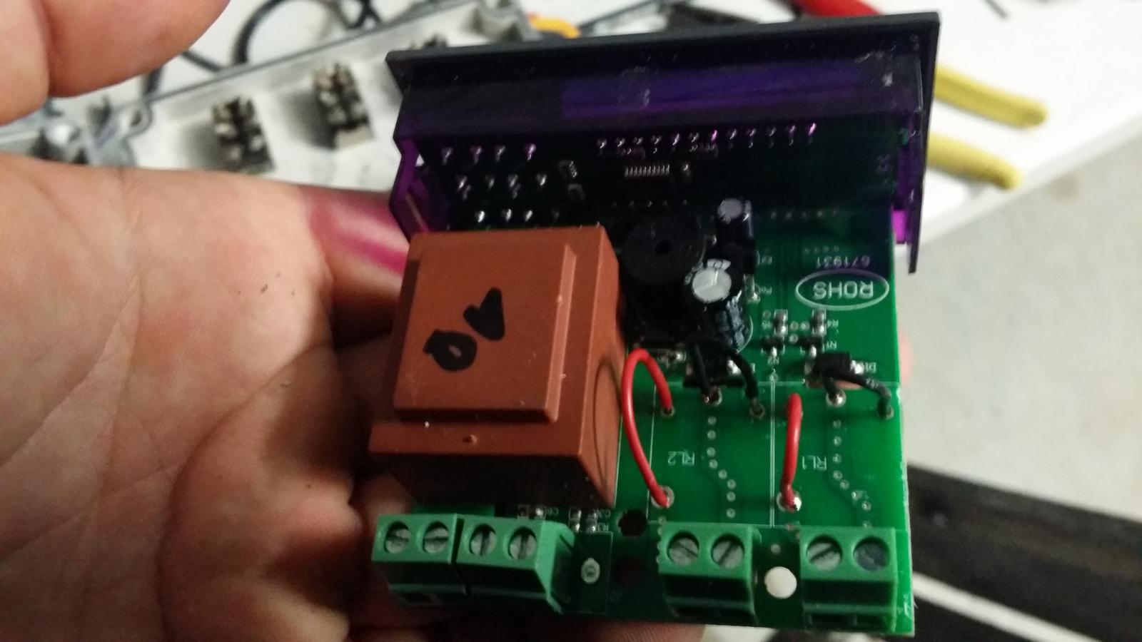
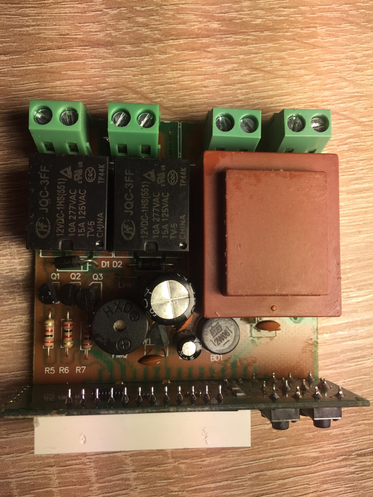
I ordered this from the link on the gitHub page. Took a while but it arrived today. I opened it up and it's a Version1.1 That's the wrong version isn't it? It has the solder points and has A400_P written on it. Is it worth trying? Pic attached.

stcboard.jpg
 
That is the right one. It is the A400_P part that is important. The v1.1 is just the revision of that type of PCB (it got a bit confused before).
So you're good!
 
Hi,

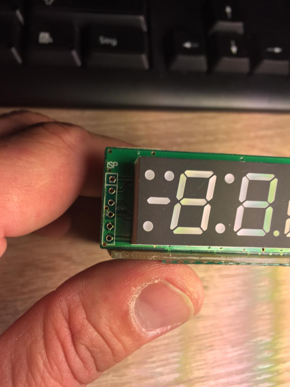
seems like U-CONTROL (the vendor mentioned on GitHub) has changed the layout of the STC. I ordered one there that was ship a few days ago. It has a PIC ISP connect next to the display. Would be perfect....if it works. But it doesn't:(

My Arduino Nana V3.0 gets the sketch. I can connect to the STC and the it say "Check wiring". Looks like the did not just change the layout.

I cannot find any hint to the version. The Chinese contact mailed me _ALL_ products are A400-p version. He/she also mentioned the still use the magic chip that is reprogrammable. Which I doubt now.

I tried to use the standard pinout for PIC ISP connections. If I connect the Arduino to the STC-1000 it make a lot of noise. The noise starts once the 5V pin is connected. Changing the pins by random seems to be dangerous as I might ruin the controller. My electronic knowledge is very limited.....ok....not limited....frankly almost not existing :D

Still staying tuned with the factory to get additional information. Once I know more, I will let you know.

Cheers,

The German Brew Noob

IMG_1958.jpg


IMG_1960.jpg


IMG_1962.jpg
 
That is not an A400_P board (and it does not have the correct MCU). Contact the seller to get it sorted.
 
So I replaced the controller in my eHLT with an STC this weekend with a minute time base flash. One weird thing is that I can’t change the set point for thermostat mode without pulling the power on the whole box. If I'm in thermostat mode, go change the set point, back out and push up arrow it shows the previous temp level. If I then pull the power on the whole box (soft power off won't work) and plug it back in, it start up at the new set point I want. I got the sketch from the editor website.
 
StoneBriar, I am having the same problem. Flashed the minute based code for my cheese making unit and have to unplug from the wall to set any change in the SP. I thought it was my wiring. Good to know. Maybe the experts can pin point the problem.
Tt
 
Glanced over the code, even though I already know why that happens (from your description).
SP is handled differently in minute FW. It is buffered in memory and not written to EEPROM for every change when running a profile to prevent excessive EEPROM wear. But setting a new SP value only updates EEPROM (currently) and not the buffered value. Power cycling fetches the stored value in startup code.
I opened a bug for it, so I won't forget, 'cause right now it's summer :)
Cheers!
 
How do use several firmware on the same unit ? say , 2 sensor, comm, wifi, one vessel, what if you wanted one vessel with comm and wifi? what if you wanted one vessel and 2 sensor?
 
Back
Top