• Please visit and share your knowledge at our sister communities:
  • If you have not, please join our official Homebrewing Facebook Group!

    Homebrewing Facebook Group

Stc-1000+

Homebrew Talk

Help Support Homebrew Talk:

This site may earn a commission from merchant affiliate links, including eBay, Amazon, and others.
I am trying to wrap my head around covering the outputs to 12v so that I can wire it up to an ssr but I'm obviously not getting it completely.

Do you desolder the entire relay off the board and wire up the 12v signal to the points or can you leave the relay there?

Also how are you making the connection? Just with a single strand of dupoint cable?

Is there a decent video that explains all of this?

Sorry in advance for the amateur questions and also if it has been covered before but I'm just not fully understanding the concept.

Cheers
 
You can desolder the relays, or as I did, just buy an SSR that accepts 120v AC as the driving voltage. This is the one I use, but any number of ac-ac SSRs are available for sale.

I am trying to wrap my head around covering the outputs to 12v so that I can wire it up to an ssr but I'm obviously not getting it completely.

Do you desolder the entire relay off the board and wire up the 12v signal to the points or can you leave the relay there?

Also how are you making the connection? Just with a single strand of dupoint cable?

Is there a decent video that explains all of this?

Sorry in advance for the amateur questions and also if it has been covered before but I'm just not fully understanding the concept.

Cheers
 
Last edited by a moderator:
If you are converting to SSR, you must desolder the relays (or the connection will short out when the relay closes) . Then bridge the indicated connections by soldering in a piece of wire.
You also can do what @stoneBriar suggests (leave the relays in place and use AC/AC SSR's), but it sort of leaves you with the drawbacks* of both the mechanical and the solid state relays, but it is easy to do and it works.

As a side note: What I like about removing the relays and modifying for SSR output, is that the STC then no longer needs mains. You can remove (and jumper) the transformer and convert it to a 12v unit (really anywhere from 7-24v). I.e. you can separate high voltage stuff from low voltage control stuff.

* Not quite true, you still get (depending on the SSR) higher current capability and zero cross switching, which is good. The drawback would be that mechanical relays are noisy and that you will have two sets of relays that can fail.
 
I have hit a bit of a wall with changing the unit to 12v output. I have left it with a 240v input but got the relays off the board and bridged it exactly the way that is shown in the wiki. We have continuity over each point but it's not outputting anything. What have I done wrong?

Thank you
 
That is not nearly enough information to troubleshoot.
First of all, is it supposed to output anything? Is the heating or cooling LED lit?
Secondly, how do you measure the output? Thirdly, exactly what have you done so far? A picture or two could help.
If it worked before, and you have made the right connections and have continuity, then it really should work. Note that you need to connect the SSR's inputs correctly (positive and negative terminal), so if it won't work, just switching the leads could help.
 
Ok I'll elaborate a little as I didn't mention much in the original post. I took the relays off the board which were fully functioning before hand. I wired the point together as shown on the website with a bit of thin cable soldered to the board. I have continuity between each point on the board so I believe that it is wired correctly. I turn the unit on and manually set it to output 200% so that it would have a constant 12v output from each heating and cooling circuit. I used a multimeter to verify the voltage which there was none, I even reversed the polarity to see if I had the wiring around the wrong way. I am still not getting any output. I have attached some photos for you to see if it is all wired correctly.

Thank you

20160623_235140.jpg


20160623_235129.jpg
 
The wiring looks about right to me.
I assume then you have set cO to 200, but have you set run mode (rUn) to constant output (Co)? Otherwise there won't be any output (you've only specified what output to use when in constant output mode).

If this is not the issue, then recheck the soldering. Make sure there are no shorts and that you have continuity from both sides of the board (i.e both sides of the solder pads). After that you'd probably need to start measuring before the transistors, making sure you have a signal from the PIC.
 
Yes I had the CO set to 200% so that both of the outputs should have had a reading since both LED's were lit up.

I will try applying more solder this afternoon and if that doesn't work I will try to put the relays back on the board. I don't know how to test the pic so I might need to leave that one alone.

Looks like you missed this:
"but have you set run mode (rUn) to constant output (Co)? Otherwise there won't be any output (you've only specified what output to use when in constant output mode)."
 
Looks like you missed this:
"but have you set run mode (rUn) to constant output (Co)? Otherwise there won't be any output (you've only specified what output to use when in constant output mode)."

Sorry I should have mentioned that I did set it to run mode (rUn) so it should have been outputting 12V.

Both LED's were lit up showing that there should have been an output.
 
Just for a little bit of feedback, I have been able to get it operational now. I'm not really sure how it is working as it isn't outputting a solid 12v when the unit is being run (rUn) in cO mode, it is only outputting around 2-3V but even when the unit isn't outputting then it still reads 2-3V so I'm a little confused as to how it is working but the SSR that I have hooked it up to is receiving the correct signal so it must be working somehow.
 
Good that it is working, but that does not sound right. Is your voltmeter ok?
It really should output around 12-14v when 'on' and close to 0v when 'off'.
 
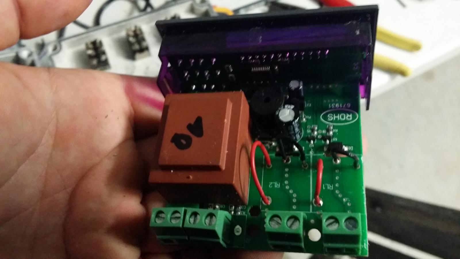
I ordered this from the link on the gitHub page. Took a while but it arrived today. I opened it up and it's a Version1.1 That's the wrong version isn't it? It has the solder points and has A400_P written on it. Is it worth trying? Pic attached.

stcboard.jpg
 
That is the right one. It is the A400_P part that is important. The v1.1 is just the revision of that type of PCB (it got a bit confused before).
So you're good!
 
Hi,

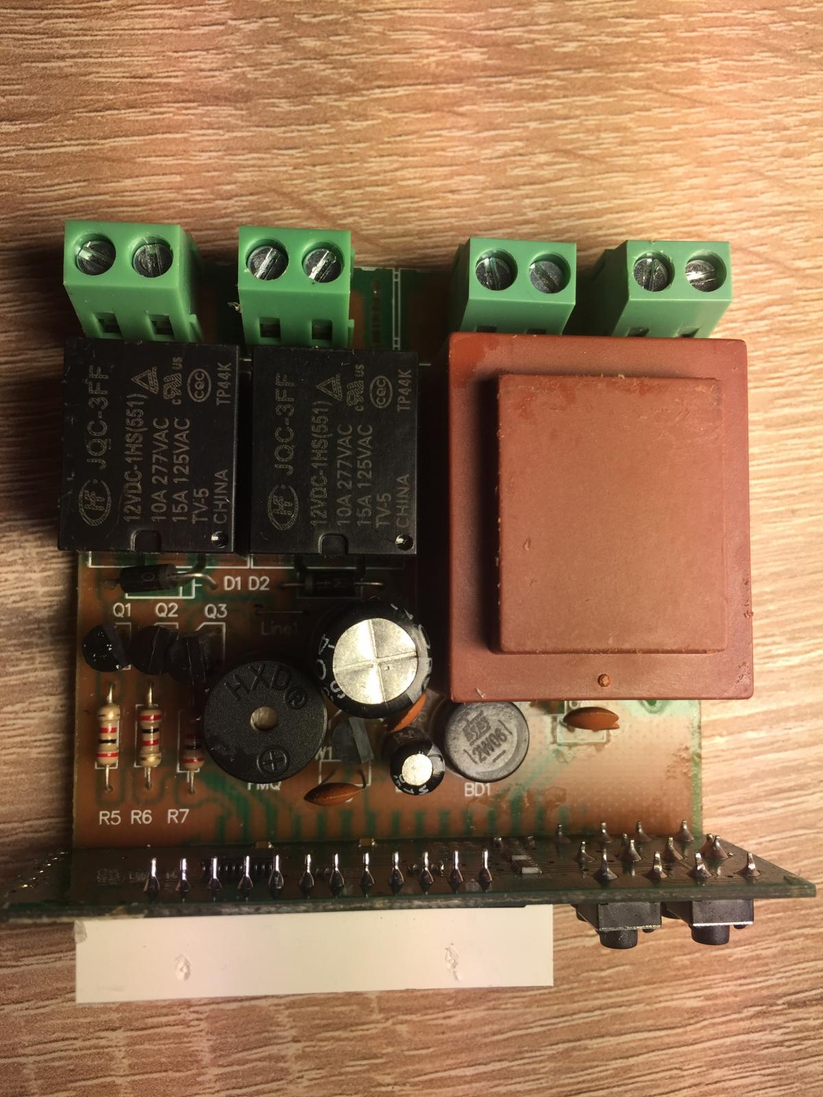
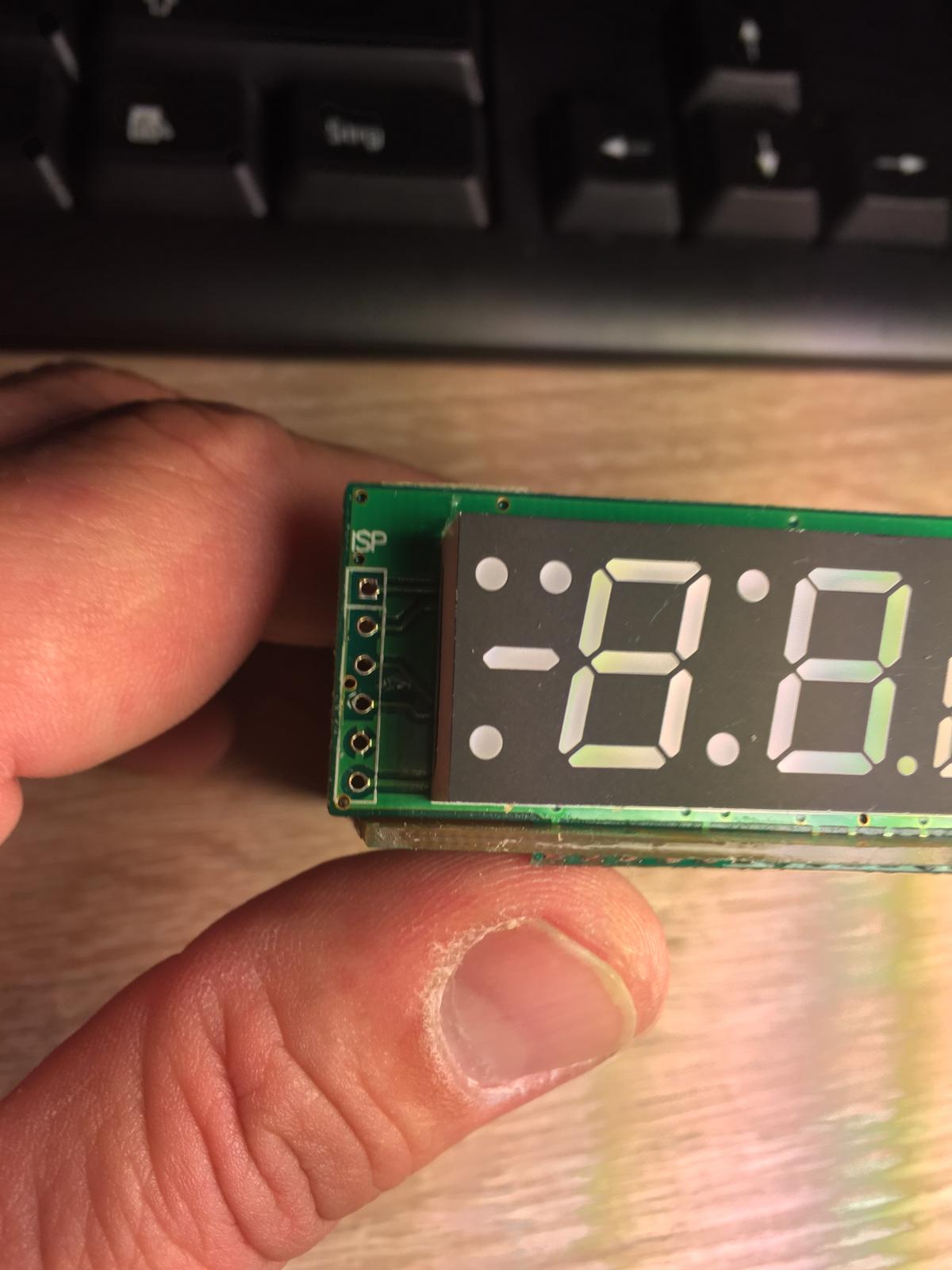
seems like U-CONTROL (the vendor mentioned on GitHub) has changed the layout of the STC. I ordered one there that was ship a few days ago. It has a PIC ISP connect next to the display. Would be perfect....if it works. But it doesn't:(

My Arduino Nana V3.0 gets the sketch. I can connect to the STC and the it say "Check wiring". Looks like the did not just change the layout.

I cannot find any hint to the version. The Chinese contact mailed me _ALL_ products are A400-p version. He/she also mentioned the still use the magic chip that is reprogrammable. Which I doubt now.

I tried to use the standard pinout for PIC ISP connections. If I connect the Arduino to the STC-1000 it make a lot of noise. The noise starts once the 5V pin is connected. Changing the pins by random seems to be dangerous as I might ruin the controller. My electronic knowledge is very limited.....ok....not limited....frankly almost not existing :D

Still staying tuned with the factory to get additional information. Once I know more, I will let you know.

Cheers,

The German Brew Noob

IMG_1958.jpg


IMG_1960.jpg


IMG_1962.jpg
 
That is not an A400_P board (and it does not have the correct MCU). Contact the seller to get it sorted.
 
So I replaced the controller in my eHLT with an STC this weekend with a minute time base flash. One weird thing is that I can’t change the set point for thermostat mode without pulling the power on the whole box. If I'm in thermostat mode, go change the set point, back out and push up arrow it shows the previous temp level. If I then pull the power on the whole box (soft power off won't work) and plug it back in, it start up at the new set point I want. I got the sketch from the editor website.
 
StoneBriar, I am having the same problem. Flashed the minute based code for my cheese making unit and have to unplug from the wall to set any change in the SP. I thought it was my wiring. Good to know. Maybe the experts can pin point the problem.
Tt
 
Glanced over the code, even though I already know why that happens (from your description).
SP is handled differently in minute FW. It is buffered in memory and not written to EEPROM for every change when running a profile to prevent excessive EEPROM wear. But setting a new SP value only updates EEPROM (currently) and not the buffered value. Power cycling fetches the stored value in startup code.
I opened a bug for it, so I won't forget, 'cause right now it's summer :)
Cheers!
 
How do use several firmware on the same unit ? say , 2 sensor, comm, wifi, one vessel, what if you wanted one vessel with comm and wifi? what if you wanted one vessel and 2 sensor?
 
@gillie: 2 sensor FW uses the 'unused' pin to read an extra sensor, com FW uses the pin to communicate with an arduino, OVBSC uses the pin for pump control.
If you want OVBSC but with 2 sensors, all the source code is available (that is, all the *hard* work is already done). So, feel free to modify it to your liking. You're welcome.
 
regarding adding a pump to be controlled by STC ,
the pump has 2 wires in the power lead, positive and negative or positive and ground?
where does wire connect to on the stc circuit board? do you need to install a resistor or a capacitor as well when wiring it in?if you wire the positive wire to "J2" where do you wire the ground wire?
as far as the pump goes, I don't even know if the 2 wires are + and - or if they are + and GND , does anyone know its a12v little brown pump off ebay ?
 
In the OVBSC configuration, does the pump control relay need to be a SSR? I have used a normal relay with a 3VDC coil but it does not switch. The voltage is pulled down from 5VDC to 0,25VDC. Any help will be appreciated.
 
I cant stress enough how amazing this project that alphaomega has created is for small scale homebrewer, was reading about it a lot. And I wanted to jump on the bandwagon and order an STC 1000. Ordered one from eBay as wasn`t too patient to order one from china. Received one Today, and (as always with my bad luck) not the right hardware version that was used - A-400P.

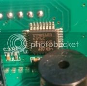
The one I received has STM8s103 microcontroller which seems to be programmable judging from the datasheet.datasheet


The board has connections on the screen that appear to be connections for programming see pictures


My question is would it be possible to adjust the current project to be available for the STM8S103 based microcontrolers?

I know I`m not the only one who would be interested in a solution for this.
Meanwhile will order the correct one from aliexpress.

Thanks in advance guys :)

Tom.
 
@alphaomega

I was using the Hex Editor page a week or so ago for the ferment controller and had no problems. However, at the moment I have tried to download the OVBSC sketch and after I press download it does nothing. I tried on a different computer and when I pressed download it just changed from C to F with each press of the download button.
 
In the OVBSC configuration, does the pump control relay need to be a SSR? I have used a normal relay with a 3VDC coil but it does not switch. The voltage is pulled down from 5VDC to 0,25VDC. Any help will be appreciated.

Got a SSR and it works fine. The controller is fantastic.
 
@stagefever: I think that is the first non A400_P STC-1000 that I've seen that has a 'sane' MCU (documentation and toolwise).
It would require some work, but that hardware at least should be reasonably possible to reprogram.
 
I'm trying to find out more about wiring the pump to the stc any advice and or pics ?
 
Back
Top