Stc-1000+

Homebrew Talk - Beer, Wine, Mead, & Cider Brewing Discussion Forum

Help Support Homebrew Talk - Beer, Wine, Mead, & Cider Brewing Discussion Forum:

This site may earn a commission from merchant affiliate links, including eBay, Amazon, and others.
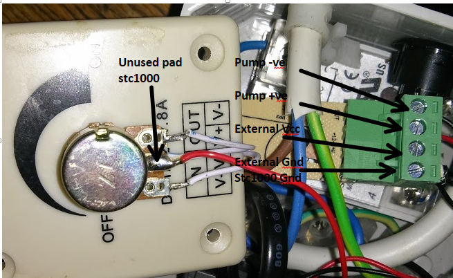
@gillie: 2 sensor FW uses the 'unused' pin to read an extra sensor, com FW uses the pin to communicate with an arduino, OVBSC uses the pin for pump control.
If you want OVBSC but with 2 sensors, all the source code is available (that is, all the *hard* work is already done). So, feel free to modify it to your liking. You're welcome.
 
regarding adding a pump to be controlled by STC ,
the pump has 2 wires in the power lead, positive and negative or positive and ground?
where does wire connect to on the stc circuit board? do you need to install a resistor or a capacitor as well when wiring it in?if you wire the positive wire to "J2" where do you wire the ground wire?
as far as the pump goes, I don't even know if the 2 wires are + and - or if they are + and GND , does anyone know its a12v little brown pump off ebay ?
 
In the OVBSC configuration, does the pump control relay need to be a SSR? I have used a normal relay with a 3VDC coil but it does not switch. The voltage is pulled down from 5VDC to 0,25VDC. Any help will be appreciated.
 
I cant stress enough how amazing this project that alphaomega has created is for small scale homebrewer, was reading about it a lot. And I wanted to jump on the bandwagon and order an STC 1000. Ordered one from eBay as wasn`t too patient to order one from china. Received one Today, and (as always with my bad luck) not the right hardware version that was used - A-400P.

The one I received has STM8s103 microcontroller which seems to be programmable judging from the datasheet.datasheet


The board has connections on the screen that appear to be connections for programming see pictures


My question is would it be possible to adjust the current project to be available for the STM8S103 based microcontrolers?

I know I`m not the only one who would be interested in a solution for this.
Meanwhile will order the correct one from aliexpress.

Thanks in advance guys :)

Tom.
 
@alphaomega

I was using the Hex Editor page a week or so ago for the ferment controller and had no problems. However, at the moment I have tried to download the OVBSC sketch and after I press download it does nothing. I tried on a different computer and when I pressed download it just changed from C to F with each press of the download button.
 
In the OVBSC configuration, does the pump control relay need to be a SSR? I have used a normal relay with a 3VDC coil but it does not switch. The voltage is pulled down from 5VDC to 0,25VDC. Any help will be appreciated.

Got a SSR and it works fine. The controller is fantastic.
 
@stagefever: I think that is the first non A400_P STC-1000 that I've seen that has a 'sane' MCU (documentation and toolwise).
It would require some work, but that hardware at least should be reasonably possible to reprogram.
 
I'm trying to find out more about wiring the pump to the stc any advice and or pics ?
 
@alphaomega

If there is anything I can do to help out, let me know. I have ordered an St ink v2 clone just in case. I'm terrible at C language, haven't really used it since Uni. But yeah, would love to help
 
@stagefever: I've only got A400_P ones and have put a lot of work into getting the software to where it is now. I know where to get more A400_P ones if i should need them. I neither can (since I don't have any of that model) nor do I have much time and interest in porting it.
I'll gladly help out as much as I feel I can, answering questions and such, if someone else wants to port it.

@gillie: Who are you talking to? Me? I gave you the link to where I explain it best I can.
 
I've seen the sketch but I'm unsure of what wire goes where on the board ? seems the only way is to wire it to a dimmer and wire that to the stc ?
 
Hello alphaomega and all others on the forum.
Is it possible to utilize both relays when using the humidify/dehumidify
function of the STC-1000+ firmware?
All humidify controllers out there in the same format seems to use 1 relay
for hum/dehum when all temperature controllers seems to use 2 relays.
alphaomega are you planning in the future to write a firmware that turns
the STC-1000 into hum/dehum PID function?
Maybe the firmware does not have to be as complex as the PID brew firmware but work as the standard hum/dehum controllers out there with the exception that it uses 2 relays instead.
Thanks in advance
Peter
 
@LordCutlerBeckett: The firmware (that I think) you're talking about, does not really aim to control humidity, but rather to keep the environment out of the 'danger zone' where organic growth happens, by enabling heaters to raise the temperature and thereby lowering relative humidity (that is, keeping stuff dry).
It enables both relays if I remember correctly, but both do the same thing.
I have no plans to write a humidity controller, but I'm sure it would be feasible to do and that firmware would probably make a very good starting point. Feel free to do it yourself if you want to!
And it'll be a looong time (and probably a severe case of amnesia) before I attempt to implement a generic PID on the STC again... :)
 
Ok will have a look, actually asm was the only thing I programmed a long time ago with the
pic16c84 and the likes :)
I havent tried arduino or c language really but will start now.
I was thinking maybe use your temperature PID program as template and just replace
heat for humidify and cool for dehumidify and use the spare pin for hum sensor together with the existing ntc sensor or maybe use one of those combined sensors with both hum and temp
that sends a dataword in intervals or some similar.
Anyway thanks for reply
 
Hmm. ok, Then I`m in trouble, since I do host files all the time trough google.
 
anyone know where to get one of the stc a400 p controllers need for this just paid $20 @ ucontrol and they sent a clone ( OR "UPDATED" version). this project looks so promising too. I would prefer a 230 volt version but can adapt a 110 after all the transformer out of the clone must be good for something lol
 
ok I have got everything ready box is ready stc has been up graded all my parts are here . But still unsure how I connect the pump to the unit . can anyone post some pics or step by step ? cheers . Planning to use the stc to run the pump for the mash cycle . Need a bit more detail then the previous posted pages offer .
 
I'm using a 12v pump so SSR not need ? anyone one used a 12v pump with this set up ? Advice on wiring a 12v pump and not a 240v mains pump would be great . All these links are for 240v pumps mains pumps any advice on a 12v pump ? seems silly to make a 20 dollar control to use a 120 dollar pump ? 12v pump working great for 20 bucks of ebay .
 
@gillie: Here's some pictures that might be of help. They show how to use a LED dimmer to drive the pump from the STC.

2jcu6fp.jpg


wpid-wp-1431986371913.png
 
my friends say the dimmer will damage the pump , is it an issue?

That your friend is talking too much? I don't think so, unless make it an issue :)

Seriously though, PWM control of brushed DC motors is very common practice. I really doubt that it will be a problem.
 
anyone know where to get one of the stc a400 p controllers need for this just paid $20 @ ucontrol and they sent a clone ( OR "UPDATED" version). this project looks so promising too. I would prefer a 230 volt version but can adapt a 110 after all the transformer out of the clone must be good for something lol

anyone? please i alrdy bought all the programming gear thinking that i had one coming.
 
Some very good news here!

A very nice and tech whizzy guy from the Netherlands, Emile, has started a new firmware for STC-1000 units boasting the STM8 microprocessor.

34hw8hx.jpg


The project is brand new and currently under active development, but looks very promising! Anyone who got this type of unit (and the slightest interest in modding it to do their brewing bidding), start by ordering an ST-Link programmer (the clones are very cheap on eBay).

st_link_v2.png


The project can be found here: https://github.com/Emile666/stc1000_stm8

Give a round of applause for @Emile666 !!!
 
Thanks man! I was intrigued by your original modification for the STC1000. When I ordered a few units, I noticed that they had other hardware (STM8S microctrontroller). I reverse engineered it and adapted your software to the new hardware. There's still lots of testing to do, but I hope that it is useful for people with this particular hardware version.

As some kind of bonus feature I added a PID-controller to it and used an (unused) output pin at the back of the STC1000 device, so you can control a SSR with it.

Several features Mats had in his original firmware are included by default (e.g. 2nd temperature probe, switchable between Fahrenheit and Celsius, minutes/hours selectable), others are not included yet (the RH and the OVBSC).

Again: I haven't done any rigorous testing, but I will over the next few weeks. Most functions seem to work however.

This is awesome for those who have units they thought they could not flash.

I'm going to have to check my non AP 400 controller to see if I can hack it.
 
I'm going to have to check my non AP 400 controller to see if I can hack it.
The code on top says '0602 05 R QC', the text on the frontpanel PCB says 'WR-032' and the text on the IC says '8S003F3P6'.

It would be nice if more people can confirm that the '0602 05 R QC' label is indeed a unique identifier for this particular hardware version. Makes ordering on ebay / Aliexpress less of a guess.
 
I've ordered one unit from eBay, based on the text on the sticker (and the visibly blue relays through the vents). I'll see what I get in a few weeks.
Sadly, the pictures on eBay/ali are not to be trusted...
 
I made several updates to the README, User-Manual and the source-files. Software works fine, I did a few rounds of testing. I need to do some more testing with the PID controller, but it all seems to work. If you set parameter Ts (new) to a non-zero value (e.g. 20 seconds), you get PID-control instead of thermostat (on-off) control.

I replaced the stock microcontroller on a couple of devices with one that has more eeprom size. Description on how to do this is given in the README file. This works without problems and then you have Mats his version with 6 profiles and up to 9 temperature-time pairs again.
 
Back
Top