
Hello All, I'll be putting together an eHERMS build in my garage and I thought I'd document it here and take advantage of the hive mind. I'll try to do this in some sort of systematic way, but who knows...lol. I've decided to get the bulk of my parts from Brew Hardware and build/use a Brew Buddy 1. I like the set up on it and It's a bit less expensive than a Kal panel... also trying to do this on a budget and put my dollars where it counts.
One of the things I think i need to clarify, at least in my mind, is the electrical connection. I plan on using the dryer receptacle and run an extension cord, with an adapter, to the panel. Lucky enough, it's a 50a breaker. So I think all I need to do is swap out the current breaker with a GFCI unit.
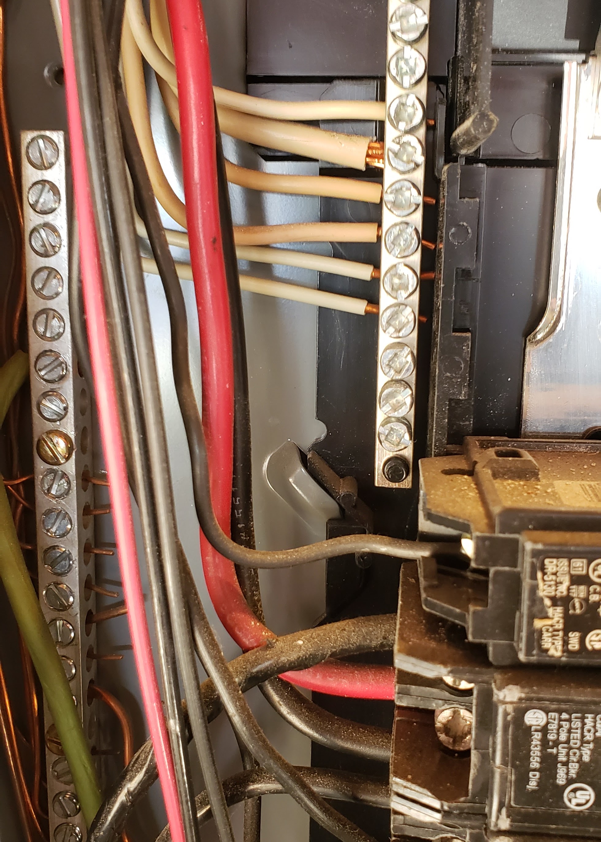
Breaker
Extension Cord
Adapter
Kinda just want to make sure I won't be starting fires and the like when I run the 30a controller on a 50a breaker.
I'll post pictures as I go along too. I'll show you my current space and what I'll be putting where.
One of the things I think i need to clarify, at least in my mind, is the electrical connection. I plan on using the dryer receptacle and run an extension cord, with an adapter, to the panel. Lucky enough, it's a 50a breaker. So I think all I need to do is swap out the current breaker with a GFCI unit.
Breaker
Extension Cord
Adapter
Kinda just want to make sure I won't be starting fires and the like when I run the 30a controller on a 50a breaker.
I'll post pictures as I go along too. I'll show you my current space and what I'll be putting where.


![Craft A Brew - Safale S-04 Dry Yeast - Fermentis - English Ale Dry Yeast - For English and American Ales and Hard Apple Ciders - Ingredients for Home Brewing - Beer Making Supplies - [1 Pack]](https://m.media-amazon.com/images/I/41fVGNh6JfL._SL500_.jpg)


")


