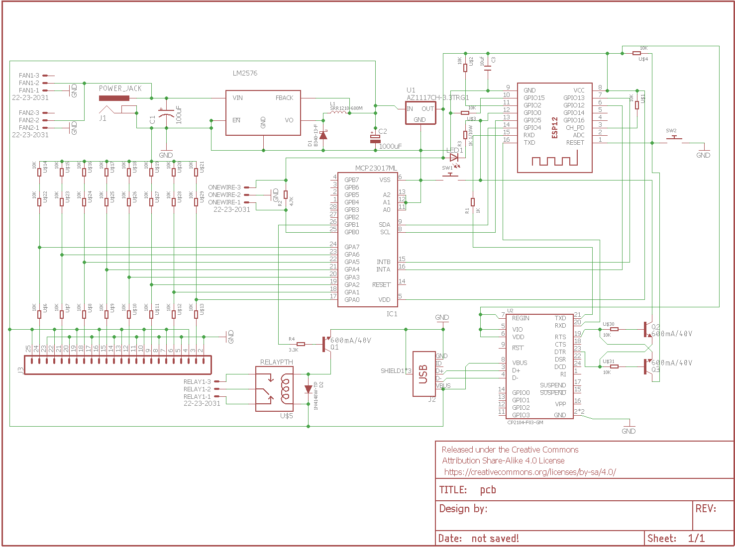
Creating a thread to document my specific build.
Actual build:
https://www.homebrewtalk.com/showthread.php?t=631219
RPints will be installed:
https://www.homebrewtalk.com/showthread.php?t=487694
A version of the Temp display will be added on:
https://www.homebrewtalk.com/showthread.php?t=469523
The goal is to have the tap list and temp sensors displayed on a screen. I currently dont have an interest for graphing or archival data. Maybe later. My goal is to have a Pi that is completely decoupled from the keezer, and not required for basic keezer functionality.
I currently have a NodeMCU 1.0 ESP8266 hooked up to the keezer. I also have an adafruit Huzzah and a couple of ESP32s. I am going to try to get this to work on the ESP8266 and if I cant, move over to the ESP32. I will have 2 temperature sensors (OneWire), 2 Relays (one for fans and one for Compressor) and 6 adafruit flow meters. At the moment I have a little OLED 0.96" screen mainly to help troubleshoot while I work on this. I ultimately would like to build a PCB that can make all this way simpler. Hopefully with connectors for the flow meters and temp sensors.
I am breaking this out because it was/is pretty tough to parse through 300 or so total pages of posts. And if anyone wants to do what I did, there is a concise location.
So first task to to get the ESP to send data to the pi. all 6 pulses and 2 temp readings.


![Craft A Brew - Safale BE-256 Yeast - Fermentis - Belgian Ale Dry Yeast - For Belgian & Strong Ales - Ingredients for Home Brewing - Beer Making Supplies - [3 Pack]](https://m.media-amazon.com/images/I/51bcKEwQmWL._SL500_.jpg)


