Walker, which schematic is the one that will work with the parts you listed for mouser? I'm really keen on making one now that a parts list is readily available. Maybe even two!
")
This is how I build them:
The parts list I gave is not 100% complete in the sense that it does not include a board to put all of the parts on. The one in my panel was built by soldering all of that stuff down to one of these:
Dual General-Purpose IC PC Board - RadioShack.com
But that honestly was a bit of a pain. Tiny connections and wires. I have built several more since then, and I went the cheater route and used a
solderless breadboard to assemble them, which is really handy. (If that link is dead, just search ebay for "solderless breadboard" and you will find more.)
The solderless breadboard allows you to quickly assemble them and you can just cut off a short piece of that board since the circuit only needs a few rows of the thing. You can quickly switch components out if you want/need to.
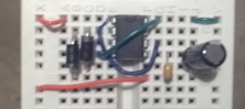
Here's one that is 90% assembled on a solderless breadboard. The only thing not attached is the pot and DC power source which is 5 more wires that need to plug into the board.
edit: if you are looking at this pic to build your own, I had the black capacitor in backwards. There is a grey stripe on the thing to denote which side is the 'negative' side. I have that side pointing up in this above photo, and it should be pointed down. The circuit will NOT work properly if you assemble it like I did here. Turn the large cap around so that the grey stripe is pointing down.
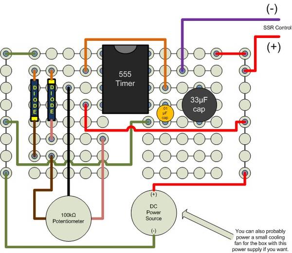
Almost forgot. I drew this pic to help someone assemble one of their own on a solderless breadboard:
The little circles represent the holes in the breadboard and that diagram shows everything connected (power source, pot, all components). It's basically the exact thing I show built above on the breadboard, just with different colored wires.
One thing you may want to add to this is a LED that you can install next to the knob on the panel face. Connect it to the same points that the SSR control signals are connected to. The LED will serve as a visual indicator of the pulse you are generating.
The comment about the fan is on there because the guy I drew this for wanted to add a small CPU cooling fan to his control panel to blow air across his SSR's heatsink, so I was just instructing him to tap the fan into this same DC power source (make sure you use a DC power source that matches the fan in that case.... most cell phone chargers these days are 5V but the CPU cooling fans are often 12V. It'll spin with 5V, but not very fast and won't push enough air to cool well.)


![Craft A Brew - Safale BE-256 Yeast - Fermentis - Belgian Ale Dry Yeast - For Belgian & Strong Ales - Ingredients for Home Brewing - Beer Making Supplies - [3 Pack]](https://m.media-amazon.com/images/I/51bcKEwQmWL._SL500_.jpg)