ClaudiusB
Well-Known Member
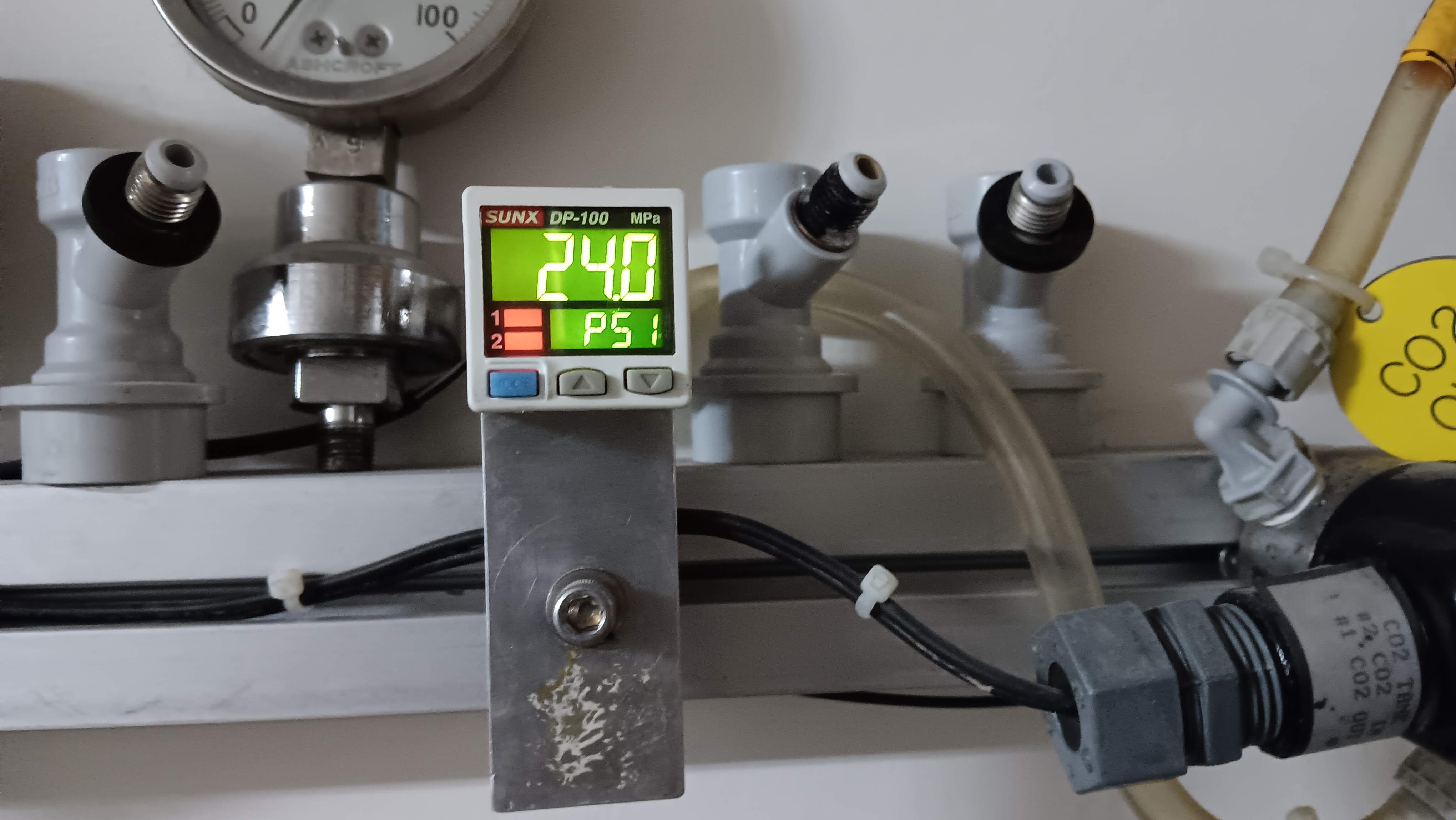
I use a similar pressure sensor for one of my CO2 applications.I've been browsing and wondered if these sensors would also be an option? Quite comprehensive info with the advert, has the added benefit of a display.
https://www.aliexpress.com/item/1005008761403544.html?spm=a2g0o.detail.pcDetailTopMoreOtherSeller.5.6905ZoWhZoWh1z&gps-id=pcDetailTopMoreOtherSeller&scm=1007.14452.396806.0&scm_id=1007.14452.396806.0&scm-url=1007.14452.396806.0&pvid=144f4353-c40a-4daf-b57e-d38bdbffa209&_t=gps-idcDetailTopMoreOtherSeller,scm-url:1007.14452.396806.0,pvid:144f4353-c40a-4daf-b57e-d38bdbffa209,tpp_buckets:668#2846#8109#1935&pdp_ext_f={"order":"32","eval":"1","sceneId":"30050"}&pdp_npi=4@dis!NZD!1.45!1.45!!!6.13!6.13!@2103244617508933126444476e663a!12000046560147677!rec!NZ!1963044316!X&utparam-url=scene
The one you linked only allows you to select the pressure range, omitting other important options such as output type and thread option.


![Craft A Brew - Safale S-04 Dry Yeast - Fermentis - English Ale Dry Yeast - For English and American Ales and Hard Apple Ciders - Ingredients for Home Brewing - Beer Making Supplies - [1 Pack]](https://m.media-amazon.com/images/I/41fVGNh6JfL._SL500_.jpg)