• Please visit and share your knowledge at our sister communities:
  • If you have not, please join our official Homebrewing Facebook Group!

    Homebrewing Facebook Group

possible control panel enclosure?

Homebrew Talk

Help Support Homebrew Talk:

This site may earn a commission from merchant affiliate links, including eBay, Amazon, and others.

HHP

Well-Known Member
Joined
Nov 27, 2010
Messages
374
Reaction score
6
Location
Harker Heights
I am designing my system, which is going to be relatively simple. It is going to be based on the second wiring diagram from this thread: https://www.homebrewtalk.com/f170/simple-eherms-following-pjs-diagram-w-only-1-pid-221403/ although I am going to add an E-Stop circuit similar to Ohio-Ed's.

I also think I would like to have the pumps mounted in the case if possible.

Would this tool box contain everything?
http://www.amazon.com/dp/B003XVMHAE/?tag=skimlinks_replacement-20

I just think it would look sweet to have a briefcase style toolbox control panel for my new brew rig, because I would like rig to be semi-portable.
 
Last edited by a moderator:
To be honest with you, just look on ebay for metal enclosures. You can find them really cheap. I purchased a 12x12x6 that already had a back plate in it. The only problem was there already was a 2" hole cut in the top and I needed to cover it. I got a metal electrical outlet cover and jb welded it to the opening. Then it did have scratched in it so i bought some paint and it looks brand new..

Tool boxes are not water safe. If you get a enclosure make sure it has a splash rating or a gasket.
 
I've got a metal enclosure at home I'll sell you. I think it is 12*12*6. It has some cut outs though. They would fit a PID & switches depending on what size you use.
 
I would rather have a plastic briefcase like this if it will work...

The amazon page says its watertight, and how water tight can anything with holes cut in it, and components mounted be anyways?
 
Should work. Components can be watertight. Look for NEMA ratings on components. NEMA 4 will get you there. NEMA 12 is more of a drip rating.
The plastic might be kinda thick; that might make mounting some things tough. Heat build-up might be worse as well, but not likely a huge problem.
 
I'm sure P-J will be in the thread as well, but if you need help with anything on the diagram or questions feel free to PM me. My panel is completed and housed with my March pump. This was somewhat of a concern with liquid so close, but with pump head mounted vertically and ball valve on output, the chance of wort entering the tool box is very slim. Still thinking of a way to ensure no liquid enters, but I guess thats why we use GFCI.
 
Should work. Components can be watertight. Look for NEMA ratings on components. NEMA 4 will get you there. NEMA 12 is more of a drip rating.
The plastic might be kinda thick; that might make mounting some things tough. Heat build-up might be worse as well, but not likely a huge problem.

Or you can easily solve both problems by crafting an interior panel (you can make it out of aluminum, for example), and mounting the controls to it. That way, there'd be no holes to the case, and it'd be watertight as long as you keep it closed.
 
I'll also add:
I don't claim you need a NEMA rating; I was just saying that it is possible (in response to your question).
 
I'm sure P-J will be in the thread as well, but if you need help with anything on the diagram or questions feel free to PM me. My panel is completed and housed with my March pump. This was somewhat of a concern with liquid so close, but with pump head mounted vertically and ball valve on output, the chance of wort entering the tool box is very slim. Still thinking of a way to ensure no liquid enters, but I guess thats why we use GFCI.
Ha.! I've been watching it since HHP started it. I'll jump in when the concerns turn to the wiring and/or the process function.

Just to weigh in a little, I often recommend the Auberin Instruments - Project Box for this wiring setup. (Squeeky - you know that as I recommended it to you as well.) It's not a water proof box. I have my reasons and recommend it without reservation. It's about the process. Safety is built in with a properly wired & managed rig.

P-J

Good to know P-J, I'll bite.

So I would like to have one pump mounted right away, and possibly later add another pump (just going with one right now for cost reasons).

Now for some basic wiring questions: When I see other peoples rigs they seem to have a raised piece of something, be it plastic or metal that all of their components are mounted to. If this were your project, how exactly would you go about wiring this up?
 
Here is my 12x12x6 metal inclosure. With all the lights and switches I have, 12x12x6 was the worst mistake i made in this build. Everything is very tight, hard to run wires, and i can't expand. I have a SSR which heats up and I wouldn't put it in a plastic box.

Anyone know anything about the auber 2362 PID, I'm having problems with it.

42011 003.JPG
 
I did the auberins box for my build. I was just able to squeeze in the parts for mine with two contactors and two element outlets in the back (one PID and one SSR) and a pump outlet. If you want a box to expand in, the auberins one isn't really the best choice. If you are going one PID and one element it is perfect.

Here is a view into my project box for reference:

https://www.homebrewtalk.com/f170/electric-burners-any-builders-out-there-228720/index25.html
 
Man, it looks really cool but I can't read anything. Is there a way to blow it up. That might help with my build. Are you doing a RIMS?
 
Man, it looks really cool but I can't read anything. Is there a way to blow it up. That might help with my build. Are you doing a RIMS?

Oh you mean the wiring diagram? I am building a herms down the road, with one PID that will support two elements (not at the same time of course).

Trying ot figure out how to get a higher resolution pic posted. I could also email it to you if you PM me.

When I post the file it lowers the resolution, I can send you a JPG or visio file of the end diagram - let me know. Or let me know how to post the higher res file and I will do it.

At the end of the day I put together my final wiring diagram with an alarm, and a power indicator light into the box (but the indicator didn't fit and I have decided to wait on the alarm). I also added a fan with a switch on the right side that blows into the box on my SSR heat sink. Since the auberins box has a vented back, it works great. Blows in to cool the heat sink and vents out the back.
 
P-J

Is it possible to get the afore mentioned schematic drawn up with a relay controlling which element? I really dont like the idea of my hand touching a switch that has 30A 240v running through it...
 
Here is my 12x12x6 metal inclosure. With all the lights and switches I have, 12x12x6 was the worst mistake i made in this build. Everything is very tight, hard to run wires, and i can't expand. I have a SSR which heats up and I wouldn't put it in a plastic box.

Anyone know anything about the auber 2362 PID, I'm having problems with it.

I know whatcha mean. I'll be pretty much completely filling up the front of the enclosure, definitely completely filling up the right side of it, and using about a third of the left side. I will have it much worse than you did, but I know it's do-able.

If you could please post a pic of the interior. I'd like to see how bad it is.
 
P-J

Is it possible to get the afore mentioned schematic drawn up with a relay controlling which element? I really dont like the idea of my hand touching a switch that has 30A 240v running through it...
HHP,

Ok - here is a diagram that uses a DPDT - Center Off switch to control the contactors. The switch has a plastic handle so that it should eliminate the concern. Additionally, I added an EPO switch that is designed to trip the GFCI breaker in the mains panel in the event of an emergency.
(Click on the image to see a ful scale diagram.)


Hope this helps you.
 
I know whatcha mean. I'll be pretty much completely filling up the front of the enclosure, definitely completely filling up the right side of it, and using about a third of the left side. I will have it much worse than you did, but I know it's do-able.

If you could please post a pic of the interior. I'd like to see how bad it is.

I can do that, I just read your post today and I'm at work now. I will take a pick this weekend and try to post if before monday. But, it will most likely be monday when I post it.
 
P-J, much better. My system is different than yours. I am having problems with mine and some of what you show in that diagram may help me out.
 
P-J

Thanks a bunch. I am going to build it just like this, although I may use Ohio-Ed's E-Stop circuit for the sheer bling factor of the on button and the satisfying clunk as the contactor throws...
 
P-J

Thanks a bunch. I am going to build it just like this, although I may use Ohio-Ed's E-Stop circuit for the sheer bling factor of the on button and the satisfying clunk as the contactor throws...


Whats the E-stop?
 
I know whatcha mean. I'll be pretty much completely filling up the front of the enclosure, definitely completely filling up the right side of it, and using about a third of the left side. I will have it much worse than you did, but I know it's do-able.

If you could please post a pic of the interior. I'd like to see how bad it is.

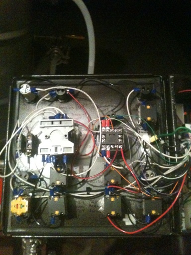
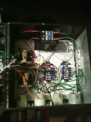
Here are the pics.

5211 007.JPG


5211 008.JPG
 
It doesn't look that bad but trust me, it is. Because it's only 6" deep, the components on the panel make it impossible to add anything else when the door is shut. It makes things really hard to work with as well. Go 8" deep or deeper.
 
It doesn't look that bad but trust me, it is. Because it's only 6" deep, the components on the panel make it impossible to add anything else when the door is shut. It makes things really hard to work with as well. Go 8" deep or deeper.

I was going to say - looks freakin' spacious compared to mine! ;)
 
Trust me, because it's only 6" deep when you shut the door, the components on the door fill up the empty space you see on the inside of the box. There is absolutely no room what-so-ever to add anything else.
 
pola and Cidah, I feel your pain!

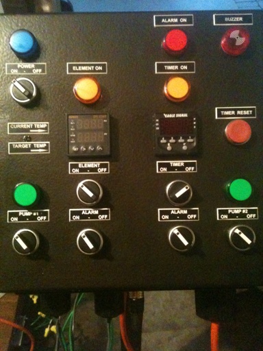
Check out my current control panel and imagine fitting in what I'm about to fit in: I'll be installing 3 PIDs (SYL-2352), 3 SSRs, 4 DPST relays, a 120VAC to 24VAC xfmr, 3 TCs (for the PIDs), a timer (ASL-51), a timer reset button, an alarm indication light, an alarm buzzer, 4 alarms switches, another bus (the 120VAC Hot B Bus), a 4-position switch, and element indication lights (HLT, MLT, and BK), and a brewery label. The PIDs and timer will have to be mounted on the sides!

I know it'll be do-able, though, cuz I measured and calculated it all out. I just gotta make sure the wiring is clean and organized (unlike what it is right now!).
 
good luck with that, seriously. Your heat sinks are going to cause problems unless you mount it on the outside which i recommend.
 
Haha - very cool build

I would recc installing the heat sinks on the outside or venting your box and putting in a fan or two to keep the SSRs cool. One guy on here had a seal box with sinks inside, and his SSR was toasted, he thought from overheating. I ended up installing a fan on my box to blow across the sink and vent out the back.
 
good luck with that, seriously. Your heat sinks are going to cause problems unless you mount it on the outside which i recommend.

One guy on here had a seal box with sinks inside, and his SSR was toasted, he thought from overheating.

I believe you are talking about me here, Cidah.

This is how I fixed it; one blows in, one blows out:

HERMS_fans.jpg
 
Back
Top