• Please visit and share your knowledge at our sister communities:
  • If you have not, please join our official Homebrewing Facebook Group!

    Homebrewing Facebook Group

PID settings on arduino based hlt

Homebrew Talk

Help Support Homebrew Talk:

This site may earn a commission from merchant affiliate links, including eBay, Amazon, and others.
Hey fastTalker,
I never said that PID control isn't suited for heating water, I said I don't think the arduino PID library is very well suited for heating water.
here are my thoughts on the library, I could be wrong.

With the default sample time set to
Code:
    SampleTime = 100;

that would mean using a DS18B20 with a 12 bit resolution the conversion time is about 750mS the Iterm would have 7 increases before D could even get calculated, it gets worse when you put in the time it takes to ramp the temperature of the water. If the rate of rise is 2 deg c / min then that equates to 0.033 deg c / second, the finest resolution for a DS18B20 is 0.0625 degc so that means a measured temperature change every 2 seconds which would allow Iterm to increase 20 times before D would have a value

Code:
void PID::Compute()
{
   if(!inAuto) return;
   unsigned long now = millis();
   unsigned long timeChange = (now - lastTime);
   if(timeChange>=SampleTime)
   {
      /*Compute all the working error variables*/
	  double input = *myInput;
      double error = *mySetpoint - input;
      ITerm+= (ki * error);
      if(ITerm > outMax) ITerm= outMax;
      else if(ITerm < outMin) ITerm= outMin;
      double dInput = (input - lastInput);
 
      /*Compute PID Output*/
      double output = kp * error + ITerm- kd * dInput;
      
	  if(output > outMax) output = outMax;
      else if(output < outMin) output = outMin;
	  *myOutput = output;
	  
      /*Remember some variables for next time*/
      lastInput = input;
      lastTime = now;
   }
}

If I term is there to remove a constant error that persists with a P drive only, which it is, why is it allowed to ramp to 100% of the output? If you had a constant error that required 100% output then your drive system is too small. I believe that for D to really be effective it should be subtracted from I term like this

Code:
ITerm-=(Kd*dInput);
double output = kp * error + ITerm;

that would allow D to stop Iterm from winding up if the rate of change is large enough.

Code:
void PID::SetTunings(double Kp, double Ki, double Kd)
{
   if (Kp<0 || Ki<0 || Kd<0) return;
 
   dispKp = Kp; dispKi = Ki; dispKd = Kd;
   
   double SampleTimeInSec = ((double)SampleTime)/1000;  
   kp = Kp;
   ki = Ki * SampleTimeInSec;
   kd = Kd / SampleTimeInSec;
 
  if(controllerDirection ==REVERSE)
   {
      kp = (0 - kp);
      ki = (0 - ki);
      kd = (0 - kd);
   }
}

The last thing is if you increase the sample time the D gain is reduced and the I gain is increased.
I believe that the PID library would be well suited for fast responding symmetrical drive systems like motors but for heating water it isn't quite right but can be worked around.
Again, these are just my thoughts and I could be wrong as I'm not an expert on PID systems

cheers steve
 
Just caught this thread and wanted to chime in. I haven't yet messed with it but I did find this in line 26 the PID_v1.cpp file of the PID library

Code:
SampleTime = 100;	//default Controller Sample Time is 0.1 seconds

Since for heating large volumes of water there is massively small changes in the I and D calculation over 0.1 seconds of time the Ki and Kd terms need to be high in order to show any effect. For our situation, it might be advisable to change that to 10,000 or at least mess with other orders of magnitudes to get Ki and Kd in line with the process.

edit: and looks like i read through everything except for the last page and Matho was already on the same path.... but again, since the SampleTime term only plays with how Ki and Kd interact with the setpoint, a longer sample time could make the PID library much more effective for our application
 
Hey fastTalker,
I never said that PID control isn't suited for heating water, I said I don't think the arduino PID library is very well suited for heating water.
here are my thoughts on the library, I could be wrong.

With the default sample time set to
Code:
    SampleTime = 100;

Code:
void PID::Compute()
{
   if(!inAuto) return;
   unsigned long now = millis();
   unsigned long timeChange = (now - lastTime);
   if(timeChange>=SampleTime)
   {
      /*Compute all the working error variables*/
	  double input = *myInput;
      double error = *mySetpoint - input;
      ITerm+= (ki * error);
      if(ITerm > outMax) ITerm= outMax;
      else if(ITerm < outMin) ITerm= outMin;
      double dInput = (input - lastInput);
 
      /*Compute PID Output*/
      double output = kp * error + ITerm- kd * dInput;
      
	  if(output > outMax) output = outMax;
      else if(output < outMin) output = outMin;
	  *myOutput = output;
	  
      /*Remember some variables for next time*/
      lastInput = input;
      lastTime = now;
   }
}

If I term is there to remove a constant error that persists with a P drive only, which it is, why is it allowed to ramp to 100% of the output? If you had a constant error that required 100% output then your drive system is too small. I believe that for D to really be effective it should be subtracted from I term like this

Code:
ITerm-=(Kd*dInput);
double output = kp * error + ITerm;

cheers steve

Ok First im by no means an expert on PIDs as I recently just started learning, but there are a few things about your statements that are off.

First with the setpoint, that is the default setpoint, the library has a function to change it, which when libraries include functions like that, its because they can/should be changed to meet your needs. obviously this guy wasnt making this for brewing when he made this so his default isnt going to be what we need. To fix this call:
Code:
myPID.setSampleTime(5000)
and put in what you want for the delay, im going to initially test this with a 5 second delay as not much changes over 5 seconds with 5+gallons of water, you could probably do 10 and be fine.

Second your second point with the I input isnt correct, not the PID part but how he does it. If you compare your code

Code:
ITerm-=(Kd*dInput);
double output = kp * error + ITerm;

with the one provided

Code:
ITerm+= (ki * error);
      if(ITerm > outMax) ITerm= outMax;
      else if(ITerm < outMin) ITerm= outMin;
      double dInput = (input - lastInput);
 
      /*Compute PID Output*/
      double output = kp * error + ITerm- kd * dInput;

You see that the kd*dInput is included further down.

Again Im not an expert on PIDs and know little on them, however, I do know code very well.

A library is a base for the general use of the feature. It is not all powerful and cant be designed for every case. PIDs are used for tons of different situations so it would be impossible to make a library that requires no changes to work for everything. Tons of people have been using this PID for sous vide applications and have gotten great results, Im pretty sure it works for mashing as well.
 
Hi

Be very carefull with the term PID. Around this froum it gets used to describe *any* digital process control. When you look into what is actually being done, well over 90% of the controlls are setpoint rather than PID.

To be very clear, A setpoint is a PID with no I =0 and D=0. To be properly called a PID both terms need to be non-zero. You can have PI controllers (pretty common), or PD controllers (pretty rare) as well as PID's and set points.

Bob
Be very careful reading threads. Most ones on the subject of a PID library, well over 90%, are actually talking about software. In fact, to be called a PID library, the code would actually have to be software.

These guys are just trying to determine how to hack a PID library to make it work for homebrewing.

Hi

If one is trying to make sense out of a control system, it might be a good idea to understand the nomenclature involved before digging into it. By far the majority of people around here are *not* actually using a PID. That's not going to make things any easier to understand.

Bob
 
Hi

If one is trying to make sense out of a control system, it might be a good idea to understand the nomenclature involved before digging into it. By far the majority of people around here are *not* actually using a PID. That's not going to make things any easier to understand.

Bob

By far the majority of people around here are *not* actually using a PID.
Exactly- they are using a PID library. That is why offering a simple solution, like appropriate time constants or I and D gain values is preferable to confusing the issue with even more technical jargon. Your input would have been relevant if you had supplied P, PI, and PD libraries, since there probably aren't any given that the PID library is easily configured to revert to those modes using environment variables, parameters, constants, etc.

They just want it to work, and if they want to know more, it is better to give an appropriate link, as was done earlier in the thread, with more complete explanations.
 
Hey fastTalker,
I never said that PID control isn't suited for heating water, I said I don't think the arduino PID library is very well suited for heating water.
here are my thoughts on the library, I could be wrong.

With the default sample time set to
Code:
    SampleTime = 100;

that would mean using a DS18B20 with a 12 bit resolution the conversion time is about 750mS the Iterm would have 7 increases before D could even get calculated, it gets worse when you put in the time it takes to ramp the temperature of the water. If the rate of rise is 2 deg c / min then that equates to 0.033 deg c / second, the finest resolution for a DS18B20 is 0.0625 degc so that means a measured temperature change every 2 seconds which would allow Iterm to increase 20 times before D would have a value
If I understand what you are saying, then I have to disagree. The integration logic is taking the sample time into account. The smaller the sample time the, the smaller the increase of the I term of the equation every update of the PID. You will integrate more accurately the faster you update the PID output. If you are familiar with calculus then this should be very fundamental.

The I term and the D term calculations use the update time to correctly calculate the rate of change. Notice in the SetTunings() function these lines:
Code:
   ki = Ki * SampleTimeInSec;
   kd = Kd / SampleTimeInSec;
It is calculating instantaneous derivative. Technically, it would be more accurate to use the ACTUAL update time rather than the target update time. However, it will probably be close enough. You should make sure that your Arduino scan time is significantly faster than your PID update time though.

If I term is there to remove a constant error that persists with a P drive only, which it is, why is it allowed to ramp to 100% of the output? If you had a constant error that required 100% output then your drive system is too small. I believe that for D to really be effective it should be subtracted from I term like this

Code:
ITerm-=(Kd*dInput);
double output = kp * error + ITerm;

that would allow D to stop Iterm from winding up if the rate of change is large enough.
In the PIDs most basic form there is no limit to what each of the three terms can contribute to the output. So you limit the I term to keep the PID from winding up so high that the P and D have no effect on the output. This would allow you to have an I only controller if you wanted. The constant error you are referring to is the STEADY-STATE error you get with a P only controller.
And, unless I'm missing something here, isn't that what it is already doing.

There is no reason to update the controller slower. If you are capable of updating the controller faster, you should.

It seems you are over complicating this. A PID updates the output based on:
P - your error now
I - how long you have had error
D - how fast your error is changing

If it's not working change your gains, not the controller.

On another note, I don't agree with how the auto-tune functionality works. Closed-loop tuning is hard to do automatically. It would probably produce better results if it attempted to do an open-loop step change test to measure the first-order lag and dead-time.
 
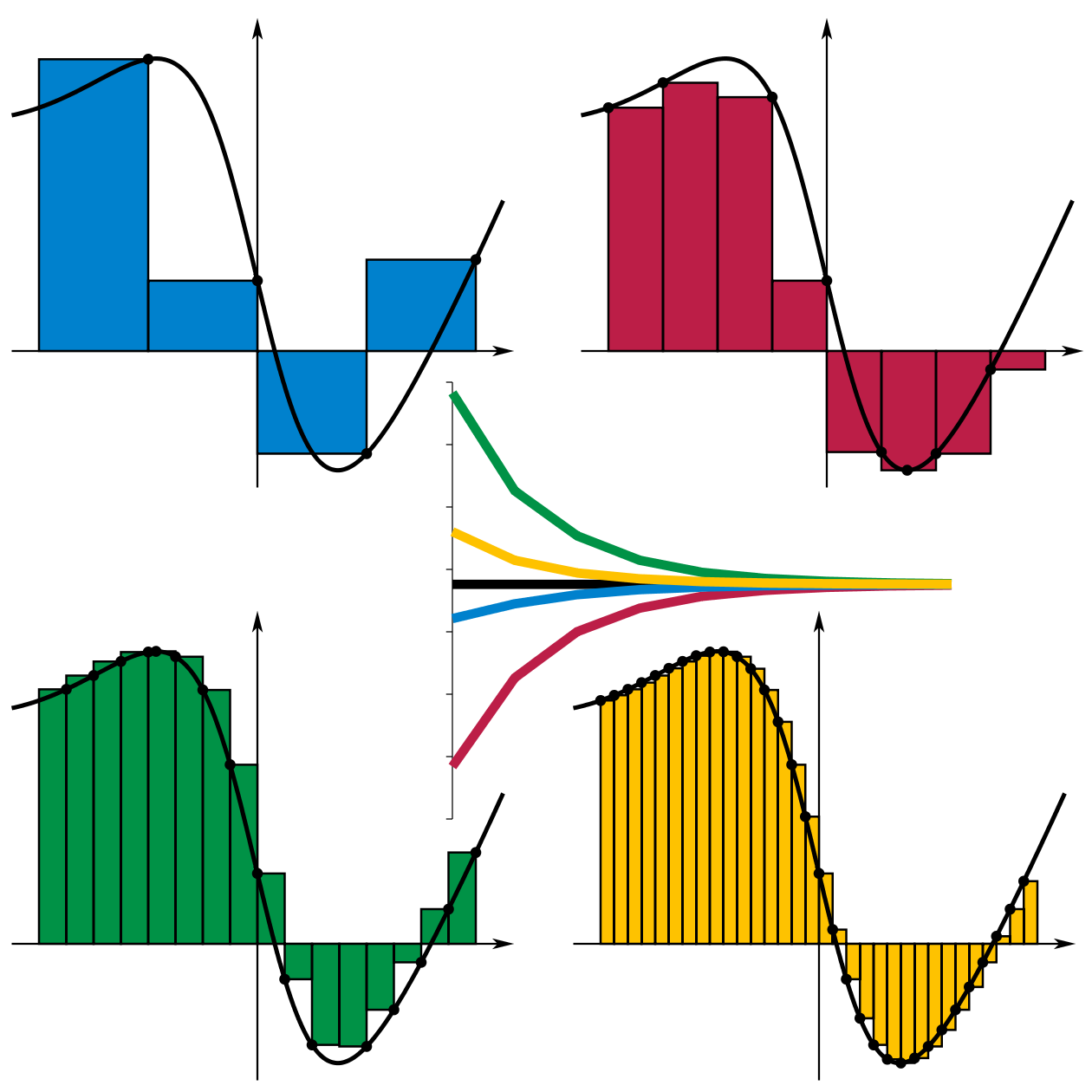
BTW, here's a good visual for showing how accuracy of integration increases with decreased interval size:
http://en.wikipedia.org/wiki/Integral#Riemann_integral
http://en.wikipedia.org/wiki/File:Riemann_sum_convergence.png
Riemann_sum_convergence.png
 
..... It would probably produce better results if it attempted to do an open-loop step change test to measure the first-order lag and dead-time.

Hi

...and possibly consider how to improve (reduce) the lag and dead time before you spend a lot of effort on tuning things. In some systems it's easier to generate a known impulse (short duration power on) rather than a step. Either an impulse or a step can be used to get the basic lag and gain information you need.

Lag = how long before it got moving.
Gain = how much did you make it move with that input

Bob
Are you suggesting a software fix, which is the subject of this thread, to improve/reduce lag time?

As far as I know, most people already have their HLT heating element fully submersed, so physical changes like increasing the element size/number, or agitating to increase transfer are about all that is left to improve lag/gain.

Hi

I'm suggesting that before you spend considerable time playing with step response plots that it's worth looking at your physical setup and seeing if it can be optimized. The optimization will indeed be constrained by the lag you have.

Bob
 
Hi

I'm suggesting that before you spend considerable time playing with step response plots that it's worth looking at your physical setup and seeing if it can be optimized. The optimization will indeed be constrained by the lag you have.

Bob

That is quite interesting, considering your approach to keezer temp control where you advocate the 'probe on cooling coil' method which requires considerably more tuning than the 'probe on keg' method which has been optimized physically.

RE: the issue at hand- besides increasing the number or size of heating elements (usually not an option) or adding agitation like I mentioned previously, do you have any specific ideas other than to 'make it physically perfect' before tuning the loop?

Hi

Sticking to one thing at a time:

The closer the sensor is to the heat source the quicker it will respond. You can indeed move your sensor. In some systems the flow rate through the heat system will impact the lag. There are likely to be multiple limitations on flow rate, so you may not be able to fiddle it as much.

Bob

That makes absolutely no sense. Moving the sensor closer to the corrective input only serves to increase cycling (for on/off systems) and lag (of the entire system for all types). Knowing how quickly the element is heating up doesn't do a lot of good. There is no reason to include the temp of the corrective input into the control loop of an HLT. Maybe for a RIMS tube or MLT where you don't want any localized overheating.

What flow rates are you talking about? I assume the HLT being talked about is using a submersed resistive heating element. General agitation/circulation is beneficial to improve transfer and therefore lag and gain.

This isn't that difficult. The issue is the PID library being discussed was not designed with such a slow responding system in mind. Some of the Auber PIDs come with different algorithms, logic, and parameter baselines specifically for brewing applications.

Personally, I think that on/off, or proportional if you want temps tighter than an on/off controller will provide, is more than sufficient for an HLT. Using gas, I do both, with a manual flame adjustment to get close, plus an on/off control. Adding some kind of circulation system is much more beneficial than trying to PID it. There is significant stratification in an HLT when heated either by direct fire or a submersed heating element. The heating time is also significantly reduced. A bubbler pump is the simplest solution, especially if you already have an aquarium pump for aeration, or from before you upgraded to pure O2.
 
I got a arduino controlled hlt with 1500w element heating like 5 gal.

I overshoot my setpoint by about 10 F.

The integral is too slow to shut the element off once it get to the setpoint

My process class are far away and I don't have a lot of time with the kid to test differents settings.

What are your PID settings on setup like mine ?

The programming of the Ardunio PID library is very typical for a PID controller. It should work just fine for this application.

To get back to the OP, try adding derivative gain. This can help prevent overshoot as it attempts to slow down the rate of change of your temperature. Higher proportional gain can help to provide a similar result since it will decrease as you approach your setpoint. However, too high of a proportional gain can cause oscillation.

Tuning PIDs takes experience, especially for slow loops. And if you don't have a method for trending your temperature and controller output it can be hard to see which gains to adjust.
 
Anybody who is using this library have some example code and how they are wiring this. Ive been working on this, but dont have the hardware to test what I have yet. Got some questions about how to use it:

1. Are you using the PWM digital outputs
2. If not are you using the code like in the RelayOutput example

Is there a way to simulate the code for testing?

I wouldn't recommend using the PWM digital outputs if you are planning on using the PID library. I believe the point of using PWM is to manually adjust your water temperature by increasing/decreasing the duty cycle of the heating element. The PID library should do this for you if your PID constants are set correctly. I plan on setting these constants manually based on how one would tune a regular PID controller. From what I've read, people generally have problems with the Arduino PID Autotune library (at least for brewing applications). Check this thread for some sample code that Chuck dropped in, minus the autotune stuff. Also, I think Chuck posted a thread about a setup where you can switch between the Arduino and a PWM board he created.

I'm still brainstorming the simulation portion of this project.
 
The Arduino's analogWrite(ssrPin,XXX); for PWM is not useful for our purpose. Most of us are using zero-crossing SSR's, which only happens 120 times a second.

Yes, use the relay example from the Arduino site, it works great once you have acceptable values for P, I & D. That is the part that I think most of us find burdensome.

Regarding my PWM board, sure you could use it behind an Arduino, but I can't think of a good reason to do so. If you've got an Arduino, just use the Arduino. The "brain" on my PWM is just the $1.50, tiny version of the chip that's on the Arduino already. It's only useful as a stand alone PWM, or in conjunction w/ a "normal" PID (see Auber, eBay) that does not have a manual mode.
 
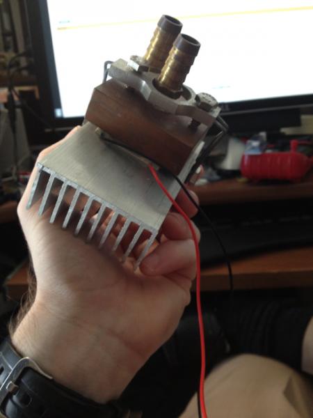
Oh, and for testing, I couldn't figure out a way to simulate, so I built a low-power model to play with.

I clamped a peltier junction between an ancient CPU waterblock and a chunk of aluminum heatsink, using the arduino to drive a MOSFET. It's crude, but worked to prove the code and everything before I moved up to the 115v crockpot.

image-2806068896.jpg
 
It just occurred to me that I never actually shared this part of the code:
FWIW, my settings are: 102.89, 0.5, 0.0.

Also, I think some of my changes have made the constrain line irrelevant, but it's also not hurting anything so I didn't take it out.

Code:
  if (mode ==0)
  {
    //compute output
    byte Course=8;
    byte Fine=2;

    if (Input<(Setpoint-Course)) Output=WindowSize;                                                                       
    //Output is 100% until within Course degrees of setpoint

    else if ((Input>=Setpoint-Course)&&(Input<Setpoint-Fine)) Output=(((Setpoint-Input)/Course)*WindowSize);    
    //This starts reducing power at Course degrees away from
    //the setpoint, so that the temperature is closer to stable before the PID takes over

    else if ((Input>=Setpoint-Fine)&&(Input<Setpoint+Fine))  myPID.Compute();    
    //use the PID library to determine an Output, 
    //if temp is in the fine control band

    else if (Input>=Setpoint+Fine) Output=0;                                                                                    
    //a killswitch in case overshoot gets out of hand

    Output = constrain(Output,0,WindowSize);
    //To elimate the possibility of the greater-than-WindowSize 
    //Output from the offset in the Course band

    OutputPercent = 100*Output/WindowSize;
    if ((millis()-markTime)>WindowSize) markTime=millis();
    if ((millis()-markTime)<Output) digitalWrite(RelayPin,HIGH);
    if ((millis()-markTime)>Output) digitalWrite(RelayPin,LOW);
  }
 
What your are doing is fuzzy logic.
Your choosing a list of criteria that seem logical to your setup.
With the kid I didn't get the time to play with my PID.

Your solution is actually the best result I saw from an arduino control. And it don't go over you setpoint, that is the important part for us brewer as we can heat fast but it take an hour to loose one degre.

But it could be better, you seem to begin to reduce the output too soon.
To find when you should start cutting on the output, start the log, heat 100% from ~120 to ~150 and stop heating, look how far from 150 you go after and that's should be a little over the point where you should start cutting on the heat.

That should reduce your heating time, and that the second most important thing in homebrewing.

By reading all your reply to my post, I understand that the autotune lib is using Z-N in close loop, so basicly raising the gain until the system oscillate. That is a tuning method for pretty fast lineard system.

Our systems are far from linear. And normal system have use for pid as it will stop changing the output at point where the temp doesn't even move anymore. Our system need the temp bascilly turned off when we reach the setpoint.

I think I'll try to use someting like you code as it's now what make the more sens to me.

I'll let you know, just give some time, again.
 
I wouldn't call this fuzzy logic. This is just a piecewise algorithm. Fuzzy logic would implement something like a piecewise algorithm based on the weighted distribution of multiple inputs. You would have to take into consideration not just how far you are from the setpoint but also how fast the input is changing and what the current integral error is. Depending on how you weight each of those you would choose a different algorithm to maintain optimal control. Therefore with fuzzy logic you would have multiple instances where you are X degrees from the setpoint but you may do different things based on how fast the input is changing, etc.

chuckjaxfl said:
if ((millis()-markTime)<Output) digitalWrite(RelayPin,HIGH);
if ((millis()-markTime)>Output) digitalWrite(RelayPin,LOW);
}

One more thing. The above code isn't as efficient as it could be and also contains a corner case. If millis- markTime == Output nothing happens. DigitalWrite doesn't get called in that corner case and the pin will retain its previous state. It's not a big deal as it only happens for one ms, but it could be written more cleanly and efficiently.

if ((millis()-markTime)<Output) { digitalWrite(RelayPin,HIGH);
} else {
digitalWrite(RelayPin,LOW);
}
 
Seems like a really sensible algorithm (cooling and heating *are* asymmetric) and the results look great.
 
But it could be better, you seem to begin to reduce the output too soon.

You would think so, wouldn't you? However, I did some tests setting "coarse" to 6 and 7. In my system, I need to back off at 8. Any more, and I start to overshoot.

To find when you should start cutting on the output, start the log, heat 100% from ~120 to ~150 and stop heating, look how far from 150 you go after and that's should be a little over the point where you should start cutting on the heat.

Which is exactly what I did first. Then I took a day, basically, just trial-and-error all day long with different settings. With the code written as it is now, though, someone else could take it and do it much quicker. Start with ambient temp water, set the temp to 100 and watch the curve. Adjust the two variables, upload the sketch, and set it for 110. Repeat until you're happy, or the pot is boiling.

I think I'll try to use someting like you code as it's now what make the more sens to me.

I'll let you know, just give some time, again.

Please let me know, if you end up using it. It took me a long time to figure out what I *should* have learned by reading mathos' sketch back at the beginning. I just didn't know enough to make use of the information right in front of me.


One more thing. The above code isn't as efficient as it could be and also contains a corner case.

Oops.. you got me!

I actually noted that after reading some other tutorials, but didn't change the sketch on this machine. I was working on that sketch on the laptop out in the garage. The code actually, finally, (I think) wound up as:

Code:
if ((millis()-markTime)>WindowSize) markTime=millis();
if ((millis()-markTime)<=Output) digitalWrite(RelayPin,HIGH);
else digitalWrite(RelayPin,LOW);
 
Hey all,

Just wanted to post some info about my Arduino based PID controller that I've been working on. The Arduino is controlled by an old laptop running a Python GUI that I made for pump controls and for setting a target temperature. I decided not to use the autotune library after reading some of the comments in this thread. I'm going to set my constants through trial and error like I would with an off the shelf PID controller. I tested the control loop a few times by duct taping my temperature probes to a fermentation heat belt. I used DS18b20 temperature sensors and they attach to my controller box via DB9 connectors.

Here's the Arduino code. Ignore the PID settings, since I plan to tweak those as I learn more from my data:
Code:
/* jbrewduino */
/* Developed by Jordan Kagan */ 

// This Arduino sketch reads serves 3 purposes:
// 1. Toggle On/Off a HLT recirculation pump 
// 2. Toggle On/Off a Mash recirculation + sparge pump
// 3. Read input from DS18B20 "1-Wire" digital temperature sensors 
// and control attached heating element based on temperature feed back.
// This will be accomplished via a PID control loop.

// Valid messages are as follows from the Python program:
// "1" means toggle pump 1 off/on
// "2" means toggle pump 2 off/on
// "3" means toggle heating element off/on
// Codes 80 - 212 are reserved for fahrenheit temperatures
//#define DEBUGG
// All inputs are provided by a Python brewing GUI that transmits serial messages.
#include <Time.h>
#include <Wire.h>
#include <PID_v1.h>
#include <OneWire.h> /* for reading 1-wire bytes */
#include <DallasTemperature.h> /* For parsing and printing temp from DS18B20 bytes */
#ifdef HAVE_SD
#include <SD.h>
#endif
// Data wire is plugged into pin 3 on the Arduino
#define ONE_WIRE_BUS 3

// Setup a oneWire instance to communicate with any OneWire devices
OneWire oneWire(ONE_WIRE_BUS);

// Pass our oneWire reference to Dallas Temperature. 
DallasTemperature sensors(&oneWire);
#ifdef HAVE_SD
File dataFile;
char filename[40];
#endif
// Assign the addresses of your 1-Wire temp sensors.

DeviceAddress mashTemp = { 0x28, 0x9E, 0xAC, 0x08, 0x04, 0x00, 0x00, 0x2C };
DeviceAddress hltTemp = { 0x28, 0xFB, 0x1E, 0x15, 0x04, 0x00, 0x00, 0x6D };
String inputString = ""; /* input with temperature from Python GUI */
int newTarget = 0;
int first_write = 0;
int temp = 0;
int bytesSent = 0;
const int heatingPin = 6; /* pin in which the heating element is attached - PID output pin */
int tempLoop = 0; /* This is a global run flag for the temperature feedback loop */
/* We need a valid temperature string because we can also receive messages for toggling 
 * the heating elements and pumps */
int validTemp = 0; 
// On the Ethernet Shield, CS is pin 4. Note that even if it's not
// used as the CS pin, the hardware CS pin (10 on most Arduino boards,
// 53 on the Mega) must be left as an output or the SD library
// functions will not work.
#ifdef HAVE_SD
const int chipSelect = 4;
#endif
//PID Constants
int k_prop = 500;
int k_int = 0;
int k_dif = 0;

double Setpoint, Input, Output; /* PID variables */

//Specify the links and initial tuning parameters
PID myPID(&Input, &Output, &Setpoint,k_prop,k_int,k_dif, DIRECT);
int WindowSize = 1000; /* PID adjusts output between 0 and this window size*/

unsigned long windowStartTime;
unsigned long file_start;

//pumps
const int pumpOne = 5;
const int pumpTwo = 7;
int pumpOneOn = 0;
int pumpTwoOn = 0;

void setup(void)
{
  
  
  pinMode(heatingPin, OUTPUT);
  pinMode(pumpOne, OUTPUT);
  pinMode(pumpTwo, OUTPUT); 
  // start serial port
  Serial.begin(9600);
  while (!Serial) {
    ; // wait for serial port to connect. Needed for Leonardo only
  }
  
  // Start up the library
  sensors.begin();
  // set the resolution to 10 bit (good enough?)
  sensors.setResolution(mashTemp, 10);
  sensors.setResolution(hltTemp, 10);
  inputString.reserve(30);
  
  //Serial.print("Initializing SD card...");
  // make sure that the default chip select pin is set to
  // output, even if you don't use it:
  pinMode(10, OUTPUT);
  
  // see if the card is present and can be initialized:
#ifdef HAVE_SD  
  if (!SD.begin(chipSelect)) {
    //Serial.println("Card failed, or not present");
    // don't do anything more:
    return;
  }
#endif
  //Serial.println("card initialized.");

  windowStartTime = millis();
 
}

/* function that prints temperatures in human readable form */
void printTemperature(DeviceAddress deviceAddress)
{
  if(first_write == 0) {
    file_start = millis();
    first_write = 1;
  }
  float tempC = sensors.getTempC(deviceAddress);
  
  if (tempC == -127.00) {
    Serial.print("Error getting temperature");
  } else {
    //Serial.print("C: ");
    //Serial.print(tempC);
      Input = DallasTemperature::toFahrenheit(tempC);

    if (deviceAddress == mashTemp){
#ifdef HAVE_SD
      dataFile.print("MASH");
#endif
#ifdef DEBUGG
      Serial.print("m");
      Serial.print(Input);
      Serial.print("\n");
#endif
      bytesSent = Serial.write("m");
      bytesSent += Serial.write(Serial.print(Input, 2));
      bytesSent += Serial.write("\n");
    }
    if (deviceAddress == hltTemp) {
#ifdef HAVE_SD
      dataFile.print("HLT");
#endif
#ifdef DEBUGG
      Serial.print("h");
      Serial.print(Input);
      Serial.print("\n");
#endif
      bytesSent += Serial.write("h");
      bytesSent += Serial.write(Serial.print(Input,2));
      bytesSent += Serial.write("\n");
      
    }
#ifdef HAVE_SD
    dataFile.print(",");
    dataFile.print(Input);
    dataFile.print(",");
    dataFile.print(millis() - file_start);
    dataFile.print(",");
    dataFile.println(Output);
#endif
  }
}

void temperatureControl(){
  sensors.requestTemperatures();
  //Serial.print("HLT temperature is: ");
  printTemperature(hltTemp);  
 
      
  //Serial.print("Mash temperature is: ");
  printTemperature(mashTemp); 
  
  myPID.Compute();/* This must be called once per loop to compute the new output*/
  /************************************************
   * turn the output pin on/off based on pid output
   ************************************************/
  if(millis() - windowStartTime>WindowSize)
  { //time to shift the Relay Window
    windowStartTime += WindowSize;
  }
  if(Output > millis() - windowStartTime) {
#ifdef DEBUGG    
    Serial.println("turning heating element ON");
#endif
    Serial.write("HE1");
    Serial.write("\n");
    digitalWrite(heatingPin,HIGH); 
  }
  else {
#ifdef DEBUGG
    Serial.println("turning heating element OFF");
#endif
    Serial.write("HE0");
    Serial.write("\n");
    digitalWrite(heatingPin,LOW); 
    
    //Serial.println("turning heating element off");
  }
  
}

/*Loop that receives input temperature from Python program */
void receiveInput() {
  
  while (Serial.available() > 0) {
    /* once we have input we can start temp control loop */
    tempLoop = 1;
    // get the new byte
    char inChar = (char)Serial.read(); 
    // add it to the inputString:
    inputString += inChar;
    // if the incoming character is a newline, set a flag
    // so the main loop can do something about it:
    if (inChar == '\n') {
      //Serial.println(inputString); 
      newTarget = inputString.toInt();
      if (newTarget > 60 && newTarget < 215) {
#ifdef HAVE_SD
        if(dataFile) {
          dataFile.close();
        }
        sprintf(filename, "LOG-%02d%02d.csv", hour(), minute(), second());
        //Serial.println(filename);
        dataFile = SD.open(filename, FILE_WRITE);
        if(dataFile) {
          //Serial.println("New file opened successfully!");
          dataFile.print("kp = ");
          dataFile.print(k_prop);
          dataFile.print(", ki = ");
          dataFile.print(k_int);
          dataFile.print(", kd = ");
          dataFile.print(k_dif);
          
        } else {
          //Serial.println("Issue opening file..."); 
        }
#endif
        validTemp = 1;
        Setpoint = newTarget;
#ifdef HAVE_SD
        dataFile.print(", SP = ");
        dataFile.println(Setpoint);
#endif
        //tell the PID to range between 0 and the full window size
        myPID.SetOutputLimits(0, WindowSize); /* vary its output within a given range(1 secs here) */  
        //turn the PID on
        myPID.SetMode(AUTOMATIC); /*PID is on, MANUAL for off*/ 
        
      }
      else if (newTarget == 3) {
#ifdef DEBUGG
        Serial.println("Received Start/Stop Message!");
#endif        
        if (validTemp == 1) {
#ifdef HAVE_SD
          dataFile.close();
#endif
          Serial.write("HE0");
          Serial.write("\n");
          digitalWrite(heatingPin, LOW);
          validTemp = 0;
        }
        else {
#ifdef HAVE_SD      
          dataFile = SD.open(filename, FILE_WRITE);
#endif    
          Serial.write("HE1");
          Serial.write("\n");
          digitalWrite(heatingPin, HIGH);
          validTemp = 1;
        }
      } 
      else if (newTarget == 1) {
        if (pumpOneOn == 0) {
#ifdef DEBUGG 
          Serial.println("Turning pump 1 on");
#endif
          digitalWrite(pumpOne, HIGH);
          pumpOneOn = 1;
        }
        else {
#ifdef DEBUGG 
          Serial.println("Turning pump 1 off");
#endif
          digitalWrite(pumpOne, LOW);
          pumpOneOn = 0;
        }
      } 
      else if (newTarget == 2) {

        if (pumpTwoOn == 0) {
#ifdef DEBUGG 
          Serial.println("Turning pump 2 on");
#endif
          digitalWrite(pumpTwo, HIGH);
          pumpTwoOn = 1;
        }
        else {
#ifdef DEBUGG 
          Serial.println("Turning pump 2 off");
#endif
          digitalWrite(pumpTwo, LOW);
          pumpTwoOn = 0;
        }  
        
      } 
      inputString = "";
    } /* if (inChar == '\n') */  
  
  } /* while (Serial.available() > 0) */    
}

void loop(void)
{ 
  receiveInput();  
  if(tempLoop == 1 && validTemp == 1)
    temperatureControl();
  
}/* void loop */

Feel free to critique this or let me know that I need to change something.

Thanks!

2012-07-12_22-30-25_86.jpg


2012-11-14_20-21-40_362.jpg


2012-12-15_18-15-35_41.jpg


2012-12-15_18-18-52_448.jpg


ResizedImage_1357422768396.jpg
 

Latest posts

Back
Top