JayElDubya
Well-Known Member
- Joined
- Jul 26, 2014
- Messages
- 48
- Reaction score
- 16
Crudely tossed together a modified schematic. See attached.


Can you control a ssr with two gpio pins? Like can I have three ssrs. One controls hot1 into element 1 on gpio 10, another controls hot1 into element 2 via gpio 11, then the 3rd controls hot2 with both gpio 10 and 11 wired to it? That way you have no extra 120v potential going to the elements? Or do you need to have the additional contractors or a 4th ssr? Seems that wiring the gpio pins together like that wouldn't work though?
I'm a bit hesitant to have the extra hot always open similar to how jang does it, but realistically it doesn't cause a safety hazard?
I think you're better off just using a single DPDT master power relay for both hots. If you want you can make your raspberry pi bypass this master power relay and have it's own switch.
Also with a smaller in closure i would think you would want to limit the number of SSRs you have to limit the amount of heat produced. I would think 2 SSRs in such a small box could get pretty warm. Do you think that may cause issues with the Pi or BBB getting hot as well?
Just thinking out loud. Maybe they won't put off too much heat.
I do have a 40A DPDT contactor that i am using as my main power control, similar to what you and almost everyone else does, is that what you mean?


![Craft A Brew - Safale S-04 Dry Yeast - Fermentis - English Ale Dry Yeast - For English and American Ales and Hard Apple Ciders - Ingredients for Home Brewing - Beer Making Supplies - [1 Pack]](https://m.media-amazon.com/images/I/41fVGNh6JfL._SL500_.jpg)


This should probably be in it's own thread or something... but yes that is what I mean.
More specifically:
-Use a 2-way switch to activate the coil of a master power relay (30a+ DPDT)
-Use a 2-way switch to turn the raspberry pi on/off (bypass the master power relay for this circuit)
-Use a 3-way switch to select between your 2 elements (use on the GPIO circuits)
For the budget conscious build I'd recommend cheap toggle switches, no lights, and no displays (assuming you can use some other electronic device to control your brewery).
Assuming you size your GFI breaker correctly, that will give you further overcurrent protection. To further increase safety I would say get high quality SSRs, monitor their temperatures, and be confident in how your entire brewery is grounded. A high quality SSR under proper temperatures is incredibly reliable... like "mean time before failure" in the range of millions or even 10s of millions of operation hours...
Alright one final question related, if im externally mounting my heatsinks for 4 SSR's, what should i do for monitoring temps? Have 1 additional thermal probe for each Heatsink?
You could use a logic-level FET to use one gpio to switch two SSRs, one on each hot. Then you don't need to worry about timing differences between two gpios or requiring Doug to modify his code.
MOSFET
Implementation
tl;dr
Basically, use the diagram below. Where it says 12V, it could be a 5V rail if that's what you're powering the Pi with already. +V would also be that same 12 or 5 volts. Then the Load1 would be your two SSRs in parallel. Obviously, where it says "arduino out" is the line that goes to your Rpi/BBB gpio pin. So, one gpio would switch a 5v signal via the MOSFET which would in turn signal the two SSRs simultaneously. Now you can have both hot leads switched.
The one caveat here is that you lose the functionality of that element if either SSR fails in the open position. If one of the relays fails in the closed position, you won't even know it and you'd have voltage on that hot line all of the time. You could throw some indicator lamps on the high-voltage side of the relays to keep an eye on their functionality if you really care. As stated on every single electrical post though, just power the whole stand with a GFCI breaker and test it regularly and even then even if you have a constantly hot line, it won't be a safety issue. Most people run with only one relay and the GFCI breaker. If you have the relays and the know how though, dual relays with the GFCI safety backup is even better.
-Josh
Pardon if I butt into the discussion, but why is the FET second stage even needed for the buffer/level shifter? Couldn't you get enough current gain, and a little voltage boost with just the NPN transistor?It's a current loading issue. The Raspberry Pi uses 3.3V GPIO pins (which you should generally limit to a load of 16mA) and the 3.3V supply rail is limited to 50mA total. Some people (myself included) have had success directly powering an SSR off of the GPIO pin but I've only ever run one at a time. By using a buffer circuit (in this case some logic-level FETs) you can switch as much as you want and just use the RPi as the signaling device.
My Crydom SSR can pull up to 15mA which is about as much as I'd want to put on a GPIO pin. With 2 SSRs simultaneously turned on without a buffer, you'd be stressing one GPIO pin. With 3 SSRs total being turned on without a buffer, even if they were all on different GPIO pins, you'd be reaching the limit of the whole 3.3v rail.
With a FET as a buffer, you'd only be pulling 250 uA (barely anything) per GPIO pin on the Raspberry Pi but you'd be able to switch up to 10A of a 5V or 12V signal...more than enough for what we're talking about here.
Here's the relevant section from the BCM2835 datasheet on the Raspberry Pi if you need it.
-Josh

")
I don't want to hijack this thread, but I noticed that some people in here have used the RioRand DS18b20 and overall this thread looks to be full of some very electrically technical people. If you wouldn't mind taking a gander at my thread over here I would greatly appreciate it!


Hi guys,
working on my control panel, 100 litres single vessel E-biab system with automatic mash stirrer (speed regulated) and dual control, auto mode via Elsinore for total automation and manual mode via a couple of SCR.
I'm a little in doubt to post schematics, because
1) i have to test it
2) it's for Italian 230v (one 230v hot and one neutral phase, similar to Uk i think)
However...here some pics of the panel
Working in progress
As said by others i prefer not use direct gpio to fire ssr, used a bc337 and it works perfectly
P.s.- I've used dual elements for costs and power distribution, also because in italy we have standard 3kw contracts for energy, i've upgrade to 4,5kw but i can't afford a 6kw to use a single camco elements
Looking for: brcm_bcm2708
No definitions file found, assuming direct mapping
java.lang.RuntimeException: Tried to change pin 22 but failed to write: 1, got 0
	at jGPIO.GPIO.writeValue(GPIO.java:212)
	at jGPIO.OutPin.setValue(OutPin.java:32)
	at jGPIO.OutPin.setValue(OutPin.java:21)
	at com.sb.elsinore.devices.OutputDevice.setValue(OutputDevice.java:113)
	at com.sb.elsinore.devices.OutputDevice.turnOff(OutputDevice.java:59)
	at com.sb.elsinore.OutputControl.run(OutputControl.java:88)
at java.lang.Thread.run(Thread.java:724)im at a loss i cannot figure out how to proceed from here. I think something is missing in my rpi but i cant even find a glimmer of hope even on google.
my most recent error:
Code:Looking for: brcm_bcm2708 No definitions file found, assuming direct mapping java.lang.RuntimeException: Tried to change pin 22 but failed to write: 1, got 0 at jGPIO.GPIO.writeValue(GPIO.java:212) at jGPIO.OutPin.setValue(OutPin.java:32) at jGPIO.OutPin.setValue(OutPin.java:21) at com.sb.elsinore.devices.OutputDevice.setValue(OutputDevice.java:113) at com.sb.elsinore.devices.OutputDevice.turnOff(OutputDevice.java:59) at com.sb.elsinore.OutputControl.run(OutputControl.java:88) at java.lang.Thread.run(Thread.java:724)
pi@raspberrypi ~/SB_Elsinore_Server $ sudo ./launch.sh
Starting Elsinore as root
Jun 14, 2015 4:37:53 PM com.sb.elsinore.LaunchControl main
INFO: Running Brewery Controller.
Jun 14, 2015 4:37:54 PM com.sb.elsinore.LaunchControl getShaFor
INFO: Checking for sha for HEAD
Jun 14, 2015 4:37:54 PM com.sb.elsinore.LaunchControl getShaFor
INFO: 48fd601be79c5fe24cf59f185ceea26568ea82cd
Jun 14, 2015 4:37:54 PM com.sb.elsinore.LaunchControl main
INFO: Currently at: 48fd601be79c5fe24cf59f185ceea26568ea82cd
Jun 14, 2015 4:37:55 PM com.sb.elsinore.LaunchControl readConfig
INFO: CFG IS NULL
Jun 14, 2015 4:37:55 PM com.sb.elsinore.LaunchControl parseXMLSections
INFO: Checking section general
Jun 14, 2015 4:37:55 PM com.sb.elsinore.LaunchControl parseXMLSections
INFO: Checking section switches
Jun 14, 2015 4:37:55 PM com.sb.elsinore.LaunchControl parseXMLSections
INFO: Checking section phSensors
Jun 14, 2015 4:37:55 PM com.sb.elsinore.LaunchControl parseXMLSections
INFO: Checking section device
Jun 14, 2015 4:37:55 PM com.sb.elsinore.LaunchControl parseDevice
INFO: Parsing XML Device: 28-0314685b9bff
Jun 14, 2015 4:37:55 PM com.sb.elsinore.LaunchControl parseDevice
INFO: min: [min: null]
Jun 14, 2015 4:37:55 PM com.sb.elsinore.LaunchControl parseDevice
INFO: Not enough volume data points, 0 found
Jun 14, 2015 4:37:55 PM com.sb.elsinore.Temp <init>
INFO: Adding28-0314685b9bff
Jun 14, 2015 4:37:55 PM com.sb.elsinore.Temp <init>
INFO: 28-0314685b9bff added.
Jun 14, 2015 4:37:55 PM com.sb.elsinore.LaunchControl startDevice
INFO: Adding 28-0314685b9bff Heat GPIO is (GPIO17)
Jun 14, 2015 4:37:55 PM com.sb.elsinore.LaunchControl startDevice
INFO: Adding 28-0314685b9bff Cool GPIO is (GPIO22)
Jun 14, 2015 4:37:55 PM com.sb.elsinore.Temp setScale
WARNING: Cut off is: -999
Jun 14, 2015 4:37:55 PM com.sb.elsinore.Temp setScale
WARNING: Cut off is now: -999
Jun 14, 2015 4:37:55 PM com.sb.elsinore.PID detectGPIO
INFO: GPIO17 Matches: 3
Jun 14, 2015 4:37:55 PM com.sb.elsinore.PID detectGPIO
INFO: Direct GPIO Pinout detected. OS: null
Jun 14, 2015 4:37:55 PM com.sb.elsinore.PID detectGPIO
INFO: GPIO22 Matches: 3
Jun 14, 2015 4:37:55 PM com.sb.elsinore.PID detectGPIO
INFO: Direct GPIO Pinout detected. OS: null
Looking for: brcm_bcm2708
No definitions file found, assuming direct mapping
Looking for: brcm_bcm2708
No definitions file found, assuming direct mapping
Jun 14, 2015 4:38:20 PM com.sb.elsinore.PID run
INFO: Running 28-0314685b9bff PID.
Looking for: brcm_bcm2708
Looking for: brcm_bcm2708
No definitions file found, assuming direct mapping
No definitions file found, assuming direct mapping
Invalid options when setting up Hysteria: Min value is less than the max value
Jun 14, 2015 4:38:29 PM com.sb.elsinore.PID updateValues
INFO: 0: 0: 0
Jun 14, 2015 4:38:29 PM com.sb.elsinore.PID updateValues
INFO: 0: 0: 0
Jun 14, 2015 4:38:29 PM com.sb.elsinore.LaunchControl savePID
INFO: Saving the information for 28-0314685b9bff
Jun 14, 2015 4:38:29 PM com.sb.elsinore.LaunchControl savePID
INFO: Using base node device with ID 28-0314685b9bff
Jun 14, 2015 4:38:29 PM com.sb.elsinore.LaunchControl addNewElement
INFO: Creating element of heat
Jun 14, 2015 4:38:29 PM com.sb.elsinore.LaunchControl addNewElement
INFO: on device
Jun 14, 2015 4:38:29 PM com.sb.elsinore.LaunchControl addNewElement
INFO: Creating element of cycle_time
Jun 14, 2015 4:38:29 PM com.sb.elsinore.LaunchControl addNewElement
INFO: on heat
Jun 14, 2015 4:38:29 PM com.sb.elsinore.LaunchControl addNewElement
INFO: Creating element of proportional
Jun 14, 2015 4:38:29 PM com.sb.elsinore.LaunchControl addNewElement
INFO: on heat
Jun 14, 2015 4:38:29 PM com.sb.elsinore.LaunchControl addNewElement
INFO: Creating element of integral
Jun 14, 2015 4:38:29 PM com.sb.elsinore.LaunchControl addNewElement
INFO: on heat
Jun 14, 2015 4:38:29 PM com.sb.elsinore.LaunchControl addNewElement
INFO: Creating element of derivative
Jun 14, 2015 4:38:29 PM com.sb.elsinore.LaunchControl addNewElement
INFO: on heat
Jun 14, 2015 4:38:29 PM com.sb.elsinore.LaunchControl addNewElement
INFO: Creating element of gpio
Jun 14, 2015 4:38:29 PM com.sb.elsinore.LaunchControl addNewElement
INFO: on heat
Jun 14, 2015 4:38:29 PM com.sb.elsinore.LaunchControl addNewElement
INFO: Creating element of invert
Jun 14, 2015 4:38:29 PM com.sb.elsinore.LaunchControl addNewElement
INFO: on heat
Jun 14, 2015 4:38:29 PM com.sb.elsinore.LaunchControl addNewElement
INFO: Creating element of cool
Jun 14, 2015 4:38:29 PM com.sb.elsinore.LaunchControl addNewElement
INFO: on device
Jun 14, 2015 4:38:29 PM com.sb.elsinore.LaunchControl addNewElement
INFO: Creating element of cycle_time
Jun 14, 2015 4:38:29 PM com.sb.elsinore.LaunchControl addNewElement
INFO: on cool
Jun 14, 2015 4:38:29 PM com.sb.elsinore.LaunchControl addNewElement
INFO: Creating element of delay
Jun 14, 2015 4:38:29 PM com.sb.elsinore.LaunchControl addNewElement
INFO: on cool
Jun 14, 2015 4:38:29 PM com.sb.elsinore.LaunchControl addNewElement
INFO: Creating element of proportional
Jun 14, 2015 4:38:30 PM com.sb.elsinore.LaunchControl addNewElement
INFO: on cool
Jun 14, 2015 4:38:30 PM com.sb.elsinore.LaunchControl addNewElement
INFO: Creating element of integral
Jun 14, 2015 4:38:30 PM com.sb.elsinore.LaunchControl addNewElement
INFO: on cool
Jun 14, 2015 4:38:30 PM com.sb.elsinore.LaunchControl addNewElement
INFO: Creating element of derivative
Jun 14, 2015 4:38:30 PM com.sb.elsinore.LaunchControl addNewElement
INFO: on cool
Jun 14, 2015 4:38:30 PM com.sb.elsinore.LaunchControl addNewElement
INFO: Creating element of gpio
Jun 14, 2015 4:38:30 PM com.sb.elsinore.LaunchControl addNewElement
INFO: on cool
Jun 14, 2015 4:38:30 PM com.sb.elsinore.LaunchControl addNewElement
INFO: Creating element of invert
Jun 14, 2015 4:38:30 PM com.sb.elsinore.LaunchControl addNewElement
INFO: on cool
Jun 14, 2015 4:38:30 PM com.sb.elsinore.PID detectGPIO
INFO: GPIO22 Matches: 3
Jun 14, 2015 4:38:30 PM com.sb.elsinore.PID detectGPIO
INFO: Direct GPIO Pinout detected. OS: null
Looking for: brcm_bcm2708
No definitions file found, assuming direct mapping
Looking for: brcm_bcm2708
No definitions file found, assuming direct mapping
Jun 14, 2015 4:38:39 PM com.sb.elsinore.PID run
INFO: off
Jun 14, 2015 4:38:39 PM com.sb.elsinore.LaunchControl parseXMLSections
INFO: Checking section device
Jun 14, 2015 4:38:39 PM com.sb.elsinore.PID run
INFO: off: 28-0314685b9bff status: 68.1116000000000000000000000000000000000000000000000000 duty cycle: 0
Jun 14, 2015 4:38:39 PM com.sb.elsinore.OutputControl run
INFO: Fduty: 0
Jun 14, 2015 4:38:39 PM com.sb.elsinore.LaunchControl parseDevice
INFO: Parsing XML Device: System
Jun 14, 2015 4:38:39 PM com.sb.elsinore.LaunchControl parseDevice
INFO: min: null
Jun 14, 2015 4:38:39 PM com.sb.elsinore.OutputControl run
INFO: Fduty: 0
Jun 14, 2015 4:38:39 PM com.sb.elsinore.LaunchControl parseDevice
INFO: Not enough volume data points, 0 found
Jun 14, 2015 4:38:39 PM com.sb.elsinore.Temp <init>
INFO: AddingSystem
Jun 14, 2015 4:38:39 PM com.sb.elsinore.Temp <init>
INFO: System added.
Jun 14, 2015 4:38:39 PM com.sb.elsinore.LaunchControl startDevice
INFO: Adding System Heat GPIO is (null)
Jun 14, 2015 4:38:39 PM com.sb.elsinore.LaunchControl startDevice
INFO: Adding System Cool GPIO is (null)
Jun 14, 2015 4:38:39 PM com.sb.elsinore.Temp setScale
WARNING: Cut off is: -999
Jun 14, 2015 4:38:39 PM com.sb.elsinore.Temp setScale
WARNING: Cut off is now: -999
Jun 14, 2015 4:38:39 PM com.sb.elsinore.LaunchControl <init>
INFO: CONFIG READ COMPLETED***********
Jun 14, 2015 4:38:39 PM com.sb.elsinore.BrewServer <init>
INFO: Launching on port 8080
Jun 14, 2015 4:38:39 PM com.sb.elsinore.BrewServer <init>
INFO: Enabled logging at level:WARNINGJun 14, 2015 5:01:34 PM com.sb.elsinore.UrlEndpoints editVessel
WARNING: Updated temp name 28-0314685b9bff
Jun 14, 2015 5:01:34 PM com.sb.elsinore.UrlEndpoints editVessel
WARNING: Updated PID Name28-0314685b9bff
Looking for: brcm_bcm2708
No definitions file found, assuming direct mapping
Looking for: brcm_bcm2708
No definitions file found, assuming direct mappingthats not the problem. those values were just used as a test. since it didnt work non-inverted either. ive deleted and reinstalled using git 3 times. i get similar results with every try. ive even used past commits. ive tried gpio 17 21 22 and 27. none of which work. i was getting errors in ui telling me that it couldnt set the gpio pins and to clear the setting. now i dont get anything from the ui as far as errors go. but when i try to set up a switch nothing happens and i get the bit about no definitions file found, assume direct mapping.
thats not the problem. those values were just used as a test. since it didnt work non-inverted either. ive deleted and reinstalled using git 3 times. i get similar results with every try. ive even used past commits. ive tried gpio 17 21 22 and 27. none of which work. i was getting errors in ui telling me that it couldnt set the gpio pins and to clear the setting. now i dont get anything from the ui as far as errors go. but when i try to set up a switch nothing happens and i get the bit about no definitions file found, assume direct mapping.
I just changed the io pins to non-inverted and here is the output:
Code:Jun 14, 2015 5:01:34 PM com.sb.elsinore.UrlEndpoints editVessel WARNING: Updated temp name 28-0314685b9bff Jun 14, 2015 5:01:34 PM com.sb.elsinore.UrlEndpoints editVessel WARNING: Updated PID Name28-0314685b9bff Looking for: brcm_bcm2708 No definitions file found, assuming direct mapping Looking for: brcm_bcm2708 No definitions file found, assuming direct mapping
thats my only option at this point. ive gotten the ssr to fire off somehow. but when i set it to off, the ssr starts blinking on and offHave you tried starting completely from scratch with a fresh format of the SD card and install of a fresh copy of the OS?
Nice looking panel!
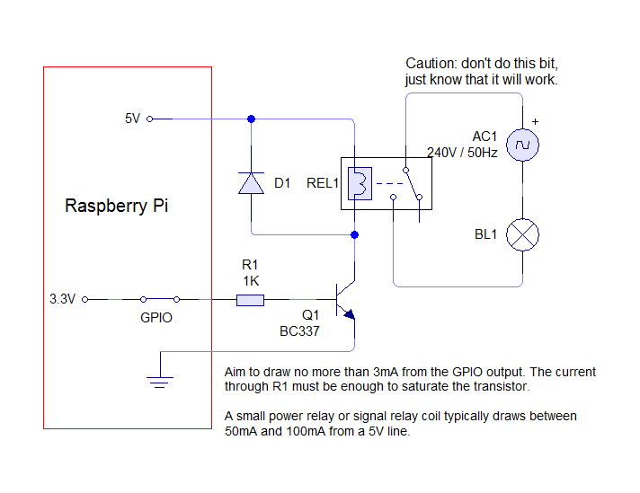
Couple of items on your schematic:
- The "Element Power On" light (BL1 in your schematic) needs to be in parallel with the element, not in series.
- I wouldn't recommend driving a high current relay/contactor from a PID. Mechanical contacts have a much lower cycle life than SSR's. I have included a schematic below that buffers the GPIO output to drive an SSR. The 180 ohm resistor should give something on the order of 20 mA to drive the SSR.
View attachment 284374
Brew on
thats my only option at this point. ive gotten the ssr to fire off somehow. but when i set it to off, the ssr starts blinking on and off
I got it working in mock up. I'm using a crydom ssr hooked up to some reptile tape for duty cycle testing. So far it's working right. My only concern is with the way the gpio handles it's state when not called upon. I also have a 2channel relay board hooked up for switches and when Elsinore isn't running it's like the pins are producing a small amount of current, almost like it's between inverted and not inverted. The ssr board dimly lights up on both channels until the jar file fires up, then it behaves appropriately. Also I have a major concern with using the pi to drive SSRs directly. I don't know if it's a usual occurrence but I advise not hooking up the mains power to the ssr until you setup the pid in the software then REBOOT before trying to use the ssr. Every time I tried to setup the pid I'd get pulsing on the ssr pin until I totally shut down the system and then restarted. And that is a big no no in my book. I thought it was because I was using a known bad ssr because it had an activity led built in. But it was, in fact, the gpio pulsating for no ****ing reason, even if I turned it off and shutdown Elsinore. I am going to drive the ssr with a fet or tranny like is recommended but even so I think I'll have to write up a small script that waits until Elsinore is loaded to trip a main relay so I don't have as much worry of dry firing or something worse.
a small amount of current, almost like it's between inverted and not inverted. The ssr board dimly lights up on both channels until the jar file fires up, then it behaves appropriately.
Also I have a major concern with using the pi to drive SSRs directly. I don't know if it's a usual occurrence but I advise not hooking up the mains power to the ssr until you setup the pid in the software
then REBOOT before trying to use the ssr.
Every time I tried to setup the pid I'd get pulsing on the ssr pin until I totally shut down the system and then restarted.
And that is a big no no in my book. I thought it was because I was using a known bad ssr because it had an activity led built in. But it was, in fact, the gpio pulsating for no ****ing reason, even if I turned it off and shutdown Elsinore. I am going to drive the ssr with a fet or tranny like is recommended but even so I think I'll have to write up a small script that waits until Elsinore is loaded to trip a main relay so I don't have as much worry of dry firing or something worse.
Also I have a major concern with using the pi to drive SSRs directly. I don't know if it's a usual occurrence but I advise not hooking up the mains power to the ssr until you setup the pid in the software then REBOOT before trying to use the ssr.
This is standard on almost all boards, pins are not initialized by default and they are floating.
This is electrical safety 101... Never make a system live until you are going to use it.
Unless you have Elsinore (or another script) setup to run at boot, the GPIOs will go back to floating.
Which mode of Pi are you using? I wonder if there's hardware changes.
Again, this is what happens with all GPIO pins in my experience, they aren't designed to be initialized on startup (you can initialize to IN, OUT, various PWM/I2C modes, etc...)
Never ever plug the mains in, or use a kill switch when the system is not in use. Electrical safety 101.
I didn't see anywhere in the ui where I could use a digital io for this.
I fully intend to use fet's and proper resistors and such once I start the build out. But this pulsing io is a bit puzzling to me. Since I started from scratch and wiped everything out figuring it was some kind of bug. But it carried over to the new setup. As far as using the sonic range sensor. I was intending to put it facing down a sightglass. I already know it's not necessarily gonna work. Just an idea. And I never intended to use it in the boil just in my hlt. And maybe down the road something similar in the mlt so I could eventually use it to control the pumps for precision fly sparging.


