• Please visit and share your knowledge at our sister communities:
  • If you have not, please join our official Homebrewing Facebook Group!

    Homebrewing Facebook Group

Nessie's Dope Ass Brew-Haus V2.0

Homebrew Talk

Help Support Homebrew Talk:

This site may earn a commission from merchant affiliate links, including eBay, Amazon, and others.
If the house is designed to have 3 wire 220v, is it likely that a neutral even exists?

The ground doesn't come into your house from the pole, the neutral does. The ground is from, well, the ground. Typically from two places at least 6' apart. One is normally a grounding rod, the other (at least my circa 1930s home) is a #6 bare copper wire clamped to the metal water line coming into the house. Go out and look at your weatherhead. The neutral is the bare wire, the other two are the hot legs. You'll have 120 v across the neutral and either hot leg and 240 across the two hot legs. Please be careful.
 
I dont think three-wire 220 outlets are even code any more.

I'm looking in Art 406 of the NFPA 70 and Art. 260 of the Virginia Construction Code and I can't find anything that says it's contrary to. Would be great if I could, because then I could wave that in the electricians face and probably get rework done for free ninety nine!
 
I think Art. 404.2(c) of NFPA 70 is the best bet, though in my situation I think there could be an argument for being able to install the neutral line without affecting the finish. I don't own the code yet, so I can't quote it (website doesn't allow copy-pasting), but here is an article concerning the matter: http://ecmweb.com/code-basics/switches-receptacles-and-panelboards
 
Last edited:
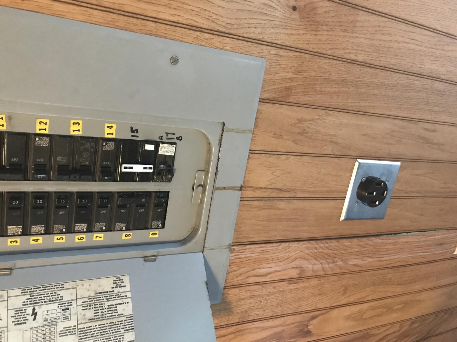
50 Amp GFCI breaker and a new 4 wire outlet installed, seems to work alright and I only got shocked a few times ;)

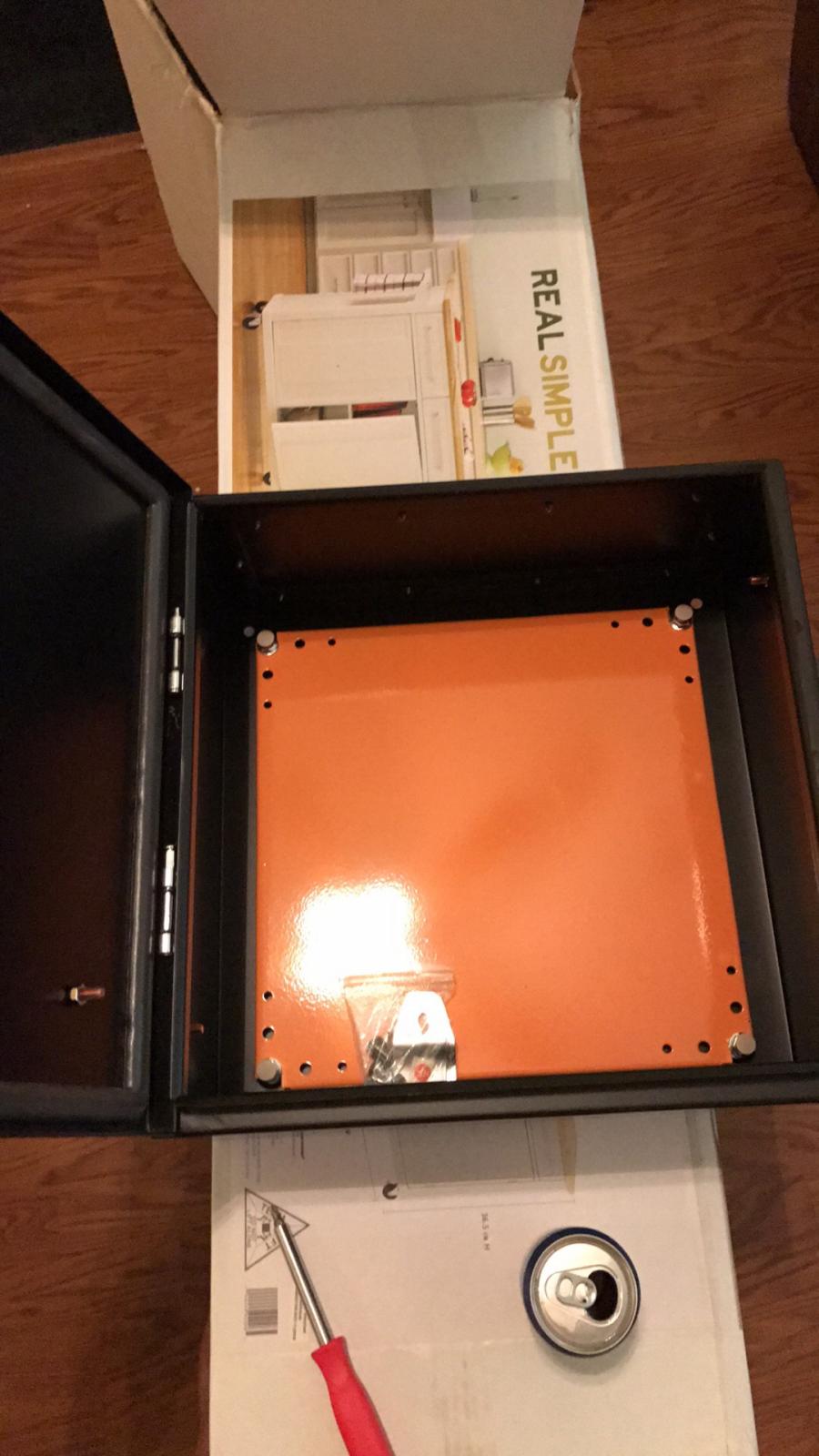
Anyone have recommendations for hole sizes for L5-15 and L6-30 NEMA flanged outlets? I'm also on the lookout for some clean minimilistic Cat 5e ports to install on the bottom of the control panel.

IMG_0038.jpg


IMG_0037.jpg


1BB7ECD5-8F90-4596-A7DB-901EC2A636FE.jpg
 
And if your plans were to use just the CAT5 plugs and connectors with external devices like temperature probes, you may find there is no good way to terminate the stranded wire to the connector.
Many of those connectors are designed to connect only to solid conductor CAT5 cable. As BrunDog said, you need the right connectors and wire for the intended purpose.
 
I personally don't think Ethernet wire should be used for control systems. Too rigid and single conductor not ideal for application.

It's much less rigid than any of the other wires that will be plugging into the panel. How do you mean
 
And if your plans were to use just the CAT5 plugs and connectors with external devices like temperature probes, you may find there is no good way to terminate the stranded wire to the connector.
Many of those connectors are designed to connect only to solid conductor CAT5 cable. As BrunDog said, you need the right connectors and wire for the intended purpose.

There will only be one lan connection. That's from the BCS to the bottom of the panel and then out to a router. I'm not sure what you mean here. Maybe you could be more clear. I think there are some assumptions you are making about my build that I'm not aware of. I will not be connecting lan cables to my temperature probes. :confused:
 
The conductors I'll be using to connect the power supplies to the components will be a mixture of 16 AWG primary wire and 10 AWG THHN, both are stranded wires.

I ordered one of these bad boys to resolve my CAT 5e port question:

https://www.dalco.com/p-10525-dalco...anelmount-bulkhead-coupler-with-dust-cap.aspx

Gotta dig the dust cap.

As far as the hole sizes for the different flanged outlets, the specifications for them don't seem to match a specific hole size so I just picked up the closest hole saw in millimeters (50 mm and 40? maybe.. /shrug)
 
There will only be one lan connection. That's from the BCS to the bottom of the panel and then out to a router. I'm not sure what you mean here. Maybe you could be more clear. I think there are some assumptions you are making about my build that I'm not aware of. I will not be connecting lan cables to my temperature probes. :confused:

You should be fine then.
Sorry if I wasn't being sufficiently clear. Sometimes you see folks using material for applications for which they were never designed, and I mistakenly made that assumption.
 
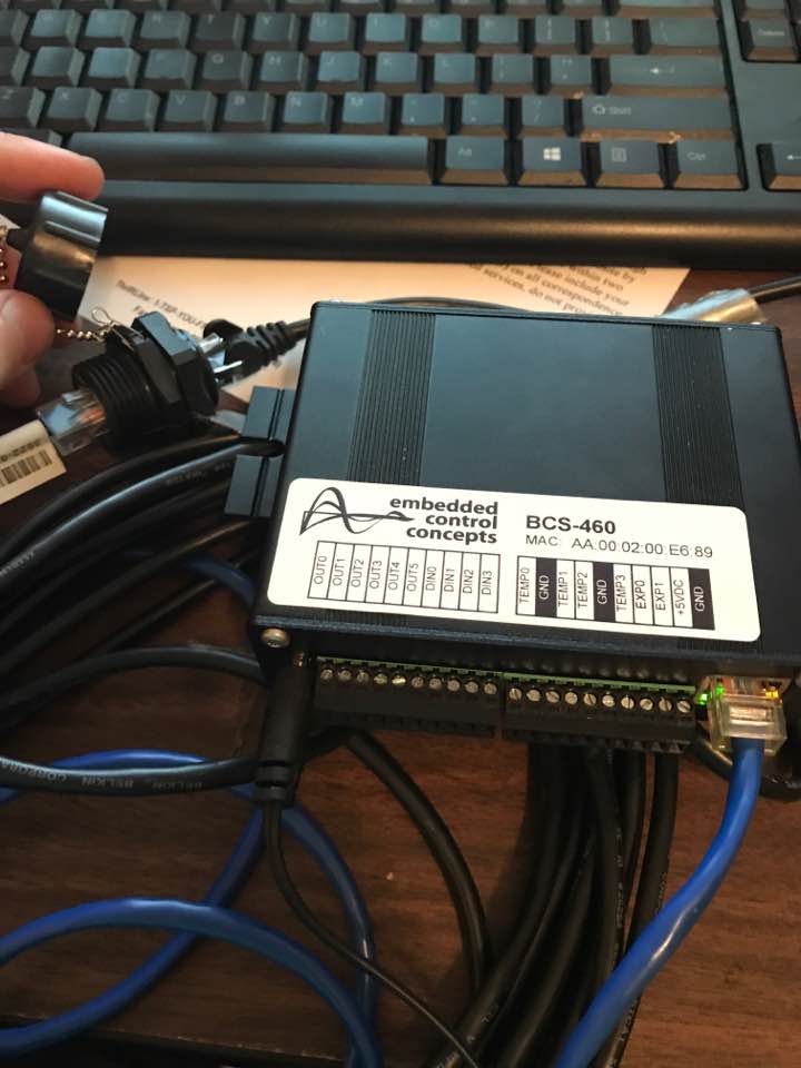
Testing out the connector I was talking about earlier. It's real simple, perfect. And I love the dust cap ;)

cat6 panel connector.jpg
 
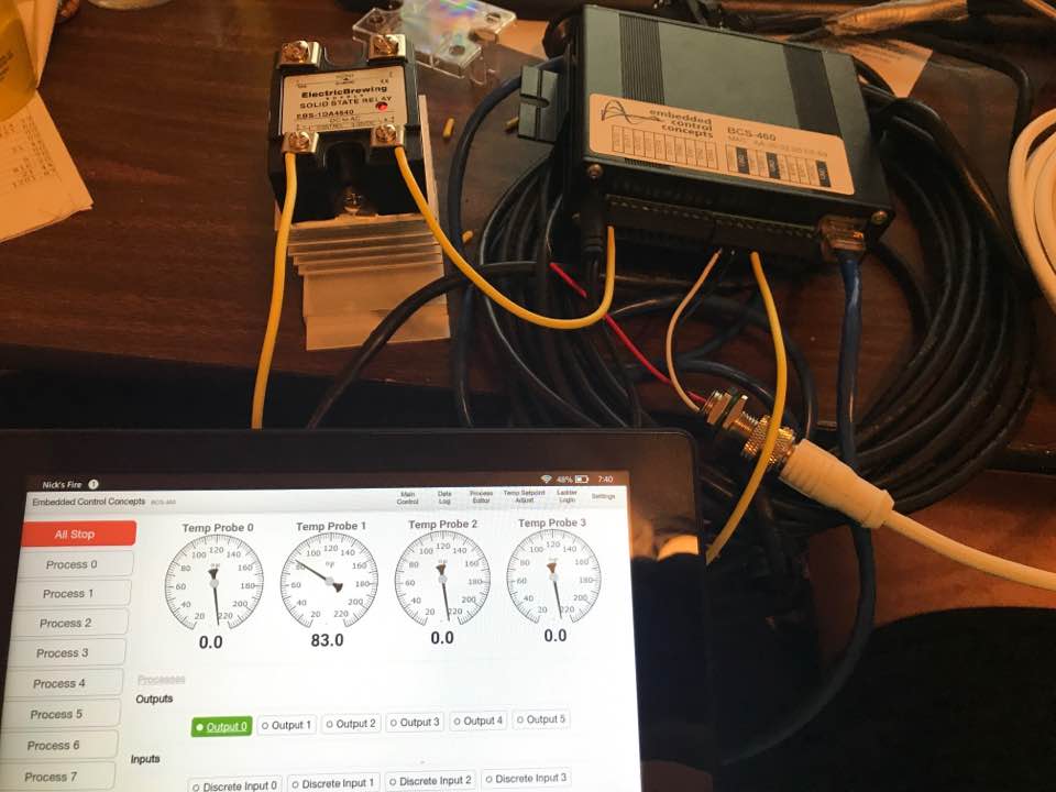
Bought a 7" amazon fire tablet for 30 bucks that will mount onto the front of the panel. Testing the SSRs and temperature probes, everything looks satisfactory so far.

Relay and Temp Probe testing.jpg
 
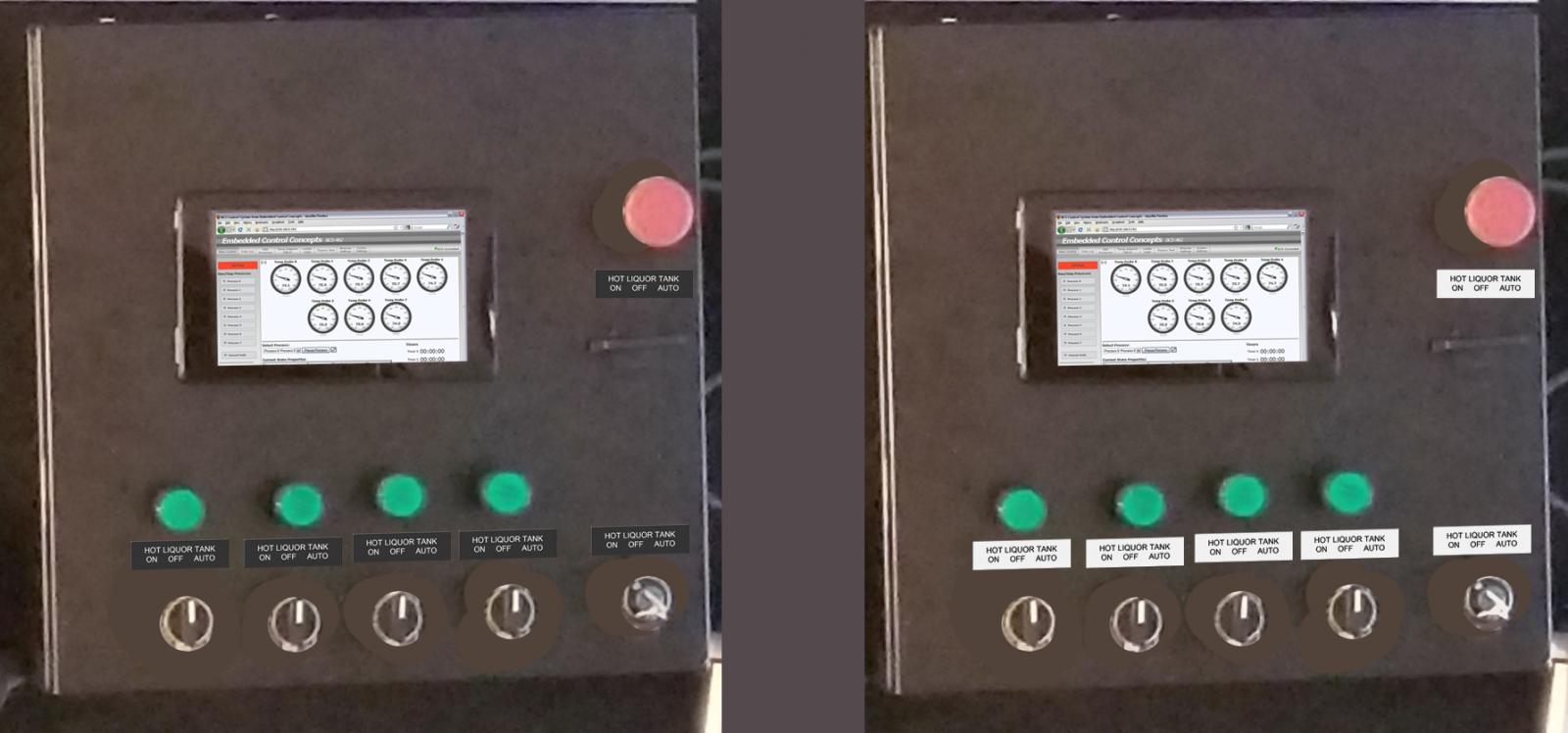
This is a preview of what I think will be the layout for the control panel. I am pretty set on the placement of the components.

The question here is black labels with white lettering or white labels with black lettering!

I am leaning towards black labels with white lettering. Shout out to the GF for the sooper quick shoop.

P.S.

A glow in the dark option is available for +$1... might need that.

previews.jpg
 
Maybe we could help with your Neutral conundrum if you would pop the cover off of your panel and take a nice detailed pic of the inside.
 
Maybe we could help with your Neutral conundrum if you would pop the cover off of your panel and take a nice detailed pic of the inside.


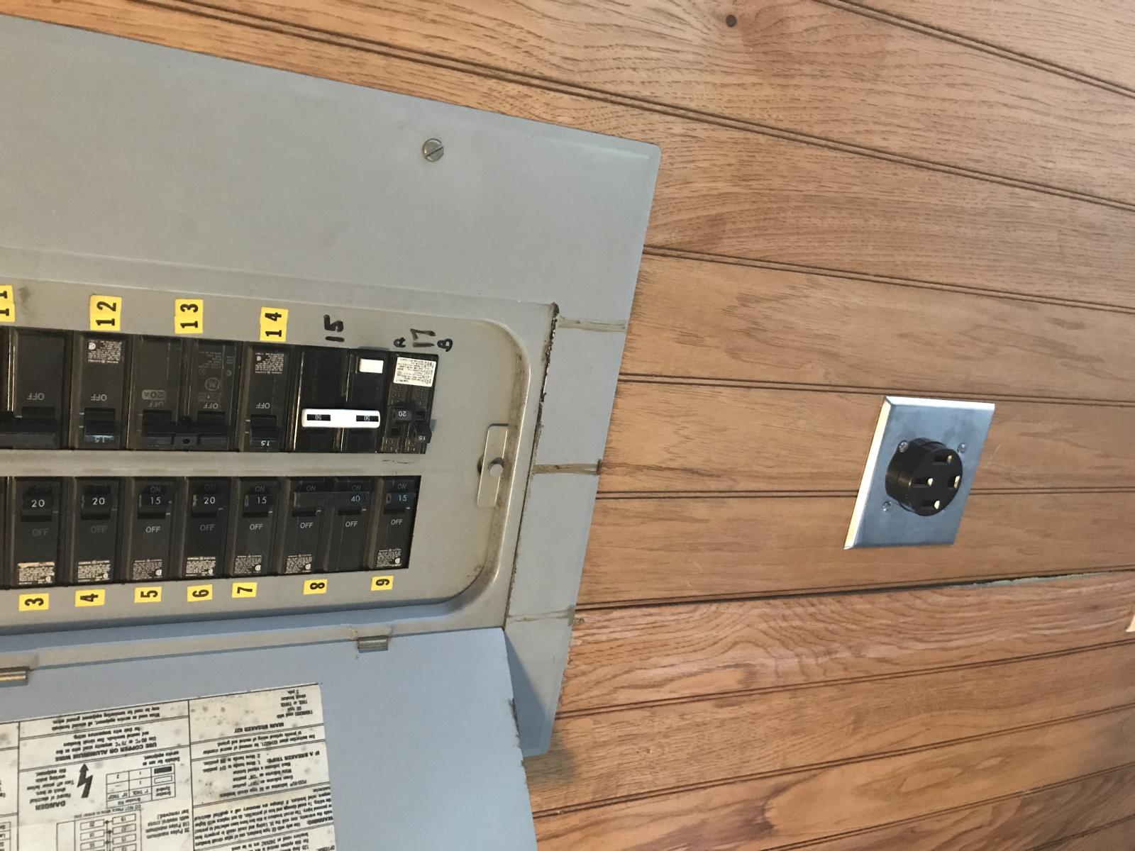
I fixed that issue a while ago, but we covered the solution in previous posts in this thread. Here's the new plug, the CB is #15. Only had to chop my pinky off for it.

This way I wont have to worry about any funky transformers or buying new pumps, will just have 4 busses inside the panel for HHNG. I'm all set up to start drilling holes in the control panel and wiring in components, just gotta make time to do it! :D

IMG_0038.jpg
 
Last edited:
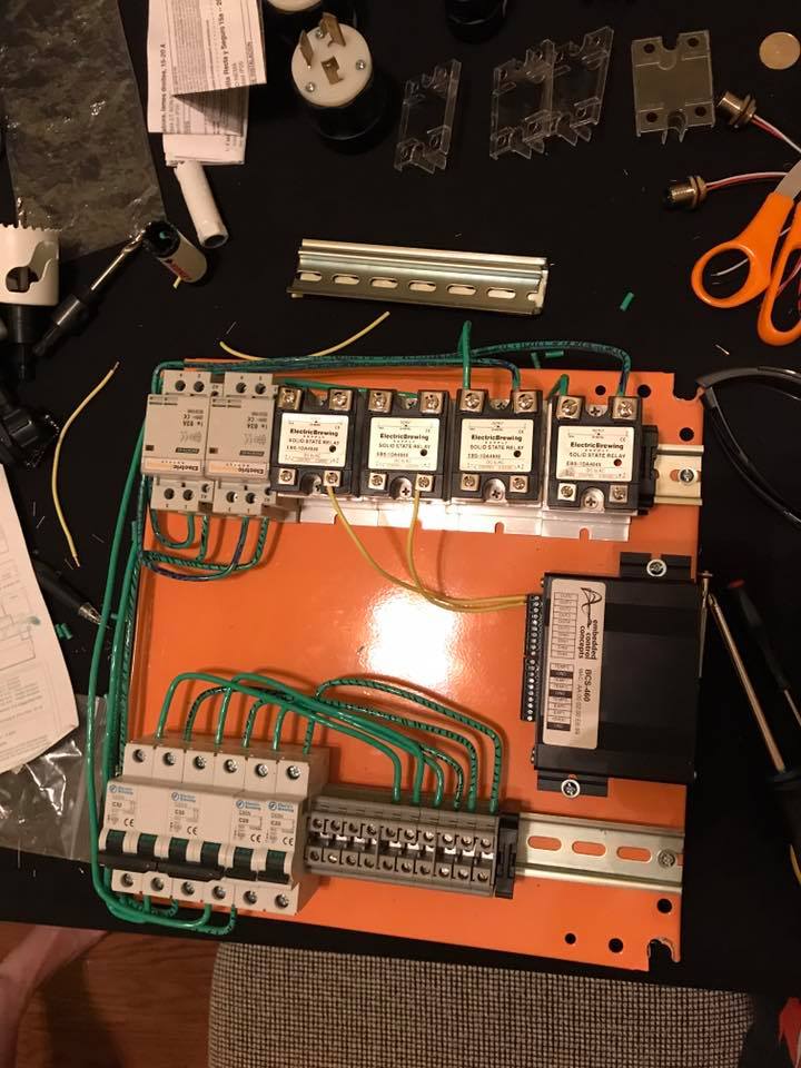
Some wiring progress! Realized I only bought one color wire for the AC stuff, so i put some tiger stripes on em. There's black and purple tiger stripes, but it's hard to tell in the picture.

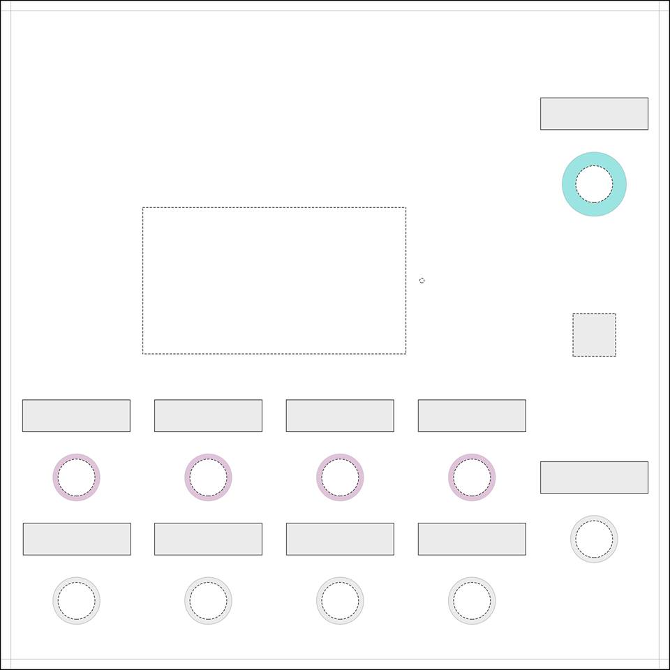
Heading to the print shop right now to get my template printed out in some large B&W formats! Then I'm ready to drill some holes, mount some components and do some more wiring! Another shout out to my wonderful S.O. for making these in PS :D Girls are cool.

wiring progress.jpg


control panel template.jpg


template mockup.jpg
 
View attachment IMG_0089.jpgView attachment IMG_0090.jpgView attachment 52980772825__F0CFD944-5C4E-4E33-871D-EF41F4A520BB.jpgView attachment 52980778089__07CC6C9F-8FC4-41E4-AA3F-AF7CC4B77180.jpgView attachment 52980791624__E2D343D4-1FA6-46B6-9861-EE4518397050.jpgView attachment 52980803300__F7B91387-CC3E-4B91-B7AE-7D356A822765.jpg

Finally got around to making some more progress. Mapped out the holes for the pump/heater receptacles, main power and ethernet connection. Center punched locations, pilot holed and then hole sawed with lubricant. Went pretty smooth, little better than the front though i still had to file down a couple of the bigger holes for the heating elements. At the end of the day everything fits like a glove and i should have enough room to manipulate wires on the inside.

Not pictured is the main power cord, about 8 feet of 6/4 (or "6/3 with ground" i dont get why the big box stores label it like that..) with the plug installed. That was a b!$ch!

More to follow! Soon! Maybe!
 
Hey guys! Still not dead, woohoo!

I just about finished wiring everything up, but i'm having two issues when I plug in the panel.

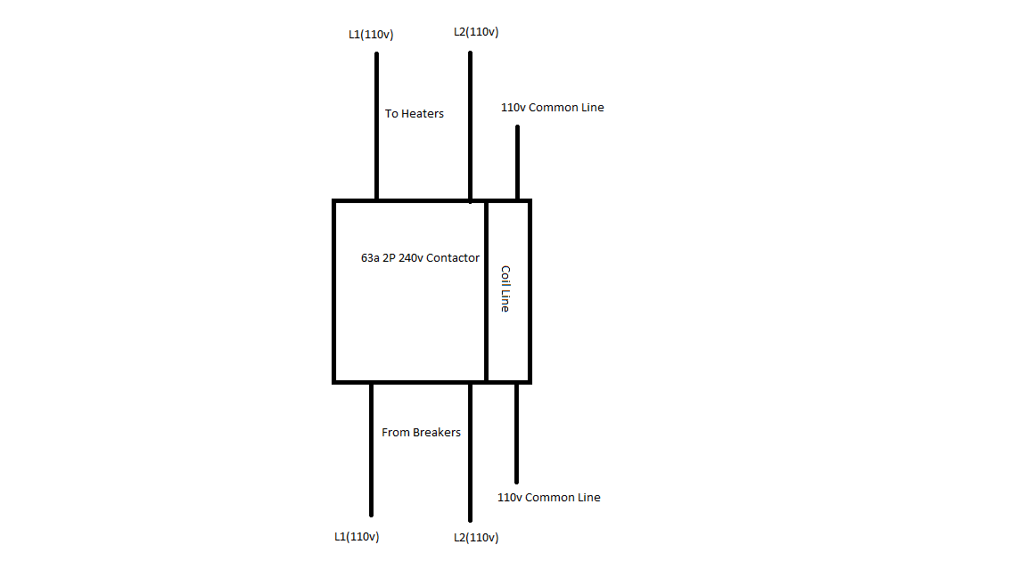
1) I have a 220v contactor that has a 220v coil. Does anyone have a good wiring diagram for this? I currently have 110 going into the coil, then realized it was rated for 220v when it wasn't opening as expected. This is the contactor: https://ebrewsupply.com/collections...ducts/2-pole-63a-220v-coil-din-rail-contactor. Ebrewsupply's learning site says "For 220v coil we would typically tie the common wire to the second leg of the contactor.", but I'm having a bit of trouble understanding how this is implemented. Currently I'm thinking that I need to splice the second leg to the common leg, but then wouldn't I have 220v on one side of the coil voltage and 110 on the other side? What happens when you supply 220 to a 110 leg? Just having trouble wrapping my head around this.

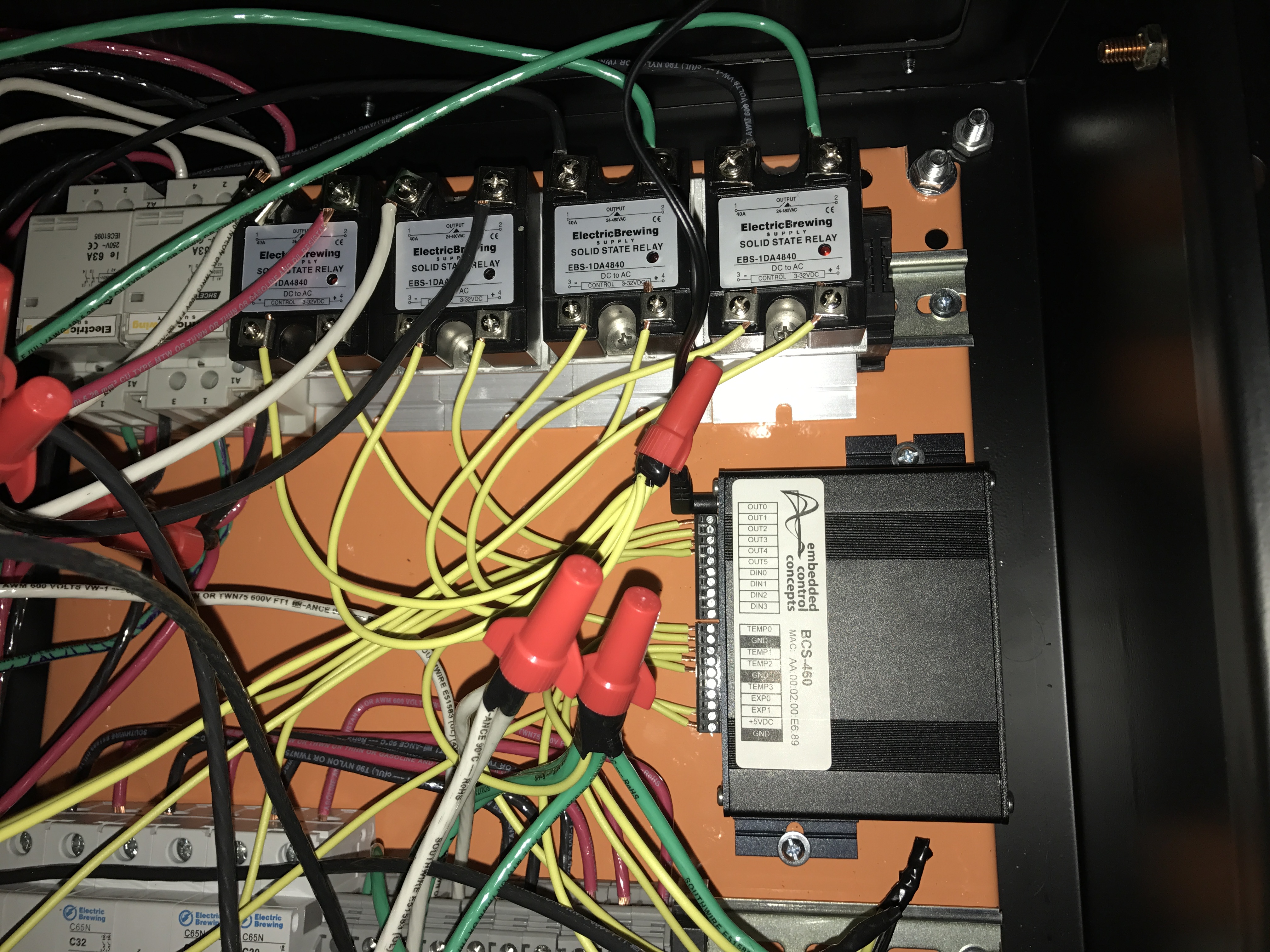
2) This one is more confusing to me: When I take a three position, ON-OFF-AUTO switch to ON or AUTO and back to OFF the relays that receive an output signal from the BCS continue to send an output signal. So the switch will be in OFF, though the relays remain energized. I'm inclined to think it's a BCS software configuration issue, but I'm just not sure.

Other than that, the GFCI breaker remained shut and the panel itself wasn't energized! Lots of success in the initial powering of the control panel, so I'm pretty happy all around. Needs a little bit of wire housekeeping, some of the connections are more exposed than they should be, but overall a good build.

I've attached a couple images to help with the troubleshooting. Thanks for any input!!
Contactor.png
IMG_0171.JPG
 
I think I figured out how to fix the first issue. Assuming L1 is running to the input of the contactor coil, I just splice into L2 and route that to the "output" of the contactor coil providing 220v to the coil to shut it.
 
I think I figured out how to fix the first issue. Assuming L1 is running to the input of the contactor coil, I just splice into L2 and route that to the "output" of the contactor coil providing 220v to the coil to shut it.
No, no, no. Never, ever, connect L1 to L2. That's a short across your 240V power, and will trip your breaker (unless the shorted wires burn out first.)

For a 240V coil, you need to connect L1 to one side of the coil and L2 to the other side. You then control the contactor by switching the L1 coil wire, the L2 coil wire, or both (best if this is the main power contactor.)

Some general comments:
  1. You shouldn't have green wires connected on the power side of two of your SSR's. Green wire should only be used for ground wires. Power SSR connections should only be L1 or L2, which should be red or black wire.
  2. You shouldn't have white wires connected to the power input/output of an SSR. You should be switching L1 or L2 with the SSR, not neutral. L1 and L2 should be black or red. White is for neutral only, not voltage carrying wires.
  3. Your heatsinking of the SSR's may be inadequate, which could cause your SSR's to overheat and fail. The way you have them arranged, they will get very little airflow across/thru them. You might get enough cooling if the DIN rail, on which the HS's are mounted, has good thermal contact with the backpanel in the enclosure. I would never mount SSR's/heatsinks the way you have.
Brew on :mug:
 
Thanks for the reply. What you suggested for the 220v coil is what i was trying to convey. When you connect L1 and L2 through the coil you're still connecting them or shorting them like you say. Whats the difference between that and say completing a circuit in any other load? What did you think i was going to do? This is for the heating element btw.

No, no, no. Never, ever, connect L1 to L2. That's a short across your 240V power, and will trip your breaker (unless the shorted wires burn out first.)

For a 240V coil, you need to connect L1 to one side of the coil and L2 to the other side. You then control the contactor by switching the L1 coil wire, the L2 coil wire, or both (best if this is the main power contactor.)

Some general comments:
  1. You shouldn't have green wires connected on the power side of two of your SSR's. Green wire should only be used for ground wires. Power SSR connections should only be L1 or L2, which should be red or black wire.
  2. You shouldn't have white wires connected to the power input/output of an SSR. You should be switching L1 or L2 with the SSR, not neutral. L1 and L2 should be black or red. White is for neutral only, not voltage carrying wires.
  3. Your heatsinking of the SSR's may be inadequate, which could cause your SSR's to overheat and fail. The way you have them arranged, they will get very little airflow across/thru them. You might get enough cooling if the DIN rail, on which the HS's are mounted, has good thermal contact with the backpanel in the enclosure. I would never mount SSR's/heatsinks the way you have.
Brew on :mug:
 
Back
Top