You are using an out of date browser. It may not display this or other websites correctly.
You should upgrade or use an alternative browser.
You should upgrade or use an alternative browser.
Native ESP8266 BrewPi Firmware - WiFi BrewPi, no Arduino needed!
- Thread starter Thorrak
- Start date

Help Support Homebrew Talk:
This site may earn a commission from merchant affiliate
links, including eBay, Amazon, and others.
Yes, but I’m not at home to ship them out at the moment, unfortunately.Hi gents, Im looking at making a few more of these controllers and was wondering if anyone has a link to some decent PCBs. I brought a few a few years back but they had the space for the IC convertors which arent needed. @Thorrak Do you sell your PCbs?
I have all of my PCB designs (with links to fabricators) on GitHub here: thorrak/thorrak_hardware
If there is anything missing that you’re looking for, let me know and I’ll see if I can upload it.
Cheers for that. I was looking at this board here as I dont need the level shifter.Yes, but I’m not at home to ship them out at the moment, unfortunately.
I have all of my PCB designs (with links to fabricators) on GitHub here: thorrak/thorrak_hardware
If there is anything missing that you’re looking for, let me know and I’ll see if I can upload it.
https://github.com/brewpi-remix/brewpi-pcb-rmx/tree/master/ESP8266 Boards/WeMos D1 Mini Breakout
But what is all of this for as I never used any of those components on my last build?
- 2 x 1.0uF Capacitor (C1, C3)
- 2 x 0.1uF Capacitor (C2, C4)
- 2 x 2N7000 N-Channel MOSFET (Q1, Q2)
- 5 x 10kΩ 1/4-Watt Resistor (R1-R4)
- 1 x 2.2kΩ 1/4-Watt Resistor (R5)
The mosfet and 10ks are the level shifter.Cheers for that. I was looking at this board here as I dont need the level shifter.
https://github.com/brewpi-remix/brewpi-pcb-rmx/tree/master/ESP8266 Boards/WeMos D1 Mini Breakout
But what is all of this for as I never used any of those components on my last build?
- 2 x 1.0uF Capacitor (C1, C3)
- 2 x 0.1uF Capacitor (C2, C4)
- 2 x 2N7000 N-Channel MOSFET (Q1, Q2)
- 5 x 10kΩ 1/4-Watt Resistor (R1-R4)
- 1 x 2.2kΩ 1/4-Watt Resistor (R5)
The capacitors are decoupling caps - they’re optional, but highly recommended.
The 2.2k resistor is the pull-up for the temp sensor - I guarantee you had one of these (or a 4.7k) as they’re required for the temp sensors to work.
Ahh ok so dont need the mosfet and 10ks then as I dont use the level shifter.The mosfet and 10ks are the level shifter.
The capacitors are decoupling caps - they’re optional, but highly recommended.
The 2.2k resistor is the pull-up for the temp sensor - I guarantee you had one of these (or a 4.7k) as they’re required for the temp sensors to work.
Ill use the caps...
And yes I did use the pull up resistor on my other builds.
Thanks for that..
So is that price $15 for 1 board through Oshpark?
I think it's for 3. Oshpark is more expensive but by far the best and most consistent service. You can use just about any other service you like, but I find I get less hate mail with links to Oshpark. 

$479.00
$559.00
EdgeStar KC1000SS Craft Brew Kegerator for 1/6 Barrel and Cornelius Kegs
Amazon.com

$33.99 ($17.00 / Count)
$41.99 ($21.00 / Count)
2 Pack 1 Gallon Large Fermentation Jars with 3 Airlocks and 2 SCREW Lids(100% Airtight Heavy Duty Lid w Silicone) - Wide Mouth Glass Jars w Scale Mark - Pickle Jars for Sauerkraut, Sourdough Starter
Qianfenie Direct

$58.16
HUIZHUGS Brewing Equipment Keg Ball Lock Faucet 30cm Reinforced Silicone Hose Secondary Fermentation Homebrew Kegging Brewing Equipment
xiangshuizhenzhanglingfengshop

$20.94
$29.99
The Brew Your Own Big Book of Clone Recipes: Featuring 300 Homebrew Recipes from Your Favorite Breweries
Amazon.com

$22.00 ($623.23 / Ounce)
AMZLMPKNTW Ball Lock Sample Faucet 30cm Reinforced Silicone Hose Secondary Fermentation Homebrew Kegging joyful
无为中南商贸有限公司

$53.24
1pc Hose Barb/MFL 1.5" Tri Clamp to Ball Lock Post Liquid Gas Homebrew Kegging Fermentation Parts Brewer Hardware SUS304(Liquid Hose Barb)
yunchengshiyanhuqucuichendianzishangwuyouxiangongsi

$176.97
1pc Commercial Keg Manifold 2" Tri Clamp,Ball Lock Tapping Head,Pressure Gauge/Adjustable PRV for Kegging,Fermentation Control
hanhanbaihuoxiaoshoudian

$53.24
1pc Hose Barb/MFL 1.5" Tri Clamp to Ball Lock Post Liquid Gas Homebrew Kegging Fermentation Parts Brewer Hardware SUS304(Liquid Hose Barb)
Guangshui Weilu You Trading Co., Ltd

$7.79 ($7.79 / Count)
Craft A Brew - LalBrew Voss™ - Kveik Ale Yeast - For Craft Lagers - Ingredients for Home Brewing - Beer Making Supplies - (1 Pack)
Craft a Brew

$10.99 ($31.16 / Ounce)
Hornindal Kveik Yeast for Homebrewing - Mead, Cider, Wine, Beer - 10g Packet - Saccharomyces Cerevisiae - Sold by Shadowhive.com
Shadowhive
Hi Brewers, In using this relay in a build and having problems with it (Similar to last time way back in post 2640 which Ive re read but still not sure) Ive got them set to Inverted in the software,
Ive got the jumpers both on Low-Com (Although not shown in this photo) But every time I turn the power on I get one of the relays on or both on even though it says waiting to heat or waiting to cool.
From memory (As Im now at work) with both jumpers set to high-com both relays come on. With both jumpers off no relays are on and with both jumpers set low-com one relay comes on (Even though its Waiting to heat or waiting to cool). Im already confused... Any suggestions???
EDIT:- So after reading what I can about these relays am I right in saying that if I switch the jumpers to high-com it means a voltage activates the relay. And if I switch the jumpers to low-com it means no voltage activates the relays?? If so then wouldnt changing the settings in the software to inverted then do the opposite again??? So high-com switches on high voltage but set to inverted will switch it on low even though the jumpers are set to high??
If thats correct whats the point of the inverted or non inverted setting?

Last edited:
Set the relays for Low Active.
Then configure the GPIO pins that drive the relays for "inverted".
LEDs D3 and D4 will light when their respective relays are activated when the end to end setup is properly configured.
Most relay modules are Low Active, period, which is why the gui offers the option of inverting the relay controls...
Cheers!
Ok thanks for that. I will give it a shot.Set the relays for Low Active.
Then configure the GPIO pins that drive the relays for "inverted".
LEDs D3 and D4 will light when their respective relays are activated when the end to end setup is properly configured.
Most relay modules are Low Active, period, which is why the gui offers the option of inverting the relay controls...
Cheers!
So nothing would work other than setting the pins to com-high but in the software setting them both to non-inverted. If I set the pins to com-low and used "inverted" both relays switched on straight away. Strange indeed


DuncB
Well-Known Member
Should both of those jumpers be in?
Yes, 1 for each relay.Should both of those jumpers be in?
DuncB
Well-Known Member
I’ve made 2 temp controllers before with fermentrack installed in a ras-berry Pi so I’m basically just building this one the same. I got all my info for it from this thread . Other than that I’ve never really seen a build guide.@troyp42
Thanks I'm waiting for the parts for my build. Good to know.
Which build guide are you following?
adrianoftyriel
Active Member
- Joined
- Jan 23, 2016
- Messages
- 34
- Reaction score
- 6
@LBussy @Thorrak
I'm not sure if you remember or not, but a while back I was having trouble with intermittent sensors.
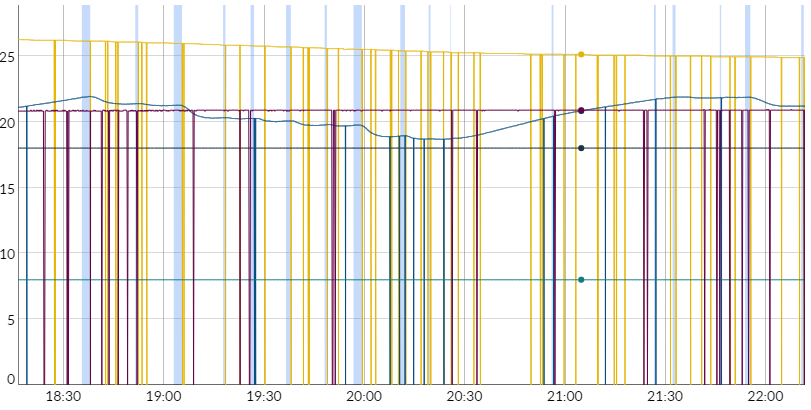
Well, today I finally had some more time to look at it and I cracked the issue: a faulty power supply for my D1 Mini!
Before changing the power supply:

And after (you can see when I changed the power supply and plugged the room sensor back in at 07:50):

So, there you have it: check your power supply!
I'm not sure if you remember or not, but a while back I was having trouble with intermittent sensors.
Well, today I finally had some more time to look at it and I cracked the issue: a faulty power supply for my D1 Mini!
Before changing the power supply:

And after (you can see when I changed the power supply and plugged the room sensor back in at 07:50):

So, there you have it: check your power supply!
@day_trippr would have recommended that first. 
I was just about to state that 
purpleogre
Member
Hi folks, I've just started to re-look at my esp8266 brewpi project that I built back in 2017/18

I added the buzzer function back using an arduino active buzzer module and successfully built the master branch 0.08 and 0.09 versions, this was on another machine using platformio. I have moved over to another pc running ubuntu and so have done a fresh install of platformio and downloaded a fresh copy the master branch before I started to implement the buzzer again.
Trying to compile gave lots of warnings about SPIFFS depreciating and several errors, one error was solved by making the WiFiManager as a local library and changing platformio.ini to reflect the change the other error was 'i' was not declared in this scope in the function 'bool isValidmDNSName(String)' in brewpi-esp8266.cpp I'm not a good coder so after googling a bit I ended up rewriting to be
this has allowed it to successfully compile but i'm getting corruption on the LCD screen, the last update in the master branch says was to fix lcd corrution

Should I be using one of the other Dev branches instead ?

I added the buzzer function back using an arduino active buzzer module and successfully built the master branch 0.08 and 0.09 versions, this was on another machine using platformio. I have moved over to another pc running ubuntu and so have done a fresh install of platformio and downloaded a fresh copy the master branch before I started to implement the buzzer again.
Trying to compile gave lots of warnings about SPIFFS depreciating and several errors, one error was solved by making the WiFiManager as a local library and changing platformio.ini to reflect the change the other error was 'i' was not declared in this scope in the function 'bool isValidmDNSName(String)' in brewpi-esp8266.cpp I'm not a good coder so after googling a bit I ended up rewriting to be
Code:
bool isValidmDNSName( const char * mdns_name )
 {
        char c;
        while ( (c = *mdns_name++) )
          if ( c != '.' && !isalnum(c) )
            return false;
         return true;
}
Should I be using one of the other Dev branches instead ?
Assuming you are using the master branch:
What you've done there is not exactly correct, but I don't believe it's causing your issue. A better change would be:
You can safely (for now) ignore all the SPIFFS warnings. There are a couple of other character conversion warnings that can be ignored for now as well.
In the platformio.ini file, change:
to:
That's all you should need - I just compiled and tested here.
What you've done there is not exactly correct, but I don't believe it's causing your issue. A better change would be:
C++:
bool isValidmDNSName(String mdns_name) {
    for (int i = 0; i < mdns_name.length(); ++i) {
        if (!isalnum(mdns_name[i]))
            return false;
    }
    return true;
}
You can safely (for now) ignore all the SPIFFS warnings. There are a couple of other character conversion warnings that can be ignored for now as well.
In the platformio.ini file, change:
INI:
lib_deps =
  https://github.com/tzapu/WiFiManager.git#development
INI:
lib_deps =
  https://github.com/tzapu/WiFiManager.git
That's all you should need - I just compiled and tested here.
purpleogre
Member
thanks @LBussy , I changed the brewpi-esp8266.cpp isValidmDNSName to your Code which works  but changing platformio.ini to your suggestion I get an error FileNotFoundError: [Errno 2] No such file or directory: 'git':
so for the time being I've set the common section of platformio.ini to
which lets me compile and upload ok , unfortunately the screen is still corrupt :-(
If I use Fermentrack to grab the latest and flash it works fine !
for completeness here's my change to Buzzer.ccp
and
in config.h I've made the following changes
so for the time being I've set the common section of platformio.ini to
INI:
[common]
platform = espressif8266
board = nodemcuv2
framework = arduino
lib_deps =
    tzapu/WiFiManager@^0.16.0
    ;https://github.com/tzapu/WiFiManager.git
which lets me compile and upload ok , unfortunately the screen is still corrupt :-(
If I use Fermentrack to grab the latest and flash it works fine !
for completeness here's my change to Buzzer.ccp
C++:
/*
 * Buzzer.cpp
 *
 * Copyright 2012-2013 BrewPi.
 *
 * This file is part of BrewPi.
 *
 * BrewPi is free software: you can redistribute it and/or modify
 * it under the terms of the GNU General Public License as published by
 * the Free Software Foundation, either version 3 of the License, or
 * (at your option) any later version.
 *
 * BrewPi is distributed in the hope that it will be useful,
 * but WITHOUT ANY WARRANTY; without even the implied warranty of
 * MERCHANTABILITY or FITNESS FOR A PARTICULAR PURPOSE.  See the
 * GNU General Public License for more details.
 *
 * You should have received a copy of the GNU General Public License
 * along with BrewPi.  If not, see <http://www.gnu.org/licenses/>.
 */


#include "Brewpi.h"
#include "Ticks.h"
#include "Pins.h"
#include "Buzzer.h"

// TODO - Implement

#if BREWPI_BUZZER
#if BREWPI_BOARD == BREWPI_BOARD_ESP8266
#define _delay_ms(ms) delayMicroseconds((ms) * 1000)
#endif
#if BREWPI_BOARD != BREWPI_BOARD_ESP8266
#include <util/delay.h>
#endif

#include "FastDigitalPin.h"

#if (alarmPin != 0)
    #error "Check PWM settings when you want to use a different pin for the alarm"
#endif

#define BEEP_ON() digitalWrite(alarmPin, LOW);
#define BEEP_OFF() digitalWrite(alarmPin, HIGH);

void Buzzer::init(void){
    // set up square wave PWM for buzzer
    fastPinMode(alarmPin,OUTPUT);


}

void Buzzer::setActive(bool active)
{
    if (active!=this->isActive()) {
        ValueActuator::setActive(active);
        if (active) {
            BEEP_ON();
        }
        else {
            BEEP_OFF();
        }
    }
}

void Buzzer::beep(uint8_t numBeeps, uint16_t duration){
    for(uint8_t beepCount = 0; beepCount<numBeeps; beepCount++){
        BEEP_ON();
        wait.millis(duration);
        BEEP_OFF();
        if(beepCount < numBeeps - 1){
            wait.millis(duration); // not the last beep
        }
    }
}

Buzzer buzzer;

#endifin config.h I've made the following changes
C++:
#ifndef BREWPI_BUZZER
#define  BREWPI_BUZZER 1
#endif
//

#define heatingPin NODEMCU_PIN_D0
#define coolingPin NODEMCU_PIN_D5

#define oneWirePin NODEMCU_PIN_D6  // If oneWirePin is specified, beerSensorPin and fridgeSensorPin are ignored
#define doorPin    NODEMCU_PIN_D7
#define alarmPin NODEMCU_PIN_D3Ah ... so the only reason you are going down this road is to add the buzzer back in?
There's probably a conflict between the pins then. You'll probably have to crawl the pin definitions between the two boards and see where the issue may lie (you can hover over the macros to see what the pin number behind it may be.).
There's probably a conflict between the pins then. You'll probably have to crawl the pin definitions between the two boards and see where the issue may lie (you can hover over the macros to see what the pin number behind it may be.).
purpleogre
Member
lol yes, I'll check on all the pin definitions and I'll start with a fresh instance again and see how I get on tomorrow.
I mean, I wasn't trying to make fun of your desire to have the buzzer - just wanted to make sure why you were going to the effort when the pre-compiled binary is there.
Believe me, I've done more for less.
Believe me, I've done more for less.
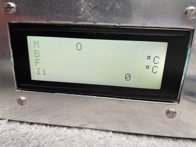
Hi guys. I made 2 of these temp controllers a few years ago and one of them has worked fine...until now. But the other one always had issues where it would lose its temp setting from the probe and just show 2 lines instead. Im currently brewing a lager and it lost its temp reading and climbed from 10C to 13.5C. I would unplug the probes and plug then back in and that would fix the problem but the temp would still have climb up a few degrees.
But tonight my second temp controller did the same thing. I got home from work and there were two lines instead of the temperature display. I had to unplug the probes and plug them back in to get it to start working again.
Anyone know what this issue could be and how to fix it?

But tonight my second temp controller did the same thing. I got home from work and there were two lines instead of the temperature display. I had to unplug the probes and plug them back in to get it to start working again.
Anyone know what this issue could be and how to fix it?

Often this is because of a faulty or deficient power supply. Sometimes it's the pull-up resistor or the probe.
I'd get a good 2.5A or 3A power supply and use that.
I'd get a good 2.5A or 3A power supply and use that.
DuncB
Well-Known Member
Is a pull up resistor one that bridges between two lines on the DSB temp probe ?
Yep. Sometimes a cold solder joint is at fault. Sometimes it needs a more powerful pull-up (you should use a 2K2 for 3V3 for instance.) I will say that most often this is a power supply.
Yep. Sometimes a cold solder joint is at fault. Sometimes it needs a more powerful pull-up (you should use a 2K2 for 3V3 for instance.) I will say that most often this is a power supply.
I've also seen that lack of temperature display on my FermentTrack rig..... may have happened when the data line of the one-wire bundle got disconnected from the board.... perhaps....
Not that I have personal knowledge or experience with that, mind you.
Chris
I brought and used my power supplies from Jaycar as the original power supply I got from chinabay looked cheap and nasty.Yep. Sometimes a cold solder joint is at fault. Sometimes it needs a more powerful pull-up (you should use a 2K2 for 3V3 for instance.) I will say that most often this is a power supply.
This is the one Im using.. Any good? Or if not what do you suggest?
https://www.jaycar.com.au/15w-5v-3a...os=4&queryId=522157e5c9a484d097d3355356591643
The probes were ebay though (Are they something that can fail over time?)
The 1st temp controller I built did this fairly regularly from when I first built it. Say every 2nd fermentation.
The second one has never done it until now. Im using xlr connectors for both controllers so maybe Ill hard wire one direct and see if that stops failing and switch to the pull up resistors you mention.
Also why would it work fine for days/weeks and then all of a sudden stop working?
Thanks for the tips.
Last edited:
DuncB
Well-Known Member
@troyp42
I'm not interpreting the diagram for how to wire the 2 relays from the vito site very well
Any chance of a photo of how you wired your relays in or a different explanation diagram?
I'm pretty sure that it should be basically the same way as for the connections coming out of the STC 1000, ( as it does a similar job ).
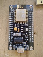
Good news I ordered 3 esp 8266 Lolin boards one of them didn't work from the off not powering up.
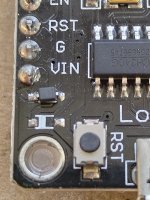
Was reading up about D1 mini as I wanted to repurpose some spare ones as NAT relays but they wouldn't power up because I'd taken off the diode as per ispindel instructions. A reddit post mentioned about non working D1 mini boards and said if missing bridge it.
So I Bridged with a blob of solder on the D1 mini and all good.
Lo and behold looked at the Non functioning ESP 8266 and that diode appeared to be missing. Bridged it and bingo.


Similar threads
- Replies
- 10
- Views
- 2K
- Replies
- 3
- Views
- 2K
- Replies
- 7
- Views
- 2K


![Craft A Brew - Safale BE-256 Yeast - Fermentis - Belgian Ale Dry Yeast - For Belgian & Strong Ales - Ingredients for Home Brewing - Beer Making Supplies - [3 Pack]](https://m.media-amazon.com/images/I/51bcKEwQmWL._SL500_.jpg)


