Native ESP8266 BrewPi Firmware - WiFi BrewPi, no Arduino needed!

Homebrew Talk - Beer, Wine, Mead, & Cider Brewing Discussion Forum

Help Support Homebrew Talk - Beer, Wine, Mead, & Cider Brewing Discussion Forum:

This site may earn a commission from merchant affiliate links, including eBay, Amazon, and others.
Ah ... so the only reason you are going down this road is to add the buzzer back in?

There's probably a conflict between the pins then. You'll probably have to crawl the pin definitions between the two boards and see where the issue may lie (you can hover over the macros to see what the pin number behind it may be.).
 
lol yes, I'll check on all the pin definitions and I'll start with a fresh instance again and see how I get on tomorrow.
 
I mean, I wasn't trying to make fun of your desire to have the buzzer - just wanted to make sure why you were going to the effort when the pre-compiled binary is there.

Believe me, I've done more for less.
 
Hi guys. I made 2 of these temp controllers a few years ago and one of them has worked fine...until now. But the other one always had issues where it would lose its temp setting from the probe and just show 2 lines instead. Im currently brewing a lager and it lost its temp reading and climbed from 10C to 13.5C. I would unplug the probes and plug then back in and that would fix the problem but the temp would still have climb up a few degrees.
But tonight my second temp controller did the same thing. I got home from work and there were two lines instead of the temperature display. I had to unplug the probes and plug them back in to get it to start working again.

Anyone know what this issue could be and how to fix it?

IMG_6648.jpg
 
Often this is because of a faulty or deficient power supply. Sometimes it's the pull-up resistor or the probe.

I'd get a good 2.5A or 3A power supply and use that.
 
Yep. Sometimes a cold solder joint is at fault. Sometimes it needs a more powerful pull-up (you should use a 2K2 for 3V3 for instance.) I will say that most often this is a power supply.
 
Yep. Sometimes a cold solder joint is at fault. Sometimes it needs a more powerful pull-up (you should use a 2K2 for 3V3 for instance.) I will say that most often this is a power supply.

I've also seen that lack of temperature display on my FermentTrack rig..... may have happened when the data line of the one-wire bundle got disconnected from the board.... perhaps.... :rolleyes:

Not that I have personal knowledge or experience with that, mind you.

Chris
 
Yep. Sometimes a cold solder joint is at fault. Sometimes it needs a more powerful pull-up (you should use a 2K2 for 3V3 for instance.) I will say that most often this is a power supply.
I brought and used my power supplies from Jaycar as the original power supply I got from chinabay looked cheap and nasty.
This is the one Im using.. Any good? Or if not what do you suggest?

https://www.jaycar.com.au/15w-5v-3a...os=4&queryId=522157e5c9a484d097d3355356591643

The probes were ebay though (Are they something that can fail over time?)
The 1st temp controller I built did this fairly regularly from when I first built it. Say every 2nd fermentation.
The second one has never done it until now. Im using xlr connectors for both controllers so maybe Ill hard wire one direct and see if that stops failing and switch to the pull up resistors you mention.

Also why would it work fine for days/weeks and then all of a sudden stop working?

Thanks for the tips.
 
Last edited:
@troyp42

I'm not interpreting the diagram for how to wire the 2 relays from the vito site very well

Any chance of a photo of how you wired your relays in or a different explanation diagram?

I'm pretty sure that it should be basically the same way as for the connections coming out of the STC 1000, ( as it does a similar job ).

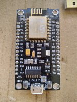
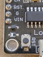
Good news I ordered 3 esp 8266 Lolin boards one of them didn't work from the off not powering up.

Was reading up about D1 mini as I wanted to repurpose some spare ones as NAT relays but they wouldn't power up because I'd taken off the diode as per ispindel instructions. A reddit post mentioned about non working D1 mini boards and said if missing bridge it.
So I Bridged with a blob of solder on the D1 mini and all good.

Lo and behold looked at the Non functioning ESP 8266 and that diode appeared to be missing. Bridged it and bingo.

IMG_20210819_123545.jpgIMG_20210819_123612.jpg
 
@troyp42

I'm not interpreting the diagram for how to wire the 2 relays from the vito site very well

Any chance of a photo of how you wired your relays in or a different explanation diagram?

I'm pretty sure that it should be basically the same way as for the connections coming out of the STC 1000, ( as it does a similar job ).

Good news I ordered 3 esp 8266 Lolin boards one of them didn't work from the off not powering up.

Was reading up about D1 mini as I wanted to repurpose some spare ones as NAT relays but they wouldn't power up because I'd taken off the diode as per ispindel instructions. A reddit post mentioned about non working D1 mini boards and said if missing bridge it.
So I Bridged with a blob of solder on the D1 mini and all good.

Lo and behold looked at the Non functioning ESP 8266 and that diode appeared to be missing. Bridged it and bingo.

View attachment 739589View attachment 739590
ill take a photo tonight when I get home tonight and post it.

Are you talking about this image here? What are you not sure about? the 240v side?

https://github.com/vitotai/BrewPiLess/blob/master/doc/HardwareExample1.md
 
Yep. Sometimes a cold solder joint is at fault. Sometimes it needs a more powerful pull-up (you should use a 2K2 for 3V3 for instance.) I will say that most often this is a power supply.
Hey mate so I replaced the pull up resistor on TC1 the controller that Ive often had issues with and it worked fine for the past 12 days. Then I came home tonight after work and the temp reading was dashed lines again. I unplugged the probes and plugged back in to reset it. TC2 has been working fine the past 12 days but it too failed for the first time back 2 weeks ago. I built these about 3 months apart and the pepper supplies seem to be good quality. They weren't ordered from China via Ebay so what else could be wrong here? A mate of one built one around the same time I did and he has had no issues at all with his.
 
I replaced the pull up resistor on TC1 the controller that Ive often had issues with and it worked fine for the past 12 days. Then I came home tonight after work and the temp reading was dashed lines again. I unplugged the probes and plugged back in to reset it. TC2 has been working fine the past 12 days but it too failed for the first time back 2 weeks ago. I built these about 3 months apart and the pepper supplies seem to be good quality. They weren't ordered from China via Ebay so what else could be wrong here?
Assuming the sensors come back after a reboot, I'd swap them out with a known good (or at least different) 3A or better power supply and see what happens.
 
Assuming the sensors come back after a reboot, I'd swap them out with a known good (or at least different) 3A or better power supply and see what happens.
I dont even have to reboot the TC. I just unplug the sensors and plug them back in again and it works. What power supply do you use?

Should I also consider buying new temp probes or are they not likely to fail? It just seems strange that I have 3 of these. 2 have the same type of power supply but were built about 6 months apart. The 3rd is a brewpiless device with a cheaper 5v power supply I got from Chinabay. They have all failed the same at 1 point with unit 1 failing the most and the unit with the cheap power supply only failing once since I built it 3 months ago.

Ill buy a new power supply and leave it running non stop for a few weeks/months to see what happens. The amte who built his is using the same power supply I am though and hasnt had an issue with his which is really weird.
 
Last edited:
The problem is that the script is no longer detecting the probes. That means either the power is dropping, or you've got bad connections, or bad sensors.

Since there are three sensors, it seems unlikely that all three are having a spurious issue at the same time. It makes more sense to look at the common points: solder junctions, pull-up resistor, power supply.

I assume you are using the correct pull-up (2K2.) If you are using a 4K7 then try a 2K2. If you are using a 2K2, go down to a 1K and see if that helps.

It may also be something to do with your house power (mains you call it I think?) If the compressor kicks on and dims things a bit, it might be causing the issue. That's kinda hard to find without a scope/recording instrument.

Im using only 2 sensors, but yeh I see what you mean. I switched to a 2k2 about 2 weeks ago when you first mentioned it. Ill now try a 1k in one of them and change the power supply out in another but keep the 2k2 and see if either fail.

Mains power issues..hmm. Good point. I have good mains power supply to the house....I have an extension lead plugged into 1 GPO in the garage. From there I have a powerboard plugged in and another powerboard plugged into that. Ive got 2 fermenting fridges (Not always on), a router and ethernet over power device, a fluro light and 1 temp controller all plugged into those 2 powerboards. But.... the 2nd one that also failed is plugged directly into the GPO so that rules out the powerboards being the issue. I doubt if it would be my mains power but if it is what can I do?
 
Run an extension cord (temporarily) to another circuit to power the ESP and see if it's any better.
Would the fridge or heater cutting in and out be the reason for a suspected power drain? If I test them in a different room without anything plugged into the heating or cooling is that defeating the purpose and I should test with a fridge etc connected?
 
Testing without the load/on a different circuit is a good test. Now if that’s what your issue is, you have different choices to make but at least you know what the issue is.
 
Testing without the load/on a different circuit is a good test. Now if that’s what your issue is, you have different choices to make but at least you know what the issue is.
Just thinking about it Ive brewed with both a mash tun and a HLT plugged into the same GPO and the fermenting fridges all at the same time and the units have never dropped out whilst brewing so Im not suspecting the power supply issue from the GPO as that would cause an issue then for sure you would think.
 
You're going to have to methodically isolate the issue - so it doesn't matter what I think. :)

Start by isolating it in large chunks and break it down smaller each time.
 
You're going to have to methodically isolate the issue - so it doesn't matter what I think. :)

Start by isolating it in large chunks and break it down smaller each time.
Ok a question..Should the probes be powered with 3v3 or 5v? Mine are powered with 3v3 from the wemos but Ive seen wiring diagrams that say 5v to the probe. Should I try 5v direct from the power supply?

Ive also noticed that some of the pcbs that Thorrak sells have capacitors on them. Are these smoothing caps?

EDIT- Whilst you sleep..I got home from work, had a beer and thought stuff it, so I desoldered the 3v3 lead from the probe and connected it up to 5v. The data lead still has the 2k2 resistor connected to the 3v3 supply. its working..lets see what happens.
 
Last edited:
The ESP device has plenty of capacity for the load of the probes - and the relays as well. The issue may be the power coming in.

Powering the probes from 5V0 is a good step. Leave the pull-up as 3V3 since the data pins on the ESP are not rated for 5V0.
 
Pullup is a resistor that pulls the voltage in the data line when the probe sets free the line.
the lower the value more current will flow and will pull up faster.
4k7 is traditional for 5v supply. 3k3 with 3,3v but can be as low as 820 ohms.
 
Pull-up power is not as magic as it sounds. Here's a really simplified description:
  • The controller is told to read the digital pin. It will either be "high" (~3v3) or "low" (0V). In reality, the voltages are slightly different but let's use these for the sake of argument
  • The sensor will send its data digitally through a series of 1's (low) or 0's (high)
  • Having said that, the sensor doesn't actually "send" data, it effectively grounds out the data line making the detected value 0V
Q: What's the value of the data pin when the sensor is not "grounding" it?
A: It could be anything. With (almost) no load on that line, the controller can see it high, low, or warbling in between. I've seen 200+ volts "indicated" on a bare wire laying on my desk. Touch it and it will not shock you of course, but referenced to earth, it could be a lot higher than you think.

This is why we need the pull-up; to provide a definite referenceable voltage.
  • A pull-up is like a hose, filling a bucket of water. It "pulls up" the line, imagine that as filling a bucket
  • The sensor will empty that bucket (set the line low) to send data
  • The hose is not big enough (pull-up is not strong enough) to keep the bucket filled when the sensor is emptying it, so the value is read as 0
  • When the sensor is not emptying the bucket, it needs to fill up fast enough so we will see it as high nearly immediately
The pull-up values are chosen based on the data device (the DS18B20 in this case) and its capabilities. The 4K7 for 5V0 lines and 2K2 for 3V3 lines are not magical, and sometimes you need a stronger pull-up (bigger hose) to get the value up cleanly/fast enough. When we say a "stronger pull-up" we mean a lower resistance which allows more current to pass.

So, when people are having issues, a stronger pull-up is sometimes the answer. The longer the wire, the thinner the wire, the more sensors there are, the stronger the pull-up you need. That said, the 4K7 or 2K2 is darned near the middle of the road for most folks.
 
Pull-up power is not as magic as it sounds. Here's a really simplified description:
  • The controller is told to read the digital pin. It will either be "high" (~3v3) or "low" (0V). In reality, the voltages are slightly different but let's use these for the sake of argument
  • The sensor will send its data digitally through a series of 1's (low) or 0's (high)
  • Having said that, the sensor doesn't actually "send" data, it effectively grounds out the data line making the detected value 0V
Q: What's the value of the data pin when the sensor is not "grounding" it?
A: It could be anything. With (almost) no load on that line, the controller can see it high, low, or warbling in between. I've seen 200+ volts "indicated" on a bare wire laying on my desk. Touch it and it will not shock you of course, but referenced to earth, it could be a lot higher than you think.

This is why we need the pull-up; to provide a definite referenceable voltage.
  • A pull-up is like a hose, filling a bucket of water. It "pulls up" the line, imagine that as filling a bucket
  • The sensor will empty that bucket (set the line low) to send data
  • The hose is not big enough (pull-up is not strong enough) to keep the bucket filled when the sensor is emptying it, so the value is read as 0
  • When the sensor is not emptying the bucket, it needs to fill up fast enough so we will see it as high nearly immediately
The pull-up values are chosen based on the data device (the DS18B20 in this case) and its capabilities. The 4K7 for 5V0 lines and 2K2 for 3V3 lines are not magical, and sometimes you need a stronger pull-up (bigger hose) to get the value up cleanly/fast enough. When we say a "stronger pull-up" we mean a lower resistance which allows more current to pass.

So, when people are having issues, a stronger pull-up is sometimes the answer.

Thanks very much for that explanation of how/why the resistors in these temperature sensor projects work. I think I understand better.... I think.. 🤔

Cheers!

Chris
 
The ESP device has plenty of capacity for the load of the probes - and the relays as well. The issue may be the power coming in.

Powering the probes from 5V0 is a good step. Leave the pull-up as 3V3 since the data pins on the ESP are not rated for 5V0.
I powered the probes 5v direct from the ESP device as you mention. Lets see how it goes. Thanks very much for your help on this, Ill change all the others over to 5V too.

Great explanation on pull up resistors too.
 
The ESP device has plenty of capacity for the load of the probes - and the relays as well. The issue may be the power coming in.

Powering the probes from 5V0 is a good step. Leave the pull-up as 3V3 since the data pins on the ESP are not rated for 5V0.
Well that didn’t work. Failed two days later…. Arrrghhhhh
 
@LBussy

Thank you for that explanation, it has made it clear now.

Filling a toilet cistern and flushing it would be another analogy to your explanation, seems to have all the required parts, filling, emptying and refilling.
 
So what did you cross off the list - what's next?
So Ive replaced the pull up with a 2k resistor... still failed although it was 2 weeks later.

Connected probe power to 5v..failed 2 days later
Now Ive plugged into a different powerpoint... But on the weekend Im going to disconnect the connector and wire it directly.

If it still fails I will then use a new power supply I just bought.

TC2 has been operating for over two weeks now and hasnt failed at all and it still has 4.7k pull up.
It failed twice since Ive built it and I unplugged the XLR connector and plugged it back in and it seems to have been fine since.

TC3 the brewpiless unit has only ever failed once. I rebooted it and its not failed again since either.,

What are the capacitors used for on these boards below? I was thinking about ordering some and starting again. It says no LCD support does that just mean no logic convertor? Im not even using one as my LCD screen is connected direct to the ESP.

https://github.com/thorrak/thorrak_hardware/blob/master/ESP8266 BrewPi Boards/D1 - No LCD.md
 
Last edited:
Is there a % something that outputs the wifi signal strength as a number? wifi: %w not sure where to find this but the
signal strength is measured because it comes up as number 0 to 4 indicating signal strength on the brewpiless display.

much like %b is beer temp and %g is gravity on this page
https://github.com/vitotai/BrewPiLess/wiki/Generic-HTTP-Logging
I want to add it to this cloud logging request

angle: %t, temperature: %b, gravity: %g, battery:%v
 

Latest posts

Back
Top